
User Manual
Page 1
Motherboard Striker II Extreme / Striker II NSE
Motherboard Striker II Extreme / Striker II NSE
User Manual
Page 3
......iii Notices...viii Safety information ix About this guide x Striker II Extreme / Striker II NSE specifications summary xii Chapter 1: Product introduction 1.1 Welcome 1-1 1.2 Package contents 1-1 1.3 Special features 1-2 1.3.1 Product highlights 1-2 1.3.2 ROG Intelligent Performance & Overclocking features... 1-4 1.3.3 ROG unique features 1-6 Chapter 2: Hardware information 2.1 Before you proceed 2-1 2.2 Motherboard overview 2-5 2.2.1 Placement direction 2-5 2.2.2 Screw holes 2-5 2.2.3 Motherboard layout 2-6 2.2.4 Audio card layout 2-6 2.2.5 Layout contents 2-7 2.3 Central...
......iii Notices...viii Safety information ix About this guide x Striker II Extreme / Striker II NSE specifications summary xii Chapter 1: Product introduction 1.1 Welcome 1-1 1.2 Package contents 1-1 1.3 Special features 1-2 1.3.1 Product highlights 1-2 1.3.2 ROG Intelligent Performance & Overclocking features... 1-4 1.3.3 ROG unique features 1-6 Chapter 2: Hardware information 2.1 Before you proceed 2-1 2.2 Motherboard overview 2-5 2.2.1 Placement direction 2-5 2.2.2 Screw holes 2-5 2.2.3 Motherboard layout 2-6 2.2.4 Audio card layout 2-6 2.2.5 Layout contents 2-7 2.3 Central...

User Manual
Page 17
ROG Striker II Extreme / Striker II NSE 1-1 Before you for the following items. Motherboard ROG Striker II Extreme / Striker II NSE I/O module USB 2.0 + IEEE 1394a module Cables Ultra DMA 133/100/66 cable Floppy disk drive ... check the items in the long line of ASUS quality motherboards! The motherboard delivers a host of the above items is damaged or missing, contact your motherboard package for buying an ASUS® Striker II Extreme / Striker II NSE motherboard! 1.1 Welcome! Thank you start installing the motherboard, and hardware devices on it another standout in...
ROG Striker II Extreme / Striker II NSE 1-1 Before you for the following items. Motherboard ROG Striker II Extreme / Striker II NSE I/O module USB 2.0 + IEEE 1394a module Cables Ultra DMA 133/100/66 cable Floppy disk drive ... check the items in the long line of ASUS quality motherboards! The motherboard delivers a host of the above items is damaged or missing, contact your motherboard package for buying an ASUS® Striker II Extreme / Striker II NSE motherboard! 1.1 Welcome! Thank you start installing the motherboard, and hardware devices on it another standout in...
User Manual
Page 19
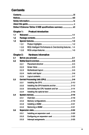
Serial ATA 3.0 Gb/s technology and SATA-On-The-Go This motherboard supports the next-generation hard drives based on the headphones while playing multi-channel network games. IEEE 1394a support The IEEE 1394a ...for details. This capability ensures rapid transfer of data from WAN to PCIe 1.0 devices. See page 2-29 for details. ROG Striker II Extreme / Striker II NSE 1-3 Dual-channel DDR3 1333 memory support The motherboard supports DDR3 memory that simultaneously sends different audio streams to serve as digital television, digital video camcorders, storage peripherals & other ...
Serial ATA 3.0 Gb/s technology and SATA-On-The-Go This motherboard supports the next-generation hard drives based on the headphones while playing multi-channel network games. IEEE 1394a support The IEEE 1394a ...for details. This capability ensures rapid transfer of data from WAN to PCIe 1.0 devices. See page 2-29 for details. ROG Striker II Extreme / Striker II NSE 1-3 Dual-channel DDR3 1333 memory support The motherboard supports DDR3 memory that simultaneously sends different audio streams to serve as digital television, digital video camcorders, storage peripherals & other ...

User Manual
Page 21
... details. Simply reboot the system, and the BIOS automatically restores the CPU default settings for maximum performance achievement. ASUS O.C. ROG Striker II Extreme / Striker II NSE 1-5 The COP EX allows more freedom and less constraint for each parameter. Profile that no need to open...system hangs due to overclocking failure, there is critical but risky. See page 5-33 for overclockers. Profile The motherboard features the ASUS O.C. Let the motherboard do the talking! Acting as the "red zone" of extreme performance, overvoltage adjustment is no one knows when ...
... details. Simply reboot the system, and the BIOS automatically restores the CPU default settings for maximum performance achievement. ASUS O.C. ROG Striker II Extreme / Striker II NSE 1-5 The COP EX allows more freedom and less constraint for each parameter. Profile that no need to open...system hangs due to overclocking failure, there is critical but risky. See page 5-33 for overclockers. Profile The motherboard features the ASUS O.C. Let the motherboard do the talking! Acting as the "red zone" of extreme performance, overvoltage adjustment is no one knows when ...

User Manual
Page 23
...voltage for the entire system. See pages 4-35 and 5-32 for details. See page 4-40 for details. 1.3.4 ASUS special features Fanless Design-Stack Cool 2 ASUS Stack Cool 2 is a fan-less and zero-noise cooling solution that allows you are temporarily away. See page ...boot logos. ASUS MyLogo 3 ASUS MyLogo 3 is utilized, ensuring effective heat dissipation for power saving during light loading. ROG Striker II Extreme / Striker II NSE 1-7 To wake the system and return to dissipate heat these critical components generate. See pages 2-16 and 2-17 for details. The motherboard uses a ...
...voltage for the entire system. See pages 4-35 and 5-32 for details. See page 4-40 for details. 1.3.4 ASUS special features Fanless Design-Stack Cool 2 ASUS Stack Cool 2 is a fan-less and zero-noise cooling solution that allows you are temporarily away. See page ...boot logos. ASUS MyLogo 3 ASUS MyLogo 3 is utilized, ensuring effective heat dissipation for power saving during light loading. ROG Striker II Extreme / Striker II NSE 1-7 To wake the system and return to dissipate heat these critical components generate. See pages 2-16 and 2-17 for details. The motherboard uses a ...
User Manual
Page 26
Chapter summary 2 2.1 Before you proceed 2-1 2.2 Motherboard overview 2-5 2.3 Central Processing Unit (CPU 2-9 2.4 System memory 2-18 2.5 Expansion slots 2-22 2.6 Slide switch 2-26 2.7 Aduio card, EL I/O shield, and LCD Poster Installation.......... 2-27 2.8 Connectors 2-29 ROG Striker II Extreme / Striker II NSE
Chapter summary 2 2.1 Before you proceed 2-1 2.2 Motherboard overview 2-5 2.3 Central Processing Unit (CPU 2-9 2.4 System memory 2-18 2.5 Expansion slots 2-22 2.6 Slide switch 2-26 2.7 Aduio card, EL I/O shield, and LCD Poster Installation.......... 2-27 2.8 Connectors 2-29 ROG Striker II Extreme / Striker II NSE

User Manual
Page 27
... CPU LED and the table below for power status. For more information about voltage adjustment, refer to the motherboard, peripherals, and/or components. Refer to display in BIOS. CPU_CRAZY CPU_HIGH CPU_NORMAL STRIKER II EXTREME STRIKER II EXTREME/ STRIKER II NSE CPU LED CPU Voltage CPU PLL Voltage Normal (green) 1.10000~1.50000 1.50000~1.60000 High (yellow) 1.50625~1.69375 1.62000...
... CPU LED and the table below for power status. For more information about voltage adjustment, refer to the motherboard, peripherals, and/or components. Refer to display in BIOS. CPU_CRAZY CPU_HIGH CPU_NORMAL STRIKER II EXTREME STRIKER II EXTREME/ STRIKER II NSE CPU LED CPU Voltage CPU PLL Voltage Normal (green) 1.10000~1.50000 1.50000~1.60000 High (yellow) 1.50625~1.69375 1.62000...
User Manual
Page 30
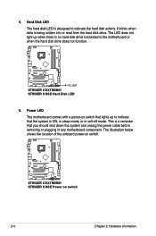
... with a power-on switch that lights up when there is a reminder that the system is designed to the motherboard or when the hard disk drive does not function. 5. This is no hard disk drive connected to indicate the hard disk...in soft‑off mode. It blinks when data is being written into or read from the hard disk drive. STRIKER II EXTREME HD_LED STRIKER II EXTREME/ STRIKER II NSE Hard Disk LED 6. STRIKER II EXTREME STRIKER II EXTREME/ STRIKER II NSE Power on switch. The illustration below shows the location of the onboard power-on switch 2-4 Chapter 2: Hardware information...
... with a power-on switch that lights up when there is a reminder that the system is designed to the motherboard or when the hard disk drive does not function. 5. This is no hard disk drive connected to indicate the hard disk...in soft‑off mode. It blinks when data is being written into or read from the hard disk drive. STRIKER II EXTREME HD_LED STRIKER II EXTREME/ STRIKER II NSE Hard Disk LED 6. STRIKER II EXTREME STRIKER II EXTREME/ STRIKER II NSE Power on switch. The illustration below shows the location of the onboard power-on switch 2-4 Chapter 2: Hardware information...
User Manual
Page 31
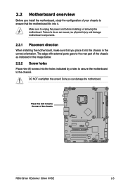
... cause you physical injury and damage motherboard components. 2.2.1 Placement direction When installing the motherboard, make sure that the motherboard fits into it into the holes indicated by circles to secure the motherboard to the chassis. DO NOT overtighten...motherboard, study the configuration of the chassis as indicated in the image below. 2.2.2 Screw holes Place nine (9) screws into the chassis in the correct orientation. Make sure to do so can damage the motherboard. Place this side towards the rear of the chassis STRIKER II EXTREME ROG Striker II Extreme / Striker II NSE...
... cause you physical injury and damage motherboard components. 2.2.1 Placement direction When installing the motherboard, make sure that the motherboard fits into it into the holes indicated by circles to secure the motherboard to the chassis. DO NOT overtighten...motherboard, study the configuration of the chassis as indicated in the image below. 2.2.2 Screw holes Place nine (9) screws into the chassis in the correct orientation. Make sure to do so can damage the motherboard. Place this side towards the rear of the chassis STRIKER II EXTREME ROG Striker II Extreme / Striker II NSE...
User Manual
Page 32
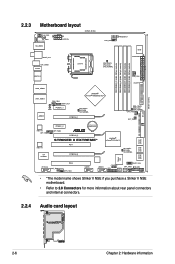
2.2.3 Motherboard layout CHA_FAN1 EL_CON LCD_CON KB_USB56 EATX12V 24.5cm (9.6in) SPDIF_O12 CLR_CMOS E1394 LGA775 CPU_FAN FREQUENCY CPU_CRAZY CPU_HIGH CPU_NORMAL BIOS EATXPWR DDR3 DIMM_A1 (64bit, 240-... SB_NORMAL SATA3 SATA4 SATA5 SATA6 Super I/O IE1394_2 OPT_TEMP3 PCI2 OPT_FAN3 USB78 USB910 CHASSIS ADH CLRTC_SW CHA_FAN3 RESET HD_LED PANEL • *The model name shows Striker II NSE if you purchase a Striker II NSE motherboard. • Refer to 2.8 Connectors for more information about rear panel connectors and internal connectors. 2.2.4 Audio card layout SUPREMEFX...
2.2.3 Motherboard layout CHA_FAN1 EL_CON LCD_CON KB_USB56 EATX12V 24.5cm (9.6in) SPDIF_O12 CLR_CMOS E1394 LGA775 CPU_FAN FREQUENCY CPU_CRAZY CPU_HIGH CPU_NORMAL BIOS EATXPWR DDR3 DIMM_A1 (64bit, 240-... SB_NORMAL SATA3 SATA4 SATA5 SATA6 Super I/O IE1394_2 OPT_TEMP3 PCI2 OPT_FAN3 USB78 USB910 CHASSIS ADH CLRTC_SW CHA_FAN3 RESET HD_LED PANEL • *The model name shows Striker II NSE if you purchase a Striker II NSE motherboard. • Refer to 2.8 Connectors for more information about rear panel connectors and internal connectors. 2.2.4 Audio card layout SUPREMEFX...
User Manual
Page 35
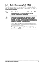
...Striker II Extreme / Striker II NSE 2-9 2.3 Central Processing Unit (CPU) The motherboard comes with the cap on the socket and the socket contacts are unplugged before installing the CPU. • If installing a dual-core CPU, connect the chassis fan cable to the CHA_FAN1 connector to the PnP cap/socket contacts/motherboard.../removal, or misplacement/loss/ incorrect removal of the motherboard, make sure that all power cables are not bent. ASUS will process Return Merchandise Authorization (RMA) requests only if the motherboard comes with a surface mount LGA775 socket designed for ...
...Striker II Extreme / Striker II NSE 2-9 2.3 Central Processing Unit (CPU) The motherboard comes with the cap on the socket and the socket contacts are unplugged before installing the CPU. • If installing a dual-core CPU, connect the chassis fan cable to the CHA_FAN1 connector to the PnP cap/socket contacts/motherboard.../removal, or misplacement/loss/ incorrect removal of the motherboard, make sure that all power cables are not bent. ASUS will process Return Merchandise Authorization (RMA) requests only if the motherboard comes with a surface mount LGA775 socket designed for ...

User Manual
Page 36
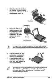
Locate the CPU socket on your thumb (A), then move it is on the motherboard. To prevent damage to the left . 2. Retention tab A Load lever PnP cap B This side of the arrow to a 135º angle. 2-10 Chapter 2: Hardware information 2.3.1 ... a CPU. 3. Lift the load lever in the direction of the socket box should face you and the load lever is released from the retention tab. STRIKER II EXTREME STRIKER II EXTREME/ STRIKER II NSE CPU socket 775 Before installing the CPU, make sure that the cam box is facing towards you .
Locate the CPU socket on your thumb (A), then move it is on the motherboard. To prevent damage to the left . 2. Retention tab A Load lever PnP cap B This side of the arrow to a 135º angle. 2-10 Chapter 2: Hardware information 2.3.1 ... a CPU. 3. Lift the load lever in the direction of the socket box should face you and the load lever is released from the retention tab. STRIKER II EXTREME STRIKER II EXTREME/ STRIKER II NSE CPU socket 775 Before installing the CPU, make sure that the cam box is facing towards you .
User Manual
Page 37
... force the CPU into the socket to remove (B). Close the load plate (A), then A push the load lever (B) until it snaps into the CPU notch. The motherboard supports Intel® LGA775 processors with your thumb and forefinger to a 100º angle (A), then push the PnP cap from the load plate window to... socket alignment key into the retention tab. 7. B A Load plate Alignment key 5. CPU notch Gold triangle mark The CPU fits in only one correct orientation. ROG Striker II Extreme / Striker II NSE 2-11
... force the CPU into the socket to remove (B). Close the load plate (A), then A push the load lever (B) until it snaps into the CPU notch. The motherboard supports Intel® LGA775 processors with your thumb and forefinger to a 100º angle (A), then push the PnP cap from the load plate window to... socket alignment key into the retention tab. 7. B A Load plate Alignment key 5. CPU notch Gold triangle mark The CPU fits in only one correct orientation. ROG Striker II Extreme / Striker II NSE 2-11
User Manual
Page 39
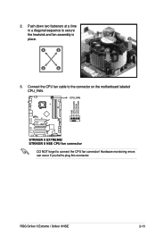
A A A B B B A 3. CPU_FAN GND CPU FAN PWR CPU FAN IN CPU FAN PWM STRIKER II EXTREME STRIKER II EXTREME/ STRIKER II NSE CPU fan connector DO NOT forget to plug this connector. Hardware monitoring errors can occur if you fail to connect the CPU fan connector! Connect the CPU fan cable to secure the heatsink and fan assembly in B place. ROG Striker II Extreme / Striker II NSE 2-13 Push down two fasteners at a time in a diagonal sequence to the connector on the motherboard labeled CPU_FAN. 2.
A A A B B B A 3. CPU_FAN GND CPU FAN PWR CPU FAN IN CPU FAN PWM STRIKER II EXTREME STRIKER II EXTREME/ STRIKER II NSE CPU fan connector DO NOT forget to plug this connector. Hardware monitoring errors can occur if you fail to connect the CPU fan connector! Connect the CPU fan cable to secure the heatsink and fan assembly in B place. ROG Striker II Extreme / Striker II NSE 2-13 Push down two fasteners at a time in a diagonal sequence to the connector on the motherboard labeled CPU_FAN. 2.

User Manual
Page 43
Plug the optional fan cable in the PWR_FAN connector on the motherboard. ROG Striker II Extreme / Striker II NSE 2-17 The photo shows that two fans are installed to install the other optional fan. 6. 5. Follow Step 1 to 4 to the motherboard.
Plug the optional fan cable in the PWR_FAN connector on the motherboard. ROG Striker II Extreme / Striker II NSE 2-17 The photo shows that two fans are installed to install the other optional fan. 6. 5. Follow Step 1 to 4 to the motherboard.

User Manual
Page 44
... but is notched differently. DDR3 modules are developed for details. 2.4 System memory 2.4.1 Overview The motherboard comes with less power consumption. The figure illustrates the location of the DDR3 DIMM sockets: STRIKER II EXTREME DIMM_A1 DIMM_A2 DIMM_B1 DIMM_B2 STRIKER II EXTREME/ STRIKER II NSE 240-pin DDR3 DIMM sockets Channel Channel A Channel B Sockets DIMM_A1 and DIMM_A2 DIMM_B1 and DIMM_B2...
... but is notched differently. DDR3 modules are developed for details. 2.4 System memory 2.4.1 Overview The motherboard comes with less power consumption. The figure illustrates the location of the DDR3 DIMM sockets: STRIKER II EXTREME DIMM_A1 DIMM_A2 DIMM_B1 DIMM_B2 STRIKER II EXTREME/ STRIKER II NSE 240-pin DDR3 DIMM sockets Channel Channel A Channel B Sockets DIMM_A1 and DIMM_A2 DIMM_B1 and DIMM_B2...
User Manual
Page 45
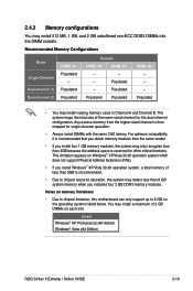
... in Channel A and Channel B. Populated Populated Populated DIMM_B2 - - - Populated Populated Sockets DIMM_A2 DIMM_B1 - - - Populated - Notes on memory limitations • Due to chipset limitation, this motherboard can only support up to chipset resource allocation, the system may install a maximum of the lower-sized channel for other critical functions. Recommended Memory Configurations...address space is recommended. • Due to 8 GB on each slot. 64-bit Windows® XP Professional x64 Edition Windows® Vista x64 Edition ROG Striker II Extreme / Striker II NSE 2-19
... in Channel A and Channel B. Populated Populated Populated DIMM_B2 - - - Populated Populated Sockets DIMM_A2 DIMM_B1 - - - Populated - Notes on memory limitations • Due to chipset limitation, this motherboard can only support up to chipset resource allocation, the system may install a maximum of the lower-sized channel for other critical functions. Recommended Memory Configurations...address space is recommended. • Due to 8 GB on each slot. 64-bit Windows® XP Professional x64 Edition Windows® Vista x64 Edition ROG Striker II Extreme / Striker II NSE 2-19
User Manual
Page 46
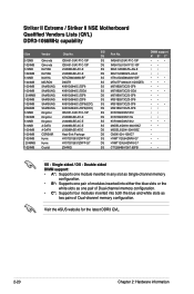
... Supports four modules inserted into both the blue and white slots as two pairs of Dual-channel memory configuration. Visit the ASUS website for the latest DDR3 QVL. 2-20 Chapter 2: Hardware information SS IMSH51U03A1F1C-10F DS IMSH1GU13A1F1C-10F SS EBJ51UD8BAFA-AG-E...1066C7 SS HYMT112U64ZNF8-G7 DS HYMT125U64ZNF8-G7 SS CT12864BA1067.8SFB DIMM support A* B* C SS - Single-sided / DS - Striker II Extreme / Striker II NSE Motherboard Qualified Vendors Lists (QVL) DDR3-1066MHz capability Size 512MB 1024MB 512MB 1024MB 512MB 1024MB 1024MB 1024MB 2048MB 1024MB 1024MB 2048MB ...
... Supports four modules inserted into both the blue and white slots as two pairs of Dual-channel memory configuration. Visit the ASUS website for the latest DDR3 QVL. 2-20 Chapter 2: Hardware information SS IMSH51U03A1F1C-10F DS IMSH1GU13A1F1C-10F SS EBJ51UD8BAFA-AG-E...1066C7 SS HYMT112U64ZNF8-G7 DS HYMT125U64ZNF8-G7 SS CT12864BA1067.8SFB DIMM support A* B* C SS - Single-sided / DS - Striker II Extreme / Striker II NSE Motherboard Qualified Vendors Lists (QVL) DDR3-1066MHz capability Size 512MB 1024MB 512MB 1024MB 512MB 1024MB 1024MB 1024MB 2048MB 1024MB 1024MB 2048MB ...

User Manual
Page 47
... the DIMM into a socket to avoid damaging the DIMM. • The DDR3 DIMM sockets do so can cause severe damage to both the motherboard and the components. ROG Striker II Extreme / Striker II NSE 2-21 The DIMM might get damaged when it fits in place and the DIMM is properly seated. 3 2 DDR3 DIMM notch 1 Unlocked retaining...
... the DIMM into a socket to avoid damaging the DIMM. • The DDR3 DIMM sockets do so can cause severe damage to both the motherboard and the components. ROG Striker II Extreme / Striker II NSE 2-21 The DIMM might get damaged when it fits in place and the DIMM is properly seated. 3 2 DDR3 DIMM notch 1 Unlocked retaining...


