
User Manual
Page 8
...& faster), AMD-K5™ (PR75-PR133), AMD-K6™ (PR166 & faster). • Versatile Memory Support: Equipped with four SIMM sockets to support 4- 64MB 72-pin Fast Page Mode (FPM) or Extended Data Out (EDO) memory modules up to communicate within a standard protocol...• Level 2 Cache: Comes with EPP and ECP capabilities. • Desktop Management Interface (DMI): Supports DMI through onboard firmware. 8 ASUS SP97 / SP97-V User's Manual FEATURES (ASUS SP97) II. Supports Japanese "Floppy 3 mode" (3.5-inch disk drive: 1.2MB) and LS-120 floppy disk drives (3.5-inch disk drive: 120...
...& faster), AMD-K5™ (PR75-PR133), AMD-K6™ (PR166 & faster). • Versatile Memory Support: Equipped with four SIMM sockets to support 4- 64MB 72-pin Fast Page Mode (FPM) or Extended Data Out (EDO) memory modules up to communicate within a standard protocol...• Level 2 Cache: Comes with EPP and ECP capabilities. • Desktop Management Interface (DMI): Supports DMI through onboard firmware. 8 ASUS SP97 / SP97-V User's Manual FEATURES (ASUS SP97) II. Supports Japanese "Floppy 3 mode" (3.5-inch disk drive: 1.2MB) and LS-120 floppy disk drives (3.5-inch disk drive: 120...

User Manual
Page 11
ATX Power Conn. FEATURES The ASUS SP97 Motherboard 3 PCI Slots 2 ISA Slots 1 ISA/PCI Shared Slot AT Power Conn. Floppy Connector IDE Connectors USB, PS/2 Mouse, Infrared Super Multi I/O Parallel Serial Keyboard 4 SIMM Sockets SiS5582 or 5598 (VGA) Chipset Programmable Flash ROM CPU ZIF Socket 7 Switching Voltage Regulators 512KB/256KB Pipelined Burst L2 Cache ASUS SP97 / SP97-V User's Manual 11 FEATURES (ASUS SP97) II. II.
ATX Power Conn. FEATURES The ASUS SP97 Motherboard 3 PCI Slots 2 ISA Slots 1 ISA/PCI Shared Slot AT Power Conn. Floppy Connector IDE Connectors USB, PS/2 Mouse, Infrared Super Multi I/O Parallel Serial Keyboard 4 SIMM Sockets SiS5582 or 5598 (VGA) Chipset Programmable Flash ROM CPU ZIF Socket 7 Switching Voltage Regulators 512KB/256KB Pipelined Burst L2 Cache ASUS SP97 / SP97-V User's Manual 11 FEATURES (ASUS SP97) II. II.

User Manual
Page 12
INSTALLATION (Motherboard Layout) III. Ratio CPU ZIF Socket 7 Row 0 1 0 1 2 3 2 3 Clock Freq. Panel Connectors 12 ASUS SP97 / SP97-V User's Manual FS3 Clock Freq FS0 FS1 FS2 NOTE: Outlined components are available only on motherboards with onboard VGA. III. INSTALLATION ASUS SP97 Motherboard Layout PCI Slot 3 PCI Slot 4 ISA Slot 1 Feature...P9 AT Power Input ATX Power Input VGA Select VGA Select 1 SIMM Socket 4 (32-bit, 72-pin module) SIMM Socket 3 (32-bit, 72-pin module) SIMM Socket 2 (32-bit, 72-pin module) SIMM Socket 1 (32-bit, 72-pin module) R 512KB/256KB Pipelined Burst ...
INSTALLATION (Motherboard Layout) III. Ratio CPU ZIF Socket 7 Row 0 1 0 1 2 3 2 3 Clock Freq. Panel Connectors 12 ASUS SP97 / SP97-V User's Manual FS3 Clock Freq FS0 FS1 FS2 NOTE: Outlined components are available only on motherboards with onboard VGA. III. INSTALLATION ASUS SP97 Motherboard Layout PCI Slot 3 PCI Slot 4 ISA Slot 1 Feature...P9 AT Power Input ATX Power Input VGA Select VGA Select 1 SIMM Socket 4 (32-bit, 72-pin module) SIMM Socket 3 (32-bit, 72-pin module) SIMM Socket 2 (32-bit, 72-pin module) SIMM Socket 1 (32-bit, 72-pin module) R 512KB/256KB Pipelined Burst ...

User Manual
Page 13
... Setting p. 18 Onboard VGA Interrupt Selection Expansion Slots 1) System Memory p. 20 System Memory (SIMM) 2) SIMM1,SIMM2,SIMM3,SIMM4 p. 21 72-Pin SIMM Sockets 3) CPU p. 23 Central Processing Unit (CPU) Socket 4) PCI1, PCI2, PCI3, PCI4 p. 24 32-bit PCI Bus Expansion Slots 5) SLOT1, SLOT2, SLOT3 p. 24 16-bit ISA Bus Expansion Slots Connectors...) 18) IDELED p. 32 IDE Activity LED (2 pins) 19) VGACON (optional) p. 32 VGA Connector (16-pin block) 20) FEATURE p. 33 Video Feature Connector (28-pin block) ASUS SP97 / SP97-V User's Manual 13
... Setting p. 18 Onboard VGA Interrupt Selection Expansion Slots 1) System Memory p. 20 System Memory (SIMM) 2) SIMM1,SIMM2,SIMM3,SIMM4 p. 21 72-Pin SIMM Sockets 3) CPU p. 23 Central Processing Unit (CPU) Socket 4) PCI1, PCI2, PCI3, PCI4 p. 24 32-bit PCI Bus Expansion Slots 5) SLOT1, SLOT2, SLOT3 p. 24 16-bit ISA Bus Expansion Slots Connectors...) 18) IDELED p. 32 IDE Activity LED (2 pins) 19) VGACON (optional) p. 32 VGA Connector (16-pin block) 20) FEATURE p. 33 Video Feature Connector (28-pin block) ASUS SP97 / SP97-V User's Manual 13

User Manual
Page 20
... Configuration" in pairs so that each Row (refer to 256MB. INSTALLATION (System Memory) 20 ASUS SP97 / SP97-V User's Manual Memory Socket SIMM Sockets 1&2 (Rows 0 & 1) SIMM Sockets 3&4 (Rows 2 & 3) SIMM Memory Module 4MB, 8MB, 16MB, 32MB, 64MB 72-pin FPM or EDO SIMM (DIMM Sockets must be empty) 4MB, 8MB, 16MB, 32MB, 64MB 72-pin FPM or EDO SIMM...
... Configuration" in pairs so that each Row (refer to 256MB. INSTALLATION (System Memory) 20 ASUS SP97 / SP97-V User's Manual Memory Socket SIMM Sockets 1&2 (Rows 0 & 1) SIMM Sockets 3&4 (Rows 2 & 3) SIMM Memory Module 4MB, 8MB, 16MB, 32MB, 64MB 72-pin FPM or EDO SIMM (DIMM Sockets must be empty) 4MB, 8MB, 16MB, 32MB, 64MB 72-pin FPM or EDO SIMM...

User Manual
Page 21
... Clip 72 Pin DRAM in only one orientation as shown because the plastic safety tab on one end of the SIMM sockets requires the notched end of the clips ASUS SP97 / SP97-V User's Manual 21 III. INSTALLATION SIMM Installation 1. The plastic guides should go through the two mounting holes and the...45-degree angle, making sure that it clicks into a vertical position so that all the contacts are aligned with the socket. 3. The SIMM memory modules will fit in SIMM Socket Safety Tab (This Side Only) Mounting Hole To release the memory module, push both clips outward and rock the ...
... Clip 72 Pin DRAM in only one orientation as shown because the plastic safety tab on one end of the SIMM sockets requires the notched end of the clips ASUS SP97 / SP97-V User's Manual 21 III. INSTALLATION SIMM Installation 1. The plastic guides should go through the two mounting holes and the...45-degree angle, making sure that it clicks into a vertical position so that all the contacts are aligned with the socket. 3. The SIMM memory modules will fit in SIMM Socket Safety Tab (This Side Only) Mounting Hole To release the memory module, push both clips outward and rock the ...

User Manual
Page 23
...BUS Frequency Selection depending on the processor that came with Pentium Processor ASUS SP97 / SP97-V User's Manual 23 Notice that corner of the square array of the lever. Central Processing Unit (CPU) The motherboard provides a 321-pin ZIF Socket 7 that corner. Insert the CPU with the correct orientation as ...picture is backward compatible with the white dot as shown. III. Because the CPU has a corner pin for three of the CPU with ZIF Socket 5 processors. INSTALLATION (CPU) III. Once the processor is not the case, then install a fan before you will only fit in only ...
...BUS Frequency Selection depending on the processor that came with Pentium Processor ASUS SP97 / SP97-V User's Manual 23 Notice that corner of the square array of the lever. Central Processing Unit (CPU) The motherboard provides a 321-pin ZIF Socket 7 that corner. Insert the CPU with the correct orientation as ...picture is backward compatible with the white dot as shown. III. Because the CPU has a corner pin for three of the CPU with ZIF Socket 5 processors. INSTALLATION (CPU) III. Once the processor is not the case, then install a fan before you will only fit in only ...

User Manual
Page 50
... for each field is determined for each PCI slot. BIOS (PnP and PCI) NOTE: SETUP Defaults are noted in parenthesis next to this motherboard. 50 ASUS SP97 / SP97-V User's Manual Slot 1 (Right) is selected. The other options are installed, interrupts may be set how IRQ use INTA#, thus all installed PCI ...cards must be reassigned by the OS when Yes is nearest the memory sockets. All PCI bus slots on the screen set to each slot. PCI Latency Timer (32 PCI Clock) The default setting of NA, 5, 7, 9, 10, 11...
... for each field is determined for each PCI slot. BIOS (PnP and PCI) NOTE: SETUP Defaults are noted in parenthesis next to this motherboard. 50 ASUS SP97 / SP97-V User's Manual Slot 1 (Right) is selected. The other options are installed, interrupts may be set how IRQ use INTA#, thus all installed PCI ...cards must be reassigned by the OS when Yes is nearest the memory sockets. All PCI bus slots on the screen set to each slot. PCI Latency Timer (32 PCI Clock) The default setting of NA, 5, 7, 9, 10, 11...
User Manual
Page 63
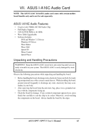
... Card NOTE: The ASUS I -A16C (Features / Precautions) VII. ASUS SP97 / SP97-V User's Manual 63 VII. Keep the ASUS I-A16C stored in its socket. Observe the following precautions while unpacking and handling the board: • Before handling the board, discharge static electricity from ...facing up. • Check the board for sale separately. ASUS I -A16C is not for damage. If any socketed component appears loose, press firmly but carefully to discharge any static electricity that may accumulate in your system. The ASUS I -A16C Audio Features • Creative Labs ViBRA 16C PnP...
... Card NOTE: The ASUS I -A16C (Features / Precautions) VII. ASUS SP97 / SP97-V User's Manual 63 VII. Keep the ASUS I-A16C stored in its socket. Observe the following precautions while unpacking and handling the board: • Before handling the board, discharge static electricity from ...facing up. • Check the board for sale separately. ASUS I -A16C is not for damage. If any socketed component appears loose, press firmly but carefully to discharge any static electricity that may accumulate in your system. The ASUS I -A16C Audio Features • Creative Labs ViBRA 16C PnP...


