
User Manual
Page 12
Rampage Extreme specifications summary CPU Chipset System Bus Memory Expansion Slots CrossFireX™ Technology Storage LAN LGA775 socket for Intel® Core™2 Extreme / Core™2 Quad /...SIL5723 controller (SPEEDING HDD Technology): - 2 x SATA 3.0 Gb/s ports - Supports up to www.asus.com for Intel CPU support list Intel® X48 / ICH9R with the ��a�u�d&#...65533;6�s��p�e�e�d��) 3 x PCIe x1 (PCIEX1_1 (black) is compatible with Intel® Fast Memory Access Technology 1600/1333/1066/800 MHz Dual...
Rampage Extreme specifications summary CPU Chipset System Bus Memory Expansion Slots CrossFireX™ Technology Storage LAN LGA775 socket for Intel® Core™2 Extreme / Core™2 Quad /...SIL5723 controller (SPEEDING HDD Technology): - 2 x SATA 3.0 Gb/s ports - Supports up to www.asus.com for Intel CPU support list Intel® X48 / ICH9R with the ��a�u�d&#...65533;6�s��p�e�e�d��) 3 x PCIe x1 (PCIEX1_1 (black) is compatible with Intel® Fast Memory Access Technology 1600/1333/1066/800 MHz Dual...

User Manual
Page 14
Rampage Extreme specifications summary Back Panel I/O Ports Internal I/O Connectors BIOS Features Manageability Accessories 1 x PS/2 Keyboard port 1 x eSATA port 1 x IEEE1394a port 2 x LAN (RJ45) ports 6 x USB 2.0/1.1 ports 1 x Clr CMOS switch 3 x USB connectors support additional 6 USB ports 1 x Floppy disk drive connector 1 x IDE connector for two devices 6 x SATA connectors (Blue) 2 x Speeding HDD connectors (Black... Kit for NB and MOS SupremeFX X-Fi Audio Card LCD Poster ASUS Optional Fan DIY Pedestal 3 in 1 ASUS Q-connector kit UltraDMA 133/100/66 cable Floppy disk drive cable Serial...
Rampage Extreme specifications summary Back Panel I/O Ports Internal I/O Connectors BIOS Features Manageability Accessories 1 x PS/2 Keyboard port 1 x eSATA port 1 x IEEE1394a port 2 x LAN (RJ45) ports 6 x USB 2.0/1.1 ports 1 x Clr CMOS switch 3 x USB connectors support additional 6 USB ports 1 x Floppy disk drive connector 1 x IDE connector for two devices 6 x SATA connectors (Blue) 2 x Speeding HDD connectors (Black... Kit for NB and MOS SupremeFX X-Fi Audio Card LCD Poster ASUS Optional Fan DIY Pedestal 3 in 1 ASUS Q-connector kit UltraDMA 133/100/66 cable Floppy disk drive cable Serial...

User Manual
Page 35
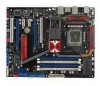
...FLOPPY) 6. Clear RTC RAM (3-pin CLRTC_SW) 10. Power-on switch 14. Chassis intrusion connector (4-1 pin CHASSIS) 19. ATX power connectors (24-pin EATXPWR, 8-pin ATX12V) 3. System panel connector (20-8 pin PANEL) 11. USB connectors (10... ATA connectors (7-pin SPEEDING HDD1/2 [black]) 9. DDR3 DIMM slots 5. 2.2.3 Layout contents Connectors/Jumpers/Switches/Slots 1. USB910; IDE connector (40-1 pin PRI_EIDE) 7. Thermal sensor cable connectors (2-pin OPT_TEMP1-3) 18. LGA775 CPU Socket 4. TOGGLE, CONFIRM, SELECT switches 16. ROG Rampage Extreme 2-5
...FLOPPY) 6. Clear RTC RAM (3-pin CLRTC_SW) 10. Power-on switch 14. Chassis intrusion connector (4-1 pin CHASSIS) 19. ATX power connectors (24-pin EATXPWR, 8-pin ATX12V) 3. System panel connector (20-8 pin PANEL) 11. USB connectors (10... ATA connectors (7-pin SPEEDING HDD1/2 [black]) 9. DDR3 DIMM slots 5. 2.2.3 Layout contents Connectors/Jumpers/Switches/Slots 1. USB910; IDE connector (40-1 pin PRI_EIDE) 7. Thermal sensor cable connectors (2-pin OPT_TEMP1-3) 18. LGA775 CPU Socket 4. TOGGLE, CONFIRM, SELECT switches 16. ROG Rampage Extreme 2-5

User Manual
Page 49
...slots. See page 2-32 for better thermal environment. ROG Rampage Extreme 2-19 See page 2-29 for the location of the slots. 2.5.5 PCI Express x1 slots This motherboard supports PCI Express x1 network cards, SCSI cards and other compatible cards to the black PCIe x1 slot. • Install a PCIe x1 ...device to a PCIe x1 slot prior to the figure below for the connector location. Refer to the motherboard connector labeled OPT_FAN1/2/3 for details. • Install two ATI ...
...slots. See page 2-32 for better thermal environment. ROG Rampage Extreme 2-19 See page 2-29 for the location of the slots. 2.5.5 PCI Express x1 slots This motherboard supports PCI Express x1 network cards, SCSI cards and other compatible cards to the black PCIe x1 slot. • Install a PCIe x1 ...device to a PCIe x1 slot prior to the figure below for the connector location. Refer to the motherboard connector labeled OPT_FAN1/2/3 for details. • Install two ATI ...

User Manual
Page 53
... insert a SATA connector into this port becomes Front Speaker Out. 7. USB 2.0 ports 5 and 6. ROG Rampage Extreme 2-23 These 4-pin Universal Serial Bus (USB) ports are available for connecting USB 2.0 devices. Center/Subwoofer port (orange). Rear Speaker Out port (black). This port connects the side speakers in 2, 4, 6, or 8-channel configuration. USB 2.0 ports 1 and 2. 5. This...
... insert a SATA connector into this port becomes Front Speaker Out. 7. USB 2.0 ports 5 and 6. ROG Rampage Extreme 2-23 These 4-pin Universal Serial Bus (USB) ports are available for connecting USB 2.0 devices. Center/Subwoofer port (orange). Rear Speaker Out port (black). This port connects the side speakers in 2, 4, 6, or 8-channel configuration. USB 2.0 ports 1 and 2. 5. This...

User Manual
Page 55
Connect the blue connector to the motherboard's IDE connector, then select one of device(s) Master Slave Master Slave Cable connector Black Black Gray Black or gray • Pin 20 on the IDE connector is for Ultra DMA 133/100/66 IDE devices. Single device Two devices Drive ...Cable-Select Master Slave Mode of the following modes to match the covered hole on each Ultra DMA 133/100/66 signal cable: blue, black, and gray. ROG Rampage Extreme 2-25 IDE connector (40-1 pin PRI_EIDE) The onboard IDE connector is removed to configure your device. If any device jumper is set...
Connect the blue connector to the motherboard's IDE connector, then select one of device(s) Master Slave Master Slave Cable connector Black Black Gray Black or gray • Pin 20 on the IDE connector is for Ultra DMA 133/100/66 IDE devices. Single device Two devices Drive ...Cable-Select Master Slave Mode of the following modes to match the covered hole on each Ultra DMA 133/100/66 signal cable: blue, black, and gray. ROG Rampage Extreme 2-25 IDE connector (40-1 pin PRI_EIDE) The onboard IDE connector is removed to configure your device. If any device jumper is set...

User Manual
Page 57
... devices or hotplug function. • Back up your data stored in the two SATA hard drives before using Speeding HDD function. ROG Rampage Extreme 2-27 4. To install SATA hard disk drives: 1. In Super Speed mode, data stored in the drive connected to SPEEDING HDD2 port...configuration with the Speeding HDD Technology through the onboard Silicon Image® SIL5723 controller. SIL5723 Serial ATA RAID connectors (7-pin SPEEDING HDD1/2 [black]) These connectors are for the Serial ATA signal cables for more information. Prepare two SATA hard disk drives. 2. ��C�...
... devices or hotplug function. • Back up your data stored in the two SATA hard drives before using Speeding HDD function. ROG Rampage Extreme 2-27 4. To install SATA hard disk drives: 1. In Super Speed mode, data stored in the drive connected to SPEEDING HDD2 port...configuration with the Speeding HDD Technology through the onboard Silicon Image® SIL5723 controller. SIL5723 Serial ATA RAID connectors (7-pin SPEEDING HDD1/2 [black]) These connectors are for the Serial ATA signal cables for more information. Prepare two SATA hard disk drives. 2. ��C�...

User Manual
Page 59
... inside the system may damage the motherboard components. ROG Rampage Extreme 2-29 Connect the fan cables to the fan connectors on the fan connectors! • Only the CPU_FAN, CHA_FAN1-3, and OPT_FAN1-3 connectors support the ASUS Fan Xpert feature. • If you install two VGA cards, we recommend that the black wire of each cable matches...
... inside the system may damage the motherboard components. ROG Rampage Extreme 2-29 Connect the fan cables to the fan connectors on the fan connectors! • Only the CPU_FAN, CHA_FAN1-3, and OPT_FAN1-3 connectors support the ASUS Fan Xpert feature. • If you install two VGA cards, we recommend that the black wire of each cable matches...


