
User Guide
Page 14
... your system package for details. You may have to Chapter 7 for the following items. Model Name Chassis Motherboard Component Accessories Optional Items RS920A-E6/RS8 RS924A-E6/RS8 ASUS R21B 2U Rackmount Chassis ASUS KGPX-Q32 Series Server Board 1 x 1620W Redundant Power Supply 1 x SATA Backplane with 8 x SATA Cables 2 x PCIe riser card 1 x Front I/O Shield (FPB-AR14) 1 x Power Supply...
... your system package for details. You may have to Chapter 7 for the following items. Model Name Chassis Motherboard Component Accessories Optional Items RS920A-E6/RS8 RS924A-E6/RS8 ASUS R21B 2U Rackmount Chassis ASUS KGPX-Q32 Series Server Board 1 x 1620W Redundant Power Supply 1 x SATA Backplane with 8 x SATA Cables 2 x PCIe riser card 1 x Front I/O Shield (FPB-AR14) 1 x Power Supply...

User Guide
Page 15
1.2 Serial number label Before requesting support from the ASUS Technical Support team, you must take note of the product, ASUS Technical Support team members can then offer a quicker and satisfying solution to your problems. RS924A -E6/RS8 xxS0xxxxxxxxxx ASUS RS920A-E6/RS8; With the correct serial number of the product's serial number containing 14 characters such as xxS0xxxxxxxxxx. See the figure below. RS924A-E6/RS8 1-3
1.2 Serial number label Before requesting support from the ASUS Technical Support team, you must take note of the product, ASUS Technical Support team members can then offer a quicker and satisfying solution to your problems. RS924A -E6/RS8 xxS0xxxxxxxxxx ASUS RS920A-E6/RS8; With the correct serial number of the product's serial number containing 14 characters such as xxS0xxxxxxxxxx. See the figure below. RS924A-E6/RS8 1-3

User Guide
Page 16
... card (continued on the next page) 1-4 Chapter 1: Product introduction Supports software RAID 0, 1, 5 & 10 Optional: PIKE riser is necessary. Model Name RS920A-E6/RS8 4 x Socket LGA1944 RS924A-E6/RS8 Processor / System Bus Core Logic ASUS Features Fan Speed Control ASWM Enterprise Total Slots Capacity Memory Memory Type Memory Size Total PCI/PCI-X/ PCI-E Slots Expansion Slots Slot...
... card (continued on the next page) 1-4 Chapter 1: Product introduction Supports software RAID 0, 1, 5 & 10 Optional: PIKE riser is necessary. Model Name RS920A-E6/RS8 4 x Socket LGA1944 RS924A-E6/RS8 Processor / System Bus Core Logic ASUS Features Fan Speed Control ASWM Enterprise Total Slots Capacity Memory Memory Type Memory Size Total PCI/PCI-X/ PCI-E Slots Expansion Slots Slot...

User Guide
Page 17
RS924A-E6/RS8 1-5 HDD Bays I = Internal A or S will be hot-swappable Networking LAN Graphic VGA Auxiliary Storage Device Bay (Floppy / Optical Device) Onboard I/O OS Support Anti-virus Software ...: 10°C-35°C / Non operation temperature: -40°C-70°C Non operation humidity:20%-90% ( Non-condensing) *Specifications are subject to change without notice. ASUS RS920A-E6/RS8;
RS924A-E6/RS8 1-5 HDD Bays I = Internal A or S will be hot-swappable Networking LAN Graphic VGA Auxiliary Storage Device Bay (Floppy / Optical Device) Onboard I/O OS Support Anti-virus Software ...: 10°C-35°C / Non operation temperature: -40°C-70°C Non operation humidity:20%-90% ( Non-condensing) *Specifications are subject to change without notice. ASUS RS920A-E6/RS8;

User Guide
Page 18
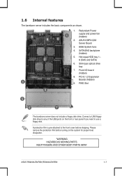
Refer to section 1.7.1 Front panel LEDs for ASUS ASMB5-iKVM controller card only. 1-6 Chapter 1: Product introduction ODD dummy cover Reset button Message LED LAN1/3 LED LAN2/4 LED HDD Access LED USB ports Location ... 1 Power cord connector Redundant power supply LAN port 2 LAN port 3 LAN port 4 PS/2 ports Serial port LAN port 5* VGA port USB ports InfiniBand port (For RS924A-E6/RS8 only) • The rear I /O shield with easily accessible features. 1.4 Front panel features The barebone server displays a simple yet stylish front panel with openings for the...
Refer to section 1.7.1 Front panel LEDs for ASUS ASMB5-iKVM controller card only. 1-6 Chapter 1: Product introduction ODD dummy cover Reset button Message LED LAN1/3 LED LAN2/4 LED HDD Access LED USB ports Location ... 1 Power cord connector Redundant power supply LAN port 2 LAN port 3 LAN port 4 PS/2 ports Serial port LAN port 5* VGA port USB ports InfiniBand port (For RS924A-E6/RS8 only) • The rear I /O shield with easily accessible features. 1.4 Front panel features The barebone server displays a simple yet stylish front panel with openings for the...
User Guide
Page 19
SATA/SAS backplane (hidden) 2 5. PIKE Slot 4 5 6 7 The barebone server does not include a floppy disk drive. RS924A-E6/RS8 1-7 Hot-swap HDD tray 1- 8 (SAS and SATA) 6. Connect a USB floppy disk drive to any of the USB ports on the front or rear ... need to the front cover before turning on the system for proper heat dissipation. *WARNING HAZARDOUS MOVING PARTS KEEP FINGERS AND OTHER BODY PARTS AWAY ASUS RS920A-E6/RS8; Slim-type optical drive bay 7. PCI-E 1,2 Expansion Boards (hidden) 9. A protection film is pre-attached to use a floppy disk. Please remove the ...
SATA/SAS backplane (hidden) 2 5. PIKE Slot 4 5 6 7 The barebone server does not include a floppy disk drive. RS924A-E6/RS8 1-7 Hot-swap HDD tray 1- 8 (SAS and SATA) 6. Connect a USB floppy disk drive to any of the USB ports on the front or rear ... need to the front cover before turning on the system for proper heat dissipation. *WARNING HAZARDOUS MOVING PARTS KEEP FINGERS AND OTHER BODY PARTS AWAY ASUS RS920A-E6/RS8; Slim-type optical drive bay 7. PCI-E 1,2 Expansion Boards (hidden) 9. A protection film is pre-attached to use a floppy disk. Please remove the ...

User Guide
Page 21
1.7.2 LAN (RJ-45) LEDs LAN5 LEDs ACT/LINK LED Status Description OFF No link GREEN Linked ACT/LINK LED SPEED LED SPEED LED Status Description OFF 10 Mbps connection ORANGE 100 Mbps connection LAN1 to LAN4 LEDs ACT/LINK LED Status Description OFF No link GREEN Linked BLINKING Data activity ACT/LINK LED SPEED LED SPEED LED Status Description OFF 10 Mbps connection ORANGE 100 Mbps connection GREEN 1 Gbps connection ASUS RS920A-E6/RS8; RS924A-E6/RS8 1-9
1.7.2 LAN (RJ-45) LEDs LAN5 LEDs ACT/LINK LED Status Description OFF No link GREEN Linked ACT/LINK LED SPEED LED SPEED LED Status Description OFF 10 Mbps connection ORANGE 100 Mbps connection LAN1 to LAN4 LEDs ACT/LINK LED Status Description OFF No link GREEN Linked BLINKING Data activity ACT/LINK LED SPEED LED SPEED LED Status Description OFF 10 Mbps connection ORANGE 100 Mbps connection GREEN 1 Gbps connection ASUS RS920A-E6/RS8; RS924A-E6/RS8 1-9

User Guide
Page 25
ASUS will process Return Merchandise Authorization (RMA) requests only if the motherboard comes with installation instructions for 8/12/16 ...the PnP cap is on your retailer immediately if the PnP cap is shipment/transit-related. • Keep the cap after installing the motherboard. RS924A-E6/RS8 2-3 ASUS will shoulder the cost of the PnP cap. 2.2.1 Installing Socket 1944 CPU To install a CPU: 1. 2.2 Central Processing Unit (CPU) ... is on the socket and the socket contacts are not bent. Locate the CPU socket on the motherboard. ASUS RS920A-E6/RS8; Contact your left.
ASUS will process Return Merchandise Authorization (RMA) requests only if the motherboard comes with installation instructions for 8/12/16 ...the PnP cap is on your retailer immediately if the PnP cap is shipment/transit-related. • Keep the cap after installing the motherboard. RS924A-E6/RS8 2-3 ASUS will shoulder the cost of the PnP cap. 2.2.1 Installing Socket 1944 CPU To install a CPU: 1. 2.2 Central Processing Unit (CPU) ... is on the socket and the socket contacts are not bent. Locate the CPU socket on the motherboard. ASUS RS920A-E6/RS8; Contact your left.

User Guide
Page 27
RS924A-E6/RS8 2-5 If so, skip this step. Close the load plate (F), then push the load lever (G) until it is spread in contact with pre-applied Thermal Interface Material. ASUS RS920A-E6/RS8; G CPU Installation Sequence: CPU1 Configuration CPU1 Socket CPU2 Socket One Processor V Dual Processors V V Quad Processors V V CPU3 Socket CPU3 Socket V V Apply some Thermal Interface Material to the exposed area of the CPU that it snaps into F the retention tab. 7. Some heatsinks come with , ensuring that the heatsink will be in an even thin layer.
RS924A-E6/RS8 2-5 If so, skip this step. Close the load plate (F), then push the load lever (G) until it is spread in contact with pre-applied Thermal Interface Material. ASUS RS920A-E6/RS8; G CPU Installation Sequence: CPU1 Configuration CPU1 Socket CPU2 Socket One Processor V Dual Processors V V Quad Processors V V CPU3 Socket CPU3 Socket V V Apply some Thermal Interface Material to the exposed area of the CPU that it snaps into F the retention tab. 7. Some heatsinks come with , ensuring that the heatsink will be in an even thin layer.
User Guide
Page 29
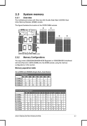
... 1GB/2GB/4GB/8GB/16GB Registerd or 1GB/2GB/4GB Unbuffered with thirty-two (32) Double Data Rate 3 (DDR3) Dual Inline Memory Modules (DIMM) sockets. RS924A-E6/RS8 2-7 Memory population table For UDIMM and RDIMM (Single Rank, Dual Ranks) CPU1 Configuration A2 A1 B2 B1 C2 C1 D2 D1 2 DIMMs V V 4 DIMMs V V V V 6 DIMMs V... F1 G2 G1 H2 H1 2 DIMMs V V 4 DIMMs V V V V 6 DIMMs V V V V V V 8 DIMMs V V V V V V V V 10 DIMMs V V V V V VVV V V 12 DIMMs V V V VVV VVV VVV 14 DIMMs V V V V V V V VVVVV V V 16 DIMMs V V V V V V V V V V V V V V V V ASUS RS920A-E6/RS8;
... 1GB/2GB/4GB/8GB/16GB Registerd or 1GB/2GB/4GB Unbuffered with thirty-two (32) Double Data Rate 3 (DDR3) Dual Inline Memory Modules (DIMM) sockets. RS924A-E6/RS8 2-7 Memory population table For UDIMM and RDIMM (Single Rank, Dual Ranks) CPU1 Configuration A2 A1 B2 B1 C2 C1 D2 D1 2 DIMMs V V 4 DIMMs V V V V 6 DIMMs V... F1 G2 G1 H2 H1 2 DIMMs V V 4 DIMMs V V V V 6 DIMMs V V V V V V 8 DIMMs V V V V V V V V 10 DIMMs V V V V V VVV V V 12 DIMMs V V V VVV VVV VVV 14 DIMMs V V V V V V V VVVVV V V 16 DIMMs V V V V V V V V V V V V V V V V ASUS RS920A-E6/RS8;

User Guide
Page 31
... DIMM on the socket such that it flips out with extra force. Press the retaining clip outward to avoid damaging the DIMM. 3. ASUS RS920A-E6/RS8; Unlock a DIMM socket by both ends of the DIMM simultaneously until the retaining clip snaps back into place, and the DIMM cannot ...the motherboard package. • Refer to the user guide for qualified vendor lists of its ends, then insert the DIMM vertically into the socket. RS924A-E6/RS8 2-9 DIMM slot key 1 Unlocked retaining clip A DIMM is keyed with your fingers when pressing the retaining clips. Remove the DIMM from a single...
... DIMM on the socket such that it flips out with extra force. Press the retaining clip outward to avoid damaging the DIMM. 3. ASUS RS920A-E6/RS8; Unlock a DIMM socket by both ends of the DIMM simultaneously until the retaining clip snaps back into place, and the DIMM cannot ...the motherboard package. • Refer to the user guide for qualified vendor lists of its ends, then insert the DIMM vertically into the socket. RS924A-E6/RS8 2-9 DIMM slot key 1 Unlocked retaining clip A DIMM is keyed with your fingers when pressing the retaining clips. Remove the DIMM from a single...

User Guide
Page 33
RS924A-E6/RS8 2-11 Carefully insert the drive tray and push it all the way to the depth of the tray edge protrudes. When installed, the SATAII/SAS connector on the drive connects to install a second SATAII/SAS drive. Push the tray lever until just a small fraction of the bay until it clicks, and secures the drive tray in place. The drive tray is correctly placed when its front edge aligns with the bay edge. 7. ASUS RS920A-E6/RS8; Repeat steps 1 to 6 if you wish to the SATAII/ SAS interface on the backplane. 6. 5.
RS924A-E6/RS8 2-11 Carefully insert the drive tray and push it all the way to the depth of the tray edge protrudes. When installed, the SATAII/SAS connector on the drive connects to install a second SATAII/SAS drive. Push the tray lever until just a small fraction of the bay until it clicks, and secures the drive tray in place. The drive tray is correctly placed when its front edge aligns with the bay edge. 7. ASUS RS920A-E6/RS8; Repeat steps 1 to 6 if you wish to the SATAII/ SAS interface on the backplane. 6. 5.

User Guide
Page 35
Firmly hold the bracket, and then press it down to the slot of the GPU computing module bracket. ASUS RS920A-E6/RS8; RS924A-E6/RS8 2-13 Secure the screw in front of the motherboard. 6. 5.
Firmly hold the bracket, and then press it down to the slot of the GPU computing module bracket. ASUS RS920A-E6/RS8; RS924A-E6/RS8 2-13 Secure the screw in front of the motherboard. 6. 5.

User Guide
Page 37
USB connector (from motherboard to SATAII/SAS backplane board) 10. SAS connector (from motherboard to front I/O board) 7. Power Supply SMBUS connector 6. SGPIO 3,4 (LSI PIKE RAID) ASUS RS920A-E6/RS8; RS924A-E6/RS8 2-15 SGPIO 1,2 (Promise RAID) 11. You do not need to disconnect these cables unless you will remove pre‑installed components to install additional devices...
USB connector (from motherboard to SATAII/SAS backplane board) 10. SAS connector (from motherboard to front I/O board) 7. Power Supply SMBUS connector 6. SGPIO 3,4 (LSI PIKE RAID) ASUS RS920A-E6/RS8; RS924A-E6/RS8 2-15 SGPIO 1,2 (Promise RAID) 11. You do not need to disconnect these cables unless you will remove pre‑installed components to install additional devices...

User Guide
Page 39
Carefully remove the system fan cable from the fan connector on the motherboard. 2. RS924A-E6/RS8 2-17 System fans 2. Disconnect the system fan cable from the cable holder. NVIDIA® Tesla™ GPU computing modules (optional)...System fans To uninstall the system fans 1. This section tells how to install the optional components into the system. Redundant power supply units 3. ASUS RS920A-E6/RS8; ASUS PIKE RAID card (optional) 4. 2.8 Removable/optional components You may need to remove previously installed system components when installing or removing system devices....
Carefully remove the system fan cable from the fan connector on the motherboard. 2. RS924A-E6/RS8 2-17 System fans 2. Disconnect the system fan cable from the cable holder. NVIDIA® Tesla™ GPU computing modules (optional)...System fans To uninstall the system fans 1. This section tells how to install the optional components into the system. Redundant power supply units 3. ASUS RS920A-E6/RS8; ASUS PIKE RAID card (optional) 4. 2.8 Removable/optional components You may need to remove previously installed system components when installing or removing system devices....

User Guide
Page 41
Insert the PSU into the server chassis. Firmly insert the PSU into the empty PSU bay. 2. ASUS RS920A-E6/RS8; Hold the PSU lever and press the PSU latch. Firmly pull the PSU out of the system chassis. To install a second PSU 1. RS924A-E6/RS8 2-19 Hold the PSU lever and press the PSU latch. 3. 2.
Insert the PSU into the server chassis. Firmly insert the PSU into the empty PSU bay. 2. ASUS RS920A-E6/RS8; Hold the PSU lever and press the PSU latch. Firmly pull the PSU out of the system chassis. To install a second PSU 1. RS924A-E6/RS8 2-19 Hold the PSU lever and press the PSU latch. 3. 2.

User Guide
Page 43
... on RAID card. 1. Connect one end of the SAS RAID card. RS924A-E6/RS8 2-21 Heatsink bracket 2. Slide the rest of the cable through the slot on the front of the cable to install an optional ASUS RAID card on your motherboard. DO NOT remove the inner heatsink from the... SAS RAID card. 3. 2.8.3 Installing ASUS PIKE RAID card (optional) Follow the steps below to the Battery Backup Unit. 4. ASUS RS920A-E6/RS8;
... on RAID card. 1. Connect one end of the SAS RAID card. RS924A-E6/RS8 2-21 Heatsink bracket 2. Slide the rest of the cable through the slot on the front of the cable to install an optional ASUS RAID card on your motherboard. DO NOT remove the inner heatsink from the... SAS RAID card. 3. 2.8.3 Installing ASUS PIKE RAID card (optional) Follow the steps below to the Battery Backup Unit. 4. ASUS RS920A-E6/RS8;

User Guide
Page 45
Connect the data cables, by numerial order, to the SATA connectors on the motherboard. 6. RS924A-E6/RS8 2-23 4. Remove the data cables connected to the SAS connectors labeled SAS1-4 (Blue) on the motherboard. 5. ASUS RS920A-E6/RS8; Remove the SGPIO cable from the SGPIO3 connector on the motherboard.
Connect the data cables, by numerial order, to the SATA connectors on the motherboard. 6. RS924A-E6/RS8 2-23 4. Remove the data cables connected to the SAS connectors labeled SAS1-4 (Blue) on the motherboard. 5. ASUS RS920A-E6/RS8; Remove the SGPIO cable from the SGPIO3 connector on the motherboard.

User Guide
Page 49
... the rack rail to install the rack rail. From inside the rack, place the rear rail hook on the bottom thin lip of the rack. ASUS RS920A-E6/RS8; Secure the front and rear ends of the rack. 3. Repeat step 1 to 4 to attach the rack rail on the rack where you want to... side of the rear mounting hole, and then place the front rail hook on the top and the bottom, as shown in the right figure. 2. RS924A-E6/RS8 3-3
... the rack rail to install the rack rail. From inside the rack, place the rear rail hook on the bottom thin lip of the rack. ASUS RS920A-E6/RS8; Secure the front and rear ends of the rack. 3. Repeat step 1 to 4 to attach the rack rail on the rack where you want to... side of the rear mounting hole, and then place the front rail hook on the top and the bottom, as shown in the right figure. 2. RS924A-E6/RS8 3-3

User Guide
Page 51
RS924A-E6/RS8 3-5 ASUS RS920A-E6/RS8; Drive two screws on both sides to secure the server in place. Remember to press the latches on the mounting ears. 2. Align the server rails with the rack rails, then push the server all the way to the rack: 1. Remove the screws secured on both mounting ears to release the server from the rack. Hold the mounting ears, then pull the server from the rack: 1. To uninstall the server from the rack. 3.1.2 Mounting the server to the rack To mount the server to the depth of the rack. 2.
RS924A-E6/RS8 3-5 ASUS RS920A-E6/RS8; Drive two screws on both sides to secure the server in place. Remember to press the latches on the mounting ears. 2. Align the server rails with the rack rails, then push the server all the way to the rack: 1. Remove the screws secured on both mounting ears to release the server from the rack. Hold the mounting ears, then pull the server from the rack: 1. To uninstall the server from the rack. 3.1.2 Mounting the server to the rack To mount the server to the depth of the rack. 2.


