RS72xQ-E7_RS12 User Manual
Page 12
... system package for the following items. Model Name Chassis Motherboard Component Accessories Optional Items RS720Q-E7/RS12; RS726Q-E7/RS12 ASUS R21A 2U Rackmount Chassis ASUS Z9PH-D16 Server Board (RS720Q-E7/RS12) ASUS Z9PH-D16/QDR Server Board (RS724Q-E7/RS12) ASUS Z9PH-D16/FDR Server Board (RS726Q-E7/RS12) 2 x 1620W Power Supply 4 x PCIe Riser Card (RE16R-R12B) 2 x Front I/O Board (LED Board, FPB-R21A) 2 x Power...
... system package for the following items. Model Name Chassis Motherboard Component Accessories Optional Items RS720Q-E7/RS12; RS726Q-E7/RS12 ASUS R21A 2U Rackmount Chassis ASUS Z9PH-D16 Server Board (RS720Q-E7/RS12) ASUS Z9PH-D16/QDR Server Board (RS724Q-E7/RS12) ASUS Z9PH-D16/FDR Server Board (RS726Q-E7/RS12) 2 x 1620W Power Supply 4 x PCIe Riser Card (RE16R-R12B) 2 x Front I/O Board (LED Board, FPB-R21A) 2 x Power...
RS72xQ-E7_RS12 User Manual
Page 13
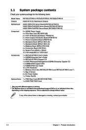
1.2 Serial number label Before requesting support from the ASUS Technical Support team, you must take note of the product, ASUS Technical Support team members can then offer a quicker and satisfying solution to your problems. RS720Q-E7/RS12 xxS0xxxxxxxxxx ASUS RS720Q-E7/RS12, RS724Q-E7/RS12, RS726Q-E7/RS12 1-3 With the correct serial number of the product's serial number containing 14 characters such as xxS0xxxxxxxxxx. See the figure below.
1.2 Serial number label Before requesting support from the ASUS Technical Support team, you must take note of the product, ASUS Technical Support team members can then offer a quicker and satisfying solution to your problems. RS720Q-E7/RS12 xxS0xxxxxxxxxx ASUS RS720Q-E7/RS12, RS724Q-E7/RS12, RS726Q-E7/RS12 1-3 With the correct serial number of the product's serial number containing 14 characters such as xxS0xxxxxxxxxx. See the figure below.
RS72xQ-E7_RS12 User Manual
Page 14
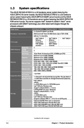
...; The server supports Intel® Socket-R LGA2011 Xeon® series processors with EM64T technology, plus other latest technologies through the chipsets onboard. the ASUS RS724Q-E7/RS12 is a 2U barebone server system featuring the ASUS Z9PH-D16/QDR server boards and the ASUS RS726Q-E7/RS12 is a 2U barebone server system featuring the ASUS Z9PH-D16/ FDR server boards.
...; The server supports Intel® Socket-R LGA2011 Xeon® series processors with EM64T technology, plus other latest technologies through the chipsets onboard. the ASUS RS724Q-E7/RS12 is a 2U barebone server system featuring the ASUS Z9PH-D16/QDR server boards and the ASUS RS726Q-E7/RS12 is a 2U barebone server system featuring the ASUS Z9PH-D16/ FDR server boards.
RS72xQ-E7_RS12 User Manual
Page 15
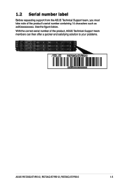
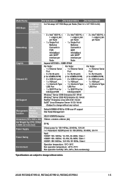
Model Name RS726Q-E7/RS12 RS724Q-E7/RS12 RS720Q-E7/RS12 HDD Bays I = internal A or S will be hotswappable Networking LAN 3 x Hot-swap 3.5" HDD Bays per Node (Total 12 x 3.5" ... x Internal A Type USB Port Out of Band Management Remote Solution Hardware Software Default ASMB6-iKVM for KVM-over-IP support Intel Node Management ASUS ASWM Enterprise Dimension (HH x WW x DD) 756mm x 444mm x 88mm (2U) Net Weight Kg (CPU, DRAM & HDD not ... humidity: 20%-90% ( Non-condensing) *Specifications are subject to change without notice. ASUS RS720Q-E7/RS12, RS724Q-E7/RS12, RS726Q-E7/RS12 1-5
Model Name RS726Q-E7/RS12 RS724Q-E7/RS12 RS720Q-E7/RS12 HDD Bays I = internal A or S will be hotswappable Networking LAN 3 x Hot-swap 3.5" HDD Bays per Node (Total 12 x 3.5" ... x Internal A Type USB Port Out of Band Management Remote Solution Hardware Software Default ASMB6-iKVM for KVM-over-IP support Intel Node Management ASUS ASWM Enterprise Dimension (HH x WW x DD) 756mm x 444mm x 88mm (2U) Net Weight Kg (CPU, DRAM & HDD not ... humidity: 20%-90% ( Non-condensing) *Specifications are subject to change without notice. ASUS RS720Q-E7/RS12, RS724Q-E7/RS12, RS726Q-E7/RS12 1-5
RS72xQ-E7_RS12 User Manual
Page 17
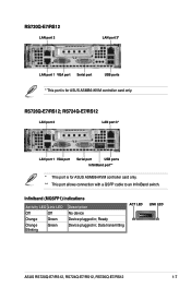
... Device plugged in ; Ready Device plugged in ; Data transmitting ACT LED LINK LED ASUS RS720Q-E7/RS12, RS724Q-E7/RS12, RS726Q-E7/RS12 1-7 RS726Q-E7/RS12; RS720Q-E7/RS12 LAN port 2 LAN port 3* LAN port 1 VGA port Serial port USB ports * This port is for ASUS ASMB6-iKVM controller card only. RS724Q-E7/RS12 LAN port 2 LAN port 3* LAN port 1 VGA port Serial port USB ports...
... Device plugged in ; Ready Device plugged in ; Data transmitting ACT LED LINK LED ASUS RS720Q-E7/RS12, RS724Q-E7/RS12, RS726Q-E7/RS12 1-7 RS726Q-E7/RS12; RS720Q-E7/RS12 LAN port 2 LAN port 3* LAN port 1 VGA port Serial port USB ports * This port is for ASUS ASMB6-iKVM controller card only. RS724Q-E7/RS12 LAN port 2 LAN port 3* LAN port 1 VGA port Serial port USB ports...
RS72xQ-E7_RS12 User Manual
Page 18
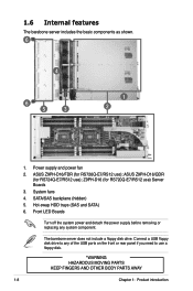
...4 6 5 3 1 2 1. SATA/SAS backplane (hidden) 5. System fans 4. The barebone server does not include a floppy disk drive. Z9PH-D16 (for RS724Q-E7/RS12 use ) Server Boards 3. Connect a USB floppy disk drive to use ); Front LED Boards Turn off the system power and detach the power supply before removing...front or rear panel if you need to any system component. ASUS Z9PH-D16/QDR (for RS720Q-E7/RS12 use ); Hot-swap HDD trays (SAS and SATA) 6. Power supply and power fan 2. ASUS Z9PH-D16/FDR (for RS726Q-E7/RS12 use a floppy disk. *WARNING HAZARDOUS MOVING PARTS KEEP FINGERS ...
...4 6 5 3 1 2 1. SATA/SAS backplane (hidden) 5. System fans 4. The barebone server does not include a floppy disk drive. Z9PH-D16 (for RS724Q-E7/RS12 use ) Server Boards 3. Connect a USB floppy disk drive to use ); Front LED Boards Turn off the system power and detach the power supply before removing...front or rear panel if you need to any system component. ASUS Z9PH-D16/QDR (for RS720Q-E7/RS12 use ); Hot-swap HDD trays (SAS and SATA) 6. Power supply and power fan 2. ASUS Z9PH-D16/FDR (for RS726Q-E7/RS12 use a floppy disk. *WARNING HAZARDOUS MOVING PARTS KEEP FINGERS ...
RS72xQ-E7_RS12 User Manual
Page 19
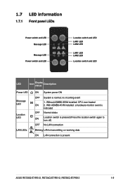
... switch and LED LED Icon Display status Description Power LED Message LED Location LED LAN LEDs ON System power ON OFF System is present ASUS RS720Q-E7/RS12, RS724Q-E7/RS12, RS726Q-E7/RS12 1-9 With ASMB6-iKVM installed: a hardware monitor event is indicated OFF Normal status ON Location switch is pressed (Press the location switch again to turn...
... switch and LED LED Icon Display status Description Power LED Message LED Location LED LAN LEDs ON System power ON OFF System is present ASUS RS720Q-E7/RS12, RS724Q-E7/RS12, RS726Q-E7/RS12 1-9 With ASMB6-iKVM installed: a hardware monitor event is indicated OFF Normal status ON Location switch is pressed (Press the location switch again to turn...
RS72xQ-E7_RS12 User Manual
Page 23
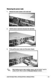
Firmly pull the server node out of the server chassis. Refer to node slot number 1 and 3 or number 2 and 4. Removing the server node 1. Hold the server node lever and press the node latch. 3. ASUS RS720Q-E7/RS12, RS724Q-E7/RS12, RS726Q-E7/RS12 2-3 Remove the screw located on the node latch. 2. When installing only two nodes, install the nodes to section 1.5 Rear panel features for details.
Firmly pull the server node out of the server chassis. Refer to node slot number 1 and 3 or number 2 and 4. Removing the server node 1. Hold the server node lever and press the node latch. 3. ASUS RS720Q-E7/RS12, RS724Q-E7/RS12, RS726Q-E7/RS12 2-3 Remove the screw located on the node latch. 2. When installing only two nodes, install the nodes to section 1.5 Rear panel features for details.
RS72xQ-E7_RS12 User Manual
Page 25
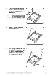
Load lever 3. Slightly lift the load lever in the direction of the arrow. 4. Press the right load lever with your thumb (C), then move it to the left load lever with your thumb (A), then move it to the socket pins, do not remove the PnP cap unless you are installing a CPU. A B To prevent damage to the right (D) until it is released from the retention tab. E C D ASUS RS720Q-E7/RS12, RS724Q-E7/RS12, RS726Q-E7/RS12 2-5 Lift the load lever in the direction of the arrow (E). 2. Press the left (B) until it is released from the retention tab.
Load lever 3. Slightly lift the load lever in the direction of the arrow. 4. Press the right load lever with your thumb (C), then move it to the left load lever with your thumb (A), then move it to the socket pins, do not remove the PnP cap unless you are installing a CPU. A B To prevent damage to the right (D) until it is released from the retention tab. E C D ASUS RS720Q-E7/RS12, RS724Q-E7/RS12, RS726Q-E7/RS12 2-5 Lift the load lever in the direction of the arrow (E). 2. Press the left (B) until it is released from the retention tab.
RS72xQ-E7_RS12 User Manual
Page 27
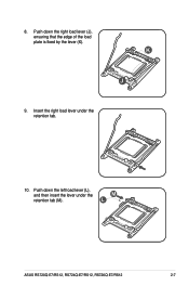
K J 9. M L ASUS RS720Q-E7/RS12, RS724Q-E7/RS12, RS726Q-E7/RS12 2-7 Insert the right load lever under the retention tab (M). Push down the left load lever (L), and then insert the lever under the retention tab. 10. Push down the right load lever (J), ensuring that the edge of the load plate is fixed by the lever (K). 8.
K J 9. M L ASUS RS720Q-E7/RS12, RS724Q-E7/RS12, RS726Q-E7/RS12 2-7 Insert the right load lever under the retention tab (M). Push down the left load lever (L), and then insert the lever under the retention tab. 10. Push down the right load lever (J), ensuring that the edge of the load plate is fixed by the lever (K). 8.
RS72xQ-E7_RS12 User Manual
Page 29
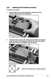
Twist each of the installed CPU, ensuring that the four fasteners match the holes on the motherboard. 2. ASUS RS720Q-E7/RS12, RS724Q-E7/RS12, RS726Q-E7/RS12 2-9 2.2.2 Installing the CPU heatsink and airduct To install the CPU heatsink: 1. When the four screws are attached, tighten them one by one to the motherboard. Place the heatsink on top of the four screws with a Philips (cross) screwdriver just enough to attach the heatsink to completely secure the heatsink. A B B A Tighten the four heatsink screws in a diagonal sequence.
Twist each of the installed CPU, ensuring that the four fasteners match the holes on the motherboard. 2. ASUS RS720Q-E7/RS12, RS724Q-E7/RS12, RS726Q-E7/RS12 2-9 2.2.2 Installing the CPU heatsink and airduct To install the CPU heatsink: 1. When the four screws are attached, tighten them one by one to the motherboard. Place the heatsink on top of the four screws with a Philips (cross) screwdriver just enough to attach the heatsink to completely secure the heatsink. A B B A Tighten the four heatsink screws in a diagonal sequence.
RS72xQ-E7_RS12 User Manual
Page 31
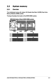
The figure illustrates the location of the DDR3 DIMM sockets: ASUS RS720Q-E7/RS12, RS724Q-E7/RS12, RS726Q-E7/RS12 2-11 2.3 System memory 2.3.1 Overview The motherboard comes with sixteen (16) Double Data Rate 3 (DDR3) Dual Inline Memory Modules (DIMM) sockets.
The figure illustrates the location of the DDR3 DIMM sockets: ASUS RS720Q-E7/RS12, RS724Q-E7/RS12, RS726Q-E7/RS12 2-11 2.3 System memory 2.3.1 Overview The motherboard comes with sixteen (16) Double Data Rate 3 (DDR3) Dual Inline Memory Modules (DIMM) sockets.
RS72xQ-E7_RS12 User Manual
Page 33
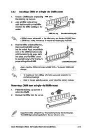
... slot key 1 Unlocked retaining clip A DIMM is keyed with extra force. Press the retaining clip outward to ensure proper sitting of the memory modules. ASUS RS720Q-E7/RS12, RS724Q-E7/RS12, RS726Q-E7/RS12 2-13 Unlock a DIMM socket by both ends of the DIMM simultaneously until the retaining clip snaps back into place, and the DIMM cannot be...
... slot key 1 Unlocked retaining clip A DIMM is keyed with extra force. Press the retaining clip outward to ensure proper sitting of the memory modules. ASUS RS720Q-E7/RS12, RS724Q-E7/RS12, RS726Q-E7/RS12 2-13 Unlock a DIMM socket by both ends of the DIMM simultaneously until the retaining clip snaps back into place, and the DIMM cannot be...
RS72xQ-E7_RS12 User Manual
Page 35
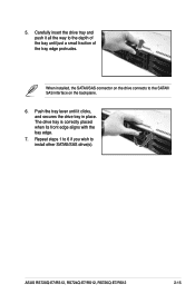
Push the tray lever until just a small fraction of the bay until it clicks, and secures the drive tray in place. Carefully insert the drive tray and push it all the way to the depth of the tray edge protrudes. When installed, the SATAII/SAS connector on the drive connects to install other SATAII/SAS drive(s). ASUS RS720Q-E7/RS12, RS724Q-E7/RS12, RS726Q-E7/RS12 2-15 The drive tray is correctly placed when its front edge aligns with the bay edge. 7. 5. Repeat steps 1 to 6 if you wish to the SATAII/ SAS interface on the backplane. 6.
Push the tray lever until just a small fraction of the bay until it clicks, and secures the drive tray in place. Carefully insert the drive tray and push it all the way to the depth of the tray edge protrudes. When installed, the SATAII/SAS connector on the drive connects to install other SATAII/SAS drive(s). ASUS RS720Q-E7/RS12, RS724Q-E7/RS12, RS726Q-E7/RS12 2-15 The drive tray is correctly placed when its front edge aligns with the bay edge. 7. 5. Repeat steps 1 to 6 if you wish to the SATAII/ SAS interface on the backplane. 6.
RS72xQ-E7_RS12 User Manual
Page 37
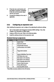
... 0 1 System Timer 1 2 Keyboard Controller 2 - See Chapter 5 for information on the system and change the necessary BIOS settings, if any. Assign an IRQ to the card. ASUS RS720Q-E7/RS12, RS724Q-E7/RS12, RS726Q-E7/RS12 2-17 5.
... 0 1 System Timer 1 2 Keyboard Controller 2 - See Chapter 5 for information on the system and change the necessary BIOS settings, if any. Assign an IRQ to the card. ASUS RS720Q-E7/RS12, RS724Q-E7/RS12, RS726Q-E7/RS12 2-17 5.
RS72xQ-E7_RS12 User Manual
Page 39
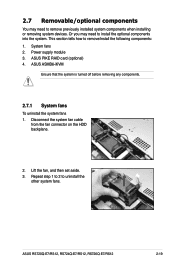
... any components. 2.7.1 System fans To uninstall the system fans 1. Repeat step 1 to 2 to remove/install the following components: 1. ASUS RS720Q-E7/RS12, RS724Q-E7/RS12, RS726Q-E7/RS12 2-19 This section tells how to uninstall the other system fans. ASUS PIKE RAID card (optional) 4. Disconnect the system fan cable from the fan connector on the HDD backplane. 2. Power supply...
... any components. 2.7.1 System fans To uninstall the system fans 1. Repeat step 1 to 2 to remove/install the following components: 1. ASUS RS720Q-E7/RS12, RS724Q-E7/RS12, RS726Q-E7/RS12 2-19 This section tells how to uninstall the other system fans. ASUS PIKE RAID card (optional) 4. Disconnect the system fan cable from the fan connector on the HDD backplane. 2. Power supply...
RS72xQ-E7_RS12 User Manual
Page 41
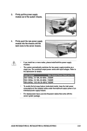
... module into the chassis until the latch locks to the table below for details. The combined output power varies with the server system package. ASUS RS720Q-E7/RS12, RS724Q-E7/RS12, RS726Q-E7/RS12 2-21 Input Voltage Max. Firmly pull the power supply module out of an individual power supply module. • For steady power input, use only...
... module into the chassis until the latch locks to the table below for details. The combined output power varies with the server system package. ASUS RS720Q-E7/RS12, RS724Q-E7/RS12, RS726Q-E7/RS12 2-21 Input Voltage Max. Firmly pull the power supply module out of an individual power supply module. • For steady power input, use only...
RS72xQ-E7_RS12 User Manual
Page 43
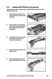
... as shown in the right figure. 2. Remove the three screws on the PIKE riser card. 5. 2.7.4 Installing ASUS PIKE Riser Card (optional) Follow the steps below to install the optional ASUS PIKE SAS RAID card to the riser card bracket with two screws. Secure the PIKE riser card to the... ASUS PIKE riser card. 1. Firmly hold the riser card bracket, and then pull it up to detach it from the bracket. 4. ASUS RS720Q-E7/RS12, RS724Q-E7/RS12, RS726Q-E7/RS12 2-23 Locate the two screws on the riser card bracket, then remove...
... as shown in the right figure. 2. Remove the three screws on the PIKE riser card. 5. 2.7.4 Installing ASUS PIKE Riser Card (optional) Follow the steps below to install the optional ASUS PIKE SAS RAID card to the riser card bracket with two screws. Secure the PIKE riser card to the... ASUS PIKE riser card. 1. Firmly hold the riser card bracket, and then pull it up to detach it from the bracket. 4. ASUS RS720Q-E7/RS12, RS724Q-E7/RS12, RS726Q-E7/RS12 2-23 Locate the two screws on the riser card bracket, then remove...
RS72xQ-E7_RS12 User Manual
Page 45
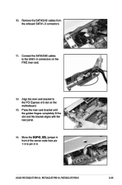
10. Move the SGPIO_SEL jumper in front of the server node from the onboard SATA1-3 connectors. 11. Connect the SATA/SAS cables to the SAS1-3 connectors on the motherboard. 13. Align the riser card bracket to pin 2-3. Press the riser card bracket until the golden fingers completely fit the slot and the bracket aligns with the rear panel. 14. ASUS RS720Q-E7/RS12, RS724Q-E7/RS12, RS726Q-E7/RS12 2-25 Remove the SATA/SAS cables from pin 1-2 to the PCI Express x16 slot on the PIKE riser card. 12.
10. Move the SGPIO_SEL jumper in front of the server node from the onboard SATA1-3 connectors. 11. Connect the SATA/SAS cables to the SAS1-3 connectors on the motherboard. 13. Align the riser card bracket to pin 2-3. Press the riser card bracket until the golden fingers completely fit the slot and the bracket aligns with the rear panel. 14. ASUS RS720Q-E7/RS12, RS724Q-E7/RS12, RS726Q-E7/RS12 2-25 Remove the SATA/SAS cables from pin 1-2 to the PCI Express x16 slot on the PIKE riser card. 12.
RS72xQ-E7_RS12 User Manual
Page 49
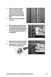
... consists of the rail with two thin lips on the bottom thin lip of the front mounting hole, as shown in the right figure. 7. ASUS RS720Q-E7/RS12, RS724Q-E7/RS12, RS726Q-E7/RS12 3-3 Repeat step 4 to 7 to install the rack rail. Secure the front and rear ends of three square mounting holes with two rack screws and...
... consists of the rail with two thin lips on the bottom thin lip of the front mounting hole, as shown in the right figure. 7. ASUS RS720Q-E7/RS12, RS724Q-E7/RS12, RS726Q-E7/RS12 3-3 Repeat step 4 to 7 to install the rack rail. Secure the front and rear ends of three square mounting holes with two rack screws and...


