User Guide
Page 11
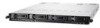
ASUS RS700DA-E6/PS4, RS704DA-E6/PS4 Product introduction Chapter 1 This chapter describes the general features of the server, including sections on front panel and rear panel specifications.
ASUS RS700DA-E6/PS4, RS704DA-E6/PS4 Product introduction Chapter 1 This chapter describes the general features of the server, including sections on front panel and rear panel specifications.

User Guide
Page 12
... 3.5" HDD trays (by region) 1 x SAS/SATA2 Backplane (ASUS BP4LX-R12C) 2 x PCI Riser Card (ASUS RE16R-R12B) 2 x Front I/O Board (ASUS FPB-AR14) 1 x Power Supply Power Distribution Board (ASUS PDB-R12C) 8 x System Fans (40mm x 56mm) Accessories 1 x RS700DA-E6/PS4, RS704DA-E6/PS4 User's Guide 1 x ASUS ASWM 2.0 User's Guide 1 x RS700DA-E6/PS4, RS704DA-E6/PS4 Support CD (including ASWM*) 1 x Mellanox driver disc (RS704DA-E6/PS4 only**) 1 x Bag of Screws 1 x AC Power...
... 3.5" HDD trays (by region) 1 x SAS/SATA2 Backplane (ASUS BP4LX-R12C) 2 x PCI Riser Card (ASUS RE16R-R12B) 2 x Front I/O Board (ASUS FPB-AR14) 1 x Power Supply Power Distribution Board (ASUS PDB-R12C) 8 x System Fans (40mm x 56mm) Accessories 1 x RS700DA-E6/PS4, RS704DA-E6/PS4 User's Guide 1 x ASUS ASWM 2.0 User's Guide 1 x RS700DA-E6/PS4, RS704DA-E6/PS4 Support CD (including ASWM*) 1 x Mellanox driver disc (RS704DA-E6/PS4 only**) 1 x Bag of Screws 1 x AC Power...

User Guide
Page 13
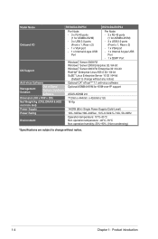
1.3 System specifications The ASUS RS700DA-E6/PS4 is a 1U barebone server system featuring the ASUS KGMH-D16/QDR server board. The ASUS RS704DA-E6/PS4 is a 1U barebone server system featuring the ASUS KGNH-D16 server board. The servers support AMD® Socket G34 (LGA1944) Opteron™ 6100 series processors, plus other latest technologies through the chipsets... (RDIMM) per Node Maximum up to 64GB (UDIMM) per Node DDR3 800 / 1066 / 1333 UDIMM with QSFP interface (continued on the next page) ASUS RS700DA-E6/PS4, RS704DA-E6/PS4 1-3 Infiniband MT25408B0- AMD® SR5670 -
1.3 System specifications The ASUS RS700DA-E6/PS4 is a 1U barebone server system featuring the ASUS KGMH-D16/QDR server board. The ASUS RS704DA-E6/PS4 is a 1U barebone server system featuring the ASUS KGNH-D16 server board. The servers support AMD® Socket G34 (LGA1944) Opteron™ 6100 series processors, plus other latest technologies through the chipsets... (RDIMM) per Node Maximum up to 64GB (UDIMM) per Node DDR3 800 / 1066 / 1333 UDIMM with QSFP interface (continued on the next page) ASUS RS700DA-E6/PS4, RS704DA-E6/PS4 1-3 Infiniband MT25408B0- AMD® SR5670 -
User Guide
Page 14
Model Name RS700DA-E6/PS4 RS704DA-E6/PS4 Onboard I/O OS Support Anti-virus Software Per Node: Per Node: - 3 x RJ-45 ports - 3 x RJ-45 ports (1 for ASMB4-iKVM) (1 for ASMB4-iKVM) - 3 x USB 2.0 ports - 3 x USB 2.0 ... notice) Optional CA® eTrust™ 7.1 anti-virus software Management Solution Out of Band Remote Hardware Software Optional ASMB4-iKVM for KVM-over-IP support ASUS ASWM 2.0 Dimension (HH x WW x DD) 712mm x 444mm x 43.6mm (1U) Net Weight Kg (CPU, DRAM & HDD not inclu ded) 18 Kg Power Supply 1400W (80...
Model Name RS700DA-E6/PS4 RS704DA-E6/PS4 Onboard I/O OS Support Anti-virus Software Per Node: Per Node: - 3 x RJ-45 ports - 3 x RJ-45 ports (1 for ASMB4-iKVM) (1 for ASMB4-iKVM) - 3 x USB 2.0 ports - 3 x USB 2.0 ... notice) Optional CA® eTrust™ 7.1 anti-virus software Management Solution Out of Band Remote Hardware Software Optional ASMB4-iKVM for KVM-over-IP support ASUS ASWM 2.0 Dimension (HH x WW x DD) 712mm x 444mm x 43.6mm (1U) Net Weight Kg (CPU, DRAM & HDD not inclu ded) 18 Kg Power Supply 1400W (80...
User Guide
Page 15
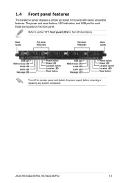
The power and reset buttons, LED indicators, and USB port for the LED descriptions. ASUS RS700DA-E6/PS4, RS704DA-E6/PS4 1-5 1.4 Front panel features The barebone server displays a simple yet stylish front panel with easily accessible features. Refer to section 1.7.1 Front panel LEDs for each Node ...
The power and reset buttons, LED indicators, and USB port for the LED descriptions. ASUS RS700DA-E6/PS4, RS704DA-E6/PS4 1-5 1.4 Front panel features The barebone server displays a simple yet stylish front panel with easily accessible features. Refer to section 1.7.1 Front panel LEDs for each Node ...
User Guide
Page 16
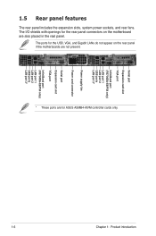
... ports LAN port 3* Power supply fan Power cord connector Serial port Expansion card slot VGA port InfiniBand port (RS704DA-E6/PS4 only) LAN port 1 LAN port 2 USB ports LAN port 3* 1-6 Chapter 1: Product introduction The ports for ASUS ASMB4-iKVM controller cards only. 1.5 Rear panel features The rear panel includes the expansion slots, system power...
... ports LAN port 3* Power supply fan Power cord connector Serial port Expansion card slot VGA port InfiniBand port (RS704DA-E6/PS4 only) LAN port 1 LAN port 2 USB ports LAN port 3* 1-6 Chapter 1: Product introduction The ports for ASUS ASMB4-iKVM controller cards only. 1.5 Rear panel features The rear panel includes the expansion slots, system power...
User Guide
Page 17
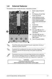
.../QDR server board (RS704DA-E6/ PS4) 4. The barebone server does not include a floppy disk drive and an optical disc drive. PCI Express x16 slot Riser Cards (at x16 link) 3. SATA/SAS backplane (hidden) 6/7. ASUS KGHN-D16 server board (RS700DA-E6/PS4); Connect to SATA port 1/2 of Right-System. 10. Hot-swap...USB ODD to use a floppy disk or a optical disc. *WARNING HAZARDOUS MOVING PARTS KEEP FINGERS AND OTHER BODY PARTS AWAY ASUS RS700DA-E6/PS4, RS704DA-E6/PS4 1-7 Connect to the system cover before turning on the front or rear panel if you need to any system component.
.../QDR server board (RS704DA-E6/ PS4) 4. The barebone server does not include a floppy disk drive and an optical disc drive. PCI Express x16 slot Riser Cards (at x16 link) 3. SATA/SAS backplane (hidden) 6/7. ASUS KGHN-D16 server board (RS700DA-E6/PS4); Connect to SATA port 1/2 of Right-System. 10. Hot-swap...USB ODD to use a floppy disk or a optical disc. *WARNING HAZARDOUS MOVING PARTS KEEP FINGERS AND OTHER BODY PARTS AWAY ASUS RS700DA-E6/PS4, RS704DA-E6/PS4 1-7 Connect to the system cover before turning on the front or rear panel if you need to any system component.
User Guide
Page 19
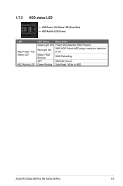
1.7.3 HDD status LED HDD Power / Fail Status LED (Green/Red) HDD Activity LED (Green) LED HDD Power / Fail Status LED HDD Activity LED LED Status Description Green Light ON Power ON (Detection HDD Present) Red Light ON RAID HDD Failed (HDD plug-in ready but detection error) Green / Red Blinking RAID Rebuilding OFF HDD Not Found Green Blinking Data Read / Write to HDD ASUS RS700DA-E6/PS4, RS704DA-E6/PS4 1-9
1.7.3 HDD status LED HDD Power / Fail Status LED (Green/Red) HDD Activity LED (Green) LED HDD Power / Fail Status LED HDD Activity LED LED Status Description Green Light ON Power ON (Detection HDD Present) Red Light ON RAID HDD Failed (HDD plug-in ready but detection error) Green / Red Blinking RAID Rebuilding OFF HDD Not Found Green Blinking Data Read / Write to HDD ASUS RS700DA-E6/PS4, RS704DA-E6/PS4 1-9
User Guide
Page 21
ASUS RS700DA-E6/PS4, RS704DA-E6/PS4 Hardware setup Chapter 2 This chapter lists the hardware setup procedures that you have to perform when installing or removing system components.
ASUS RS700DA-E6/PS4, RS704DA-E6/PS4 Hardware setup Chapter 2 This chapter lists the hardware setup procedures that you have to perform when installing or removing system components.
User Guide
Page 23
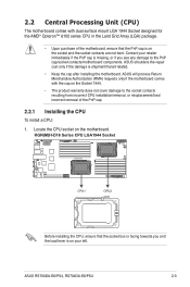
...if the damage is on your retailer immediately if the PnP cap is on the socket and the socket contacts are not bent. ASUS will process Return Merchandise Authorization (RMA) requests only if the motherboard comes with dual surface mount LGA 1944 Socket designed for the... Upon purchase of the PnP cap. 2.2.1 Installing the CPU To install a CPU: 1. Contact your left. Locate the CPU socket on the motherboard. ASUS RS700DA-E6/PS4, RS704DA-E6/PS4 2-3 2.2 Central Processing Unit (CPU) The motherboard comes with the cap on the Socket 1944. • The product warranty does not cover damage to...
...if the damage is on your retailer immediately if the PnP cap is on the socket and the socket contacts are not bent. ASUS will process Return Merchandise Authorization (RMA) requests only if the motherboard comes with dual surface mount LGA 1944 Socket designed for the... Upon purchase of the PnP cap. 2.2.1 Installing the CPU To install a CPU: 1. Contact your left. Locate the CPU socket on the motherboard. ASUS RS700DA-E6/PS4, RS704DA-E6/PS4 2-3 2.2 Central Processing Unit (CPU) The motherboard comes with the cap on the Socket 1944. • The product warranty does not cover damage to...
User Guide
Page 25
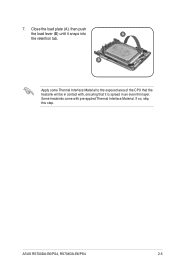
ASUS RS700DA-E6/PS4, RS704DA-E6/PS4 2-5 7. B Apply some Thermal Interface Material to the exposed area of the CPU that the heatsink will be in an even thin layer. If so, skip this step. Some heatsinks come with , ensuring that it snaps into A the retention tab. Close the load plate (A), then push the load lever (B) until it is spread in contact with pre-applied Thermal Interface Material.
ASUS RS700DA-E6/PS4, RS704DA-E6/PS4 2-5 7. B Apply some Thermal Interface Material to the exposed area of the CPU that the heatsink will be in an even thin layer. If so, skip this step. Some heatsinks come with , ensuring that it snaps into A the retention tab. Close the load plate (A), then push the load lever (B) until it is spread in contact with pre-applied Thermal Interface Material.
User Guide
Page 27
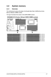
2.3 System memory 2.3.1 Overview The motherboard comes with sixteen (16) Double Data Rate 3 (DDR3) Dual Inline Memory Modules (DIMM) sockets. The figure illustrates the location of the DDR3 DIMM sockets: ASUS RS700DA-E6/PS4, RS704DA-E6/PS4 2-7
2.3 System memory 2.3.1 Overview The motherboard comes with sixteen (16) Double Data Rate 3 (DDR3) Dual Inline Memory Modules (DIMM) sockets. The figure illustrates the location of the DDR3 DIMM sockets: ASUS RS700DA-E6/PS4, RS704DA-E6/PS4 2-7
User Guide
Page 29
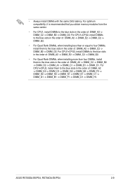
... than or equal to four DIMMs, install them to the blue slots in the order of : DIMM_A2 -> DIMM_C2 -> DIMM_B2 -> DIMM_D2 -> DIMM_A1 -> DIMM_C1 -> DIMM_B1 -> DIMM_D1. ASUS RS700DA-E6/PS4, RS704DA-E6/PS4 2-9 For CPU1+CPU2, install them to the blue slots in the order of : DIMM_A2 -> DIMM_C2 -> DIMM_B2 -> DIMM_D2. For optimum compatibility, it is recommended that you...
... than or equal to four DIMMs, install them to the blue slots in the order of : DIMM_A2 -> DIMM_C2 -> DIMM_B2 -> DIMM_D2 -> DIMM_A1 -> DIMM_C1 -> DIMM_B1 -> DIMM_D1. ASUS RS700DA-E6/PS4, RS704DA-E6/PS4 2-9 For CPU1+CPU2, install them to the blue slots in the order of : DIMM_A2 -> DIMM_C2 -> DIMM_B2 -> DIMM_D2. For optimum compatibility, it is recommended that you...
User Guide
Page 31
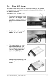
...-swap SATAII/SAS HDD: spring lock 1. Release a drive tray by pushing the spring lock to the motherboard SATAII/SAS ports via the SATAII/SAS backplane. ASUS RS700DA-E6/PS4, RS704DA-E6/PS4 2-11 Take note of hard disk drives. Each side has three holes to secure the hard disk drive. 4. Place a SATAII/SAS hard disk drive...
...-swap SATAII/SAS HDD: spring lock 1. Release a drive tray by pushing the spring lock to the motherboard SATAII/SAS ports via the SATAII/SAS backplane. ASUS RS700DA-E6/PS4, RS704DA-E6/PS4 2-11 Take note of hard disk drives. Each side has three holes to secure the hard disk drive. 4. Place a SATAII/SAS hard disk drive...
User Guide
Page 33
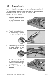
... motherboard. 2. Firmly hold the riser card bracket, and then pull it up to the bracket as shown, and then secure the card with a screw. ASUS RS700DA-E6/PS4, RS704DA-E6/PS4 2-13 Press the riser card bracket until the golden connectors completely fit the slot and the bracket aligns with a riser card bracket. You need to...
... motherboard. 2. Firmly hold the riser card bracket, and then pull it up to the bracket as shown, and then secure the card with a screw. ASUS RS700DA-E6/PS4, RS704DA-E6/PS4 2-13 Press the riser card bracket until the golden connectors completely fit the slot and the bracket aligns with a riser card bracket. You need to...
User Guide
Page 35
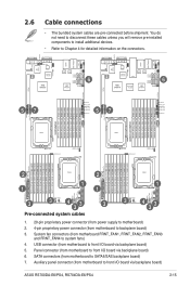
.../SAS backplane board) 7. 2.6 Cable connections • The bundled system cables are pre-connected before shipment. USB connector (from motherboard to front I /O board via backplane board) ASUS RS700DA-E6/PS4, RS704DA-E6/PS4 2-15
.../SAS backplane board) 7. 2.6 Cable connections • The bundled system cables are pre-connected before shipment. USB connector (from motherboard to front I /O board via backplane board) ASUS RS700DA-E6/PS4, RS704DA-E6/PS4 2-15
User Guide
Page 37
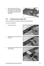
ASUS RS700DA-E6/PS4, RS704DA-E6/PS4 2-17 Lift up the PSU lever. 2. Firmly pull the failed PSU out of the server chassis. To remove the failed PSU 1. Hold the PSU lever and press the PSU latch. 3. 3. Press down gently on the location above the system fans to ensure proper fan installation, as shown in the right figure. 2.7.2 Replacing power supply units Follow the steps below to replace the failed power supply unit (PSU). Recover the rear cover.
ASUS RS700DA-E6/PS4, RS704DA-E6/PS4 2-17 Lift up the PSU lever. 2. Firmly pull the failed PSU out of the server chassis. To remove the failed PSU 1. Hold the PSU lever and press the PSU latch. 3. 3. Press down gently on the location above the system fans to ensure proper fan installation, as shown in the right figure. 2.7.2 Replacing power supply units Follow the steps below to replace the failed power supply unit (PSU). Recover the rear cover.
User Guide
Page 39
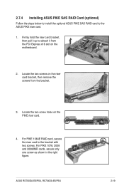
Firmly hold the riser card bracket, then pull it up to the ASUS PIKE riser card. 1. ASUS RS700DA-E6/PS4, RS704DA-E6/PS4 2-19 2.7.4 Installing ASUS PIKE SAS RAID Card (optional) Follow the steps below to install the optional ASUS PIKE SAS RAID card to detach it from the bracket. 3. Locate the two screws on the PIKE riser card. 4. Locate...
Firmly hold the riser card bracket, then pull it up to the ASUS PIKE riser card. 1. ASUS RS700DA-E6/PS4, RS704DA-E6/PS4 2-19 2.7.4 Installing ASUS PIKE SAS RAID Card (optional) Follow the steps below to install the optional ASUS PIKE SAS RAID card to detach it from the bracket. 3. Locate the two screws on the PIKE riser card. 4. Locate...
User Guide
Page 41
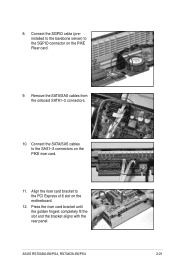
Connect the SGPIO cable (preinstalled to the barebone server) to the SGPIO connector on the motherboard. 12. Align the riser card bracket to the SAS1-2 connectors on the PIKE riser card. 11. Press the riser card bracket until the golden fingers completely fit the slot and the bracket aligns with the rear panel. Connect the SATA/SAS cables to the PCI Express x16 slot on the PIKE Riser card. 9. Remove the SATA/SAS cables from the onboard SATA1-2 connectors. 10. 8. ASUS RS700DA-E6/PS4, RS704DA-E6/PS4 2-21
Connect the SGPIO cable (preinstalled to the barebone server) to the SGPIO connector on the motherboard. 12. Align the riser card bracket to the SAS1-2 connectors on the PIKE riser card. 11. Press the riser card bracket until the golden fingers completely fit the slot and the bracket aligns with the rear panel. Connect the SATA/SAS cables to the PCI Express x16 slot on the PIKE Riser card. 9. Remove the SATA/SAS cables from the onboard SATA1-2 connectors. 10. 8. ASUS RS700DA-E6/PS4, RS704DA-E6/PS4 2-21
User Guide
Page 43
Installation options Chapter 3 This chapter describes how to install the optional components and devices into the barebone server. ASUS RS700DA-E6/PS4, RS704DA-E6/PS4
Installation options Chapter 3 This chapter describes how to install the optional components and devices into the barebone server. ASUS RS700DA-E6/PS4, RS704DA-E6/PS4


