User Guide
Page 4
... 3-2 3.3 Attaching the rack rails 3-3 3.4 Rackmounting the server 3-4 Chapter 4: Motherboard Info 4.1 Motherboard layout 4-2 4.2 Jumpers 4-6 4.3 Internal connectors 4-12 4.4 Internal LEDs 4-20 Chapter 5: BIOS setup 5.1 Managing and updating your BIOS 5-2 5.1.1 AFUDOS utility 5-2 5.1.2 ASUS CrashFree BIOS 3 utility 5-4 5.2 BIOS setup program 5-5 5.2.1 BIOS menu screen 5-6 5.2.2 Menu bar 5-6 5.2.3 Navigation keys 5-6 5.2.4 Menu items 5-7 5.2.5 Sub-menu items 5-7 5.2.6 Configuration fields 5-7 5.2.7 Pop-up window 5-7 5.2.8 Scroll bar 5-7 5.2.9 General...
... 3-2 3.3 Attaching the rack rails 3-3 3.4 Rackmounting the server 3-4 Chapter 4: Motherboard Info 4.1 Motherboard layout 4-2 4.2 Jumpers 4-6 4.3 Internal connectors 4-12 4.4 Internal LEDs 4-20 Chapter 5: BIOS setup 5.1 Managing and updating your BIOS 5-2 5.1.1 AFUDOS utility 5-2 5.1.2 ASUS CrashFree BIOS 3 utility 5-4 5.2 BIOS setup program 5-5 5.2.1 BIOS menu screen 5-6 5.2.2 Menu bar 5-6 5.2.3 Navigation keys 5-6 5.2.4 Menu items 5-7 5.2.5 Sub-menu items 5-7 5.2.6 Configuration fields 5-7 5.2.7 Pop-up window 5-7 5.2.8 Scroll bar 5-7 5.2.9 General...

User Guide
Page 5
... 5.6.4 Security 5-34 5.7 Exit menu 5-36 Chapter 6: RAID configuration 6.1 Setting up RAID 6-2 6.1.1 RAID definitions 6-2 6.1.2 Installing hard disk drives 6-2 6.1.3 RAID controller selection 6-3 6.1.4 Setting the RAID item in BIOS 6-3 6.2 LSI Software RAID Configuration Utility 6-4 6.2.1 Creating a RAID set 6-5 6.2.2 Adding or viewing a RAID configuration 6-11 6.2.3 Initializing the virtual drives 6-12 6.2.4 Rebuilding failed drives 6-16 6.2.5 Checking the...
... 5.6.4 Security 5-34 5.7 Exit menu 5-36 Chapter 6: RAID configuration 6.1 Setting up RAID 6-2 6.1.1 RAID definitions 6-2 6.1.2 Installing hard disk drives 6-2 6.1.3 RAID controller selection 6-3 6.1.4 Setting the RAID item in BIOS 6-3 6.2 LSI Software RAID Configuration Utility 6-4 6.2.1 Creating a RAID set 6-5 6.2.2 Adding or viewing a RAID configuration 6-11 6.2.3 Initializing the virtual drives 6-12 6.2.4 Rebuilding failed drives 6-16 6.2.5 Checking the...

User Guide
Page 6
RS704D-E6/PS8 7-24 7.5.1 7.5.2 Windows operating system 7-24 Red Hat® Enterprise Linux OS 7-27 7.6 Management applications and utilities installation 7-29 7.6.1 Running the support DVD 7-29 7.6.2 ... Non-RAID 6-29 Recovery Volume Options 6-30 Exiting the Intel® Matrix Storage Manager 6-31 Rebuilding the RAID 6-31 Setting the Boot array in the BIOS Setup Utility 6-33 Chapter 7: Driver installation 7.1 RAID driver installation 7-2 7.1.1 Creating a RAID driver disk 7-2 7.1.2 Installing the RAID controller driver 7-5 7.2 Intel® chipset device installation 7-...
RS704D-E6/PS8 7-24 7.5.1 7.5.2 Windows operating system 7-24 Red Hat® Enterprise Linux OS 7-27 7.6 Management applications and utilities installation 7-29 7.6.1 Running the support DVD 7-29 7.6.2 ... Non-RAID 6-29 Recovery Volume Options 6-30 Exiting the Intel® Matrix Storage Manager 6-31 Rebuilding the RAID 6-31 Setting the Boot array in the BIOS Setup Utility 6-33 Chapter 7: Driver installation 7.1 RAID driver installation 7-2 7.1.1 Creating a RAID driver disk 7-2 7.1.2 Installing the RAID controller driver 7-5 7.2 Intel® chipset device installation 7-...
User Guide
Page 9
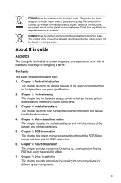
...the crossed out wheeled bin indicates that the product (electrical and electronic equipment) should not be placed in municipal waste. Chapter 5: BIOS information This chapter tells how to perform when installing or removing system components. 3. ix This symbol of the jumpers and internal connectors....describes the general features of the crossed out wheeled bin indicates that you have to change system settings through the BIOS Setup menus and describes the BIOS parameters. 6. DO NOT throw the mercury-containing button cell battery in municipal waste. Chapter 2: Hardware setup ...
...the crossed out wheeled bin indicates that the product (electrical and electronic equipment) should not be placed in municipal waste. Chapter 5: BIOS information This chapter tells how to perform when installing or removing system components. 3. ix This symbol of the jumpers and internal connectors....describes the general features of the crossed out wheeled bin indicates that you have to change system settings through the BIOS Setup menus and describes the BIOS parameters. 6. DO NOT throw the mercury-containing button cell battery in municipal waste. Chapter 2: Hardware setup ...
User Guide
Page 32
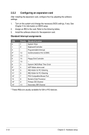
.... 2. See Chapter 5 for information on the system and change the necessary BIOS settings, if any. Refer to the card. Assign an IRQ to the following tables. 3. Programmable Interrupt 4* 12 Communications Port (COM1) 5* 13 -- 6 14 Floppy Disk Controller 7* ...
.... 2. See Chapter 5 for information on the system and change the necessary BIOS settings, if any. Refer to the card. Assign an IRQ to the following tables. 3. Programmable Interrupt 4* 12 Communications Port (COM1) 5* 13 -- 6 14 Floppy Disk Controller 7* ...

User Guide
Page 49
...Output connector (6-1 pin SGPIO1) 6. Clear RTC RAM (CLRTC1) 2. Intel ICH10R® SATA ports...CPU warning LED (ERR_CPU1, ERR_CPU2) Page 4-20 4-20 ASUS RS700D-E6/PS8, RS702D-E6/PS8, RS704D-E6/PS8 4-5 VGA controller setting (3-pin VGA_SW1) 3. A-Type USB4...) 3. LPC debug card connector (14-1 pin LPC1) 5. BMC header (BMC_FW1) 7. System panel connector (20-pin PANEL1) 10. Auxiliary panel connector (20-pin AUX_PANEL1) Page 4-12 4-13 4-14 4-15 4-15 4-16 4-16 4-17 4-18 4-19 Internal LEDs 1. Force BIOS...
...Output connector (6-1 pin SGPIO1) 6. Clear RTC RAM (CLRTC1) 2. Intel ICH10R® SATA ports...CPU warning LED (ERR_CPU1, ERR_CPU2) Page 4-20 4-20 ASUS RS700D-E6/PS8, RS702D-E6/PS8, RS704D-E6/PS8 4-5 VGA controller setting (3-pin VGA_SW1) 3. A-Type USB4...) 3. LPC debug card connector (14-1 pin LPC1) 5. BMC header (BMC_FW1) 7. System panel connector (20-pin PANEL1) 10. Auxiliary panel connector (20-pin AUX_PANEL1) Page 4-12 4-13 4-14 4-15 4-15 4-16 4-16 4-17 4-18 4-19 Internal LEDs 1. Force BIOS...
User Guide
Page 50
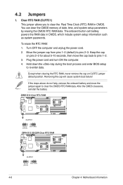
... setup parameters by erasing the CMOS RTC RAM data. Plug the power cord and turn ON the computer. 4. Hold down the key during the boot process and enter BIOS setup to pins 2-3. If the steps ...above do not help, remove the onboard battery and move the cap back to pins 1-2. 3. Except when clearing the RTC RAM, never remove the cap on... about 5-10 seconds, then move the jumper again to clear the Real Time Clock (RTC) RAM in CMOS, which include system setup information such as system passwords. Move the jumper cap from ...
... setup parameters by erasing the CMOS RTC RAM data. Plug the power cord and turn ON the computer. 4. Hold down the key during the boot process and enter BIOS setup to pins 2-3. If the steps ...above do not help, remove the onboard battery and move the cap back to pins 1-2. 3. Except when clearing the RTC RAM, never remove the cap on... about 5-10 seconds, then move the jumper again to clear the Real Time Clock (RTC) RAM in CMOS, which include system setup information such as system passwords. Move the jumper cap from ...
User Guide
Page 52
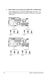
Set to pins 1-2 to select 1.5V BIOS control, pins 2-3 to select 1.2V Force or 3-4 to adjust the DIMM voltage. LVDDR3_SEL2) These jumpers allow you to select 1.35V Force. 4-8 Chapter 4: Motherboard information DDR3 voltage control setting (4-pin LVDDR3_SEL1; 3.
Set to pins 1-2 to select 1.5V BIOS control, pins 2-3 to select 1.2V Force or 3-4 to adjust the DIMM voltage. LVDDR3_SEL2) These jumpers allow you to select 1.35V Force. 4-8 Chapter 4: Motherboard information DDR3 voltage control setting (4-pin LVDDR3_SEL1; 3.

User Guide
Page 55
Set the jumper to pins 1-2. 6. Set the jumper back to pins 2-3. 3. To update the BIOS: 1. Prepare a USB flash disk that contains the original or latest BIOS for the motherboard (XXXXXX.ROM) and the AFUDOS.EXE utility. 2. ASUS RS700D-E6/PS8, RS702D-E6/PS8, RS704D-E6/PS8 4-11 Insert the USB flash and turn on the system. 6. Turn on the system to quickly update or recover the BIOS settings when it becomes corrupted. Shut down the system. 5. Force BIOS recovery setting (3-pin RECOVERY1) This jumper allows you to update the BIOS. 4.
Set the jumper to pins 1-2. 6. Set the jumper back to pins 2-3. 3. To update the BIOS: 1. Prepare a USB flash disk that contains the original or latest BIOS for the motherboard (XXXXXX.ROM) and the AFUDOS.EXE utility. 2. ASUS RS700D-E6/PS8, RS702D-E6/PS8, RS704D-E6/PS8 4-11 Insert the USB flash and turn on the system. 6. Turn on the system to quickly update or recover the BIOS settings when it becomes corrupted. Shut down the system. 5. Force BIOS recovery setting (3-pin RECOVERY1) This jumper allows you to update the BIOS. 4.
User Guide
Page 62
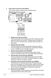
...-mounted system warning speaker. System power LED (3-pin PLED) This 3-pin connector is ON turns the system OFF. 6. The speaker allows you turn on the BIOS settings. System panel connector (20-pin PANEL1) This connector supports several chassis-mounted functions. 1. The message LED is in sleep or soft-off mode depending...
...-mounted system warning speaker. System power LED (3-pin PLED) This 3-pin connector is ON turns the system OFF. 6. The speaker allows you turn on the BIOS settings. System panel connector (20-pin PANEL1) This connector supports several chassis-mounted functions. 1. The message LED is in sleep or soft-off mode depending...

User Guide
Page 65
ASUS RS700D-E6/PS8, RS702D-E6/PS8, RS704D-E6/PS8 Detailed descriptions of the BIOS parameters are also provided. BIOS setup Chapter 5 This chapter tells how to change the system settings through the BIOS Setup menus.
ASUS RS700D-E6/PS8, RS702D-E6/PS8, RS704D-E6/PS8 Detailed descriptions of the BIOS parameters are also provided. BIOS setup Chapter 5 This chapter tells how to change the system settings through the BIOS Setup menus.

User Guide
Page 66
...same as backup when the BIOS fails or gets corrupted during the updating process. Copy the AFUDOS utility (afudos.exe) from the motherboard support CD to the corresponding sections for details on these utilities. ASUS CrashFree BIOS 3 (To recover the BIOS using the AFUDOS utility: ...• Ensure that you can use as shown. 1. Copy the original motherboard BIOS using the AFUDOS utility. 5.1.1 AFUDOS utility The AFUDOS utility allows ...
...same as backup when the BIOS fails or gets corrupted during the updating process. Copy the AFUDOS utility (afudos.exe) from the motherboard support CD to the corresponding sections for details on these utilities. ASUS CrashFree BIOS 3 (To recover the BIOS using the AFUDOS utility: ...• Ensure that you can use as shown. 1. Copy the original motherboard BIOS using the AFUDOS utility. 5.1.1 AFUDOS utility The AFUDOS utility allows ...

User Guide
Page 67
... (9%) DO NOT shut down or reset the system while updating the BIOS to type the exact BIOS filename at the prompt type: afudos /i[filename] where [filename] is completed. Version 1.19(ASUS V2.07(03.11.24BB)) Copyright (C) 2002 American Megatrends, Inc.... BIOS file. A:\>afudos /iRS702DE6.ROM AMI Firmware Update Utility - Reboot the system from the motherboard support CD to the bootable USB flash drive. 3. Erasing flash ...... done Verifying flash .... WARNING!! done Reading flash ...... done Please restart your computer A:\> ASUS RS700D-E6/PS8, RS702D-E6/PS8, RS704D-E6/PS8 ...
... (9%) DO NOT shut down or reset the system while updating the BIOS to type the exact BIOS filename at the prompt type: afudos /i[filename] where [filename] is completed. Version 1.19(ASUS V2.07(03.11.24BB)) Copyright (C) 2002 American Megatrends, Inc.... BIOS file. A:\>afudos /iRS702DE6.ROM AMI Firmware Update Utility - Reboot the system from the motherboard support CD to the bootable USB flash drive. 3. Erasing flash ...... done Verifying flash .... WARNING!! done Reading flash ...... done Please restart your computer A:\> ASUS RS700D-E6/PS8, RS702D-E6/PS8, RS704D-E6/PS8 ...

User Guide
Page 68
... a USB flash drive that contains the BIOS file. If you to enter BIOS Setup to recover BIOS setting. The utility automatically checks the devices for the BIOS file. Recovering the BIOS To recover the BIOS 1. The system requires you want to use the newer BIOS file, download the file at support.asus.com and save it fails or...
... a USB flash drive that contains the BIOS file. If you to enter BIOS Setup to recover BIOS setting. The utility automatically checks the devices for the BIOS file. Recovering the BIOS To recover the BIOS 1. The system requires you want to use the newer BIOS file, download the file at support.asus.com and save it fails or...

User Guide
Page 69
...BIOS settings, load the default settings to download the latest BIOS.... • The default BIOS settings for most conditions to...BIOS Setup program when you are for this program. For example, you can change the power management settings. Do this utility. Select the Load Default Settings item under the Exit Menu. ASUS RS700D-E6/PS8, RS702D-E6/PS8, RS704D-E6/PS8... 5-5 You can also restart by pressing the reset button on your screen. • Visit the ASUS website at www.asus...system using the BIOS Setup program ...BIOS setup program This motherboard ...
...BIOS settings, load the default settings to download the latest BIOS.... • The default BIOS settings for most conditions to...BIOS Setup program when you are for this program. For example, you can change the power management settings. Do this utility. Select the Load Default Settings item under the Exit Menu. ASUS RS700D-E6/PS8, RS702D-E6/PS8, RS704D-E6/PS8... 5-5 You can also restart by pressing the reset button on your screen. • Visit the ASUS website at www.asus...system using the BIOS Setup program ...BIOS setup program This motherboard ...
User Guide
Page 70
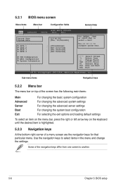
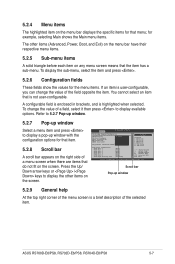
....61 (C)Copyright 1985-2009, American Megatrends, Inc. Some of a menu screen are the navigation keys for that particular menu. 5.2.1 BIOS menu screen Menu items Menu bar Configuration fields General help Main Advanced BIOS SETUP UTILITY Server Boot Exit System Time [13:44:30] System Date [Thu, 01/08/2009] SATA 1 SATA 2 SATA...
....61 (C)Copyright 1985-2009, American Megatrends, Inc. Some of a menu screen are the navigation keys for that particular menu. 5.2.1 BIOS menu screen Menu items Menu bar Configuration fields General help Main Advanced BIOS SETUP UTILITY Server Boot Exit System Time [13:44:30] System Date [Thu, 01/08/2009] SATA 1 SATA 2 SATA...
User Guide
Page 71
... options for that item. 5.2.8 Scroll bar A scroll bar appears on the right side of the selected item. ASUS RS700D-E6/PS8, RS702D-E6/PS8, RS704D-E6/PS8 5-7 To change the value of a field, select it then press to display available options. Advanced BIOS SETUP UTILITY CPU Bridge Chipset Configuration USB Functions [1D2isUaSbBlePdorts] USB Port Configure [82X4USUBSBPoProtrsts] USB 2.0 Controller [E4naUbSlBedP...
... options for that item. 5.2.8 Scroll bar A scroll bar appears on the right side of the selected item. ASUS RS700D-E6/PS8, RS702D-E6/PS8, RS704D-E6/PS8 5-7 To change the value of a field, select it then press to display available options. Advanced BIOS SETUP UTILITY CPU Bridge Chipset Configuration USB Functions [1D2isUaSbBlePdorts] USB Port Configure [82X4USUBSBPoProtrsts] USB 2.0 Controller [E4naUbSlBedP...

User Guide
Page 72
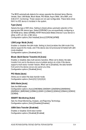
...(C)Copyright 1985-2009, American Megatrends, Inc. 5.3.1 System Time [xx:xx:xx] Allows you to set the system date. 5.3.3 SATA1-4 The BIOS automatically detects the connected IDE devices. Type [Auto] LBA/Large Mode [Auto] Block(Multi-Sector Transfer)M [Auto] PIO Mode [Auto] DMA... Mode [Auto] SMART Monitoring [Auto] 32Bit Data Transfer [Enabled] ←→ Select Screen ↑↓ Select Item +- Main Advanced BIOS SETUP UTILITY Server Boot Exit System Time [13:44:30] System Date [Thu, 01/08/2009] SATA 1 SATA 2 SATA 3 SATA 4 : [ST3160812AS] :...
...(C)Copyright 1985-2009, American Megatrends, Inc. 5.3.1 System Time [xx:xx:xx] Allows you to set the system date. 5.3.3 SATA1-4 The BIOS automatically detects the connected IDE devices. Type [Auto] LBA/Large Mode [Auto] Block(Multi-Sector Transfer)M [Auto] PIO Mode [Auto] DMA... Mode [Auto] SMART Monitoring [Auto] 32Bit Data Transfer [Enabled] ←→ Select Screen ↑↓ Select Item +- Main Advanced BIOS SETUP UTILITY Server Boot Exit System Time [13:44:30] System Date [Thu, 01/08/2009] SATA 1 SATA 2 SATA 3 SATA 4 : [ST3160812AS] :...
User Guide
Page 73
... Block (Multi-Sector Transfer) M [Auto] Enables or disables data multi-sectors transfers. Select [CDROM] if you to the device occurs multiple sectors at a time. The BIOS automatically detects the values opposite the dimmed items (Device, Vendor, Size, LBA Mode, Block Mode, PIO Mode, Async DMA, Ultra DMA, and S.M.A.R.T. These items show.... Type [Auto] Selects the type of the appropriate IDE device type. Configuration options: [Auto] [0] [1] [2] [3] [4] DMA Mode [Auto] Sets the DMA mode. Configuration options: [Disabled] [Enabled] ASUS RS700D-E6/PS8, RS702D-E6/PS8, RS704D-E6/PS8 5-9
... Block (Multi-Sector Transfer) M [Auto] Enables or disables data multi-sectors transfers. Select [CDROM] if you to the device occurs multiple sectors at a time. The BIOS automatically detects the values opposite the dimmed items (Device, Vendor, Size, LBA Mode, Block Mode, PIO Mode, Async DMA, Ultra DMA, and S.M.A.R.T. These items show.... Type [Auto] Selects the type of the appropriate IDE device type. Configuration options: [Auto] [0] [1] [2] [3] [4] DMA Mode [Auto] Sets the DMA mode. Configuration options: [Disabled] [Enabled] ASUS RS700D-E6/PS8, RS702D-E6/PS8, RS704D-E6/PS8 5-9

User Guide
Page 74
...Hard Disk Write Protect [Disabled] Disables or enables device write protection. Configuration options: [0] [5] [10] [15] [20] [25] [30] [35] 5-10 Chapter 5: BIOS setup 5.3.4 IDE Configuration The items in the system. This will be effective only if the device is accessed through... out value for the IDE devices installed in this item to [AHCI]. The AHCI allows the onboard storage driver to configure the item. Main BIOS SETUP UTILITY IDE Configuration SATA Configuration Configure SATA as [Enhanced] [IDE] Hard Disk Write Protect [Disabled] IDE Detect Time Out (Sec) [...
...Hard Disk Write Protect [Disabled] Disables or enables device write protection. Configuration options: [0] [5] [10] [15] [20] [25] [30] [35] 5-10 Chapter 5: BIOS setup 5.3.4 IDE Configuration The items in the system. This will be effective only if the device is accessed through... out value for the IDE devices installed in this item to [AHCI]. The AHCI allows the onboard storage driver to configure the item. Main BIOS SETUP UTILITY IDE Configuration SATA Configuration Configure SATA as [Enhanced] [IDE] Hard Disk Write Protect [Disabled] IDE Detect Time Out (Sec) [...


