User Guide
Page 4
... Chapter 3: Installation options 3.1 Rackmount rail kit items (optional 3-2 3.2 Attaching the rails to the server 3-2 3.3 Attaching the rack rails 3-3 3.4 Rackmounting the server 3-4 Chapter 4: Motherboard information 4.1 Motherboard layouts 4-2 4.2 Jumpers 4-4 4.3 Internal connectors 4-9 Chapter 5: BIOS setup 5.1 Managing and updating your BIOS 5-2 5.1.1 AFUDOS utility 5-2 5.1.2 ASUS CrashFree BIOS 3 utility 5-4 5.2 BIOS setup program 5-5 5.2.1 BIOS menu screen 5-6 5.2.2 Menu bar 5-6 5.2.3 Navigation keys...
... Chapter 3: Installation options 3.1 Rackmount rail kit items (optional 3-2 3.2 Attaching the rails to the server 3-2 3.3 Attaching the rack rails 3-3 3.4 Rackmounting the server 3-4 Chapter 4: Motherboard information 4.1 Motherboard layouts 4-2 4.2 Jumpers 4-4 4.3 Internal connectors 4-9 Chapter 5: BIOS setup 5.1 Managing and updating your BIOS 5-2 5.1.1 AFUDOS utility 5-2 5.1.2 ASUS CrashFree BIOS 3 utility 5-4 5.2 BIOS setup program 5-5 5.2.1 BIOS menu screen 5-6 5.2.2 Menu bar 5-6 5.2.3 Navigation keys...

User Guide
Page 5
... 5-21 5.4.4 USB Configuration 5-21 5.4.5 PCIPnP 5-22 5.4.6 Power On Configuration 5-23 5.4.7 Event Log Configuration 5-24 5.4.8 Hardware Monitor 5-25 5.4.9 ACPI Configuration 5-26 5.4.10 PCI Express Configuration 5-27 5.5 Server menu 5-28 5.6 Boot menu 5-30 5.6.1 Boot Device Priority 5-30 5.6.2 Boot Settings Configuration 5-31 5.6.3 Security 5-32 5.7 Exit menu 5-34 Chapter 6: RAID configuration 6.1 Setting up RAID 6-2 6.1.1 RAID...
... 5-21 5.4.4 USB Configuration 5-21 5.4.5 PCIPnP 5-22 5.4.6 Power On Configuration 5-23 5.4.7 Event Log Configuration 5-24 5.4.8 Hardware Monitor 5-25 5.4.9 ACPI Configuration 5-26 5.4.10 PCI Express Configuration 5-27 5.5 Server menu 5-28 5.6 Boot menu 5-30 5.6.1 Boot Device Priority 5-30 5.6.2 Boot Settings Configuration 5-31 5.6.3 Security 5-32 5.7 Exit menu 5-34 Chapter 6: RAID configuration 6.1 Setting up RAID 6-2 6.1.1 RAID...
User Guide
Page 8
... cable and plug for the devices are unplugged before the signal cables are connected. Dispose of explosion if battery is heavy. This server system is incorrectly replaced. If any additional devices to the manufacturer's instructions. Replace only with a properly grounded electrical outlet to fix... all power cables from connectors, slots, sockets and circuitry. • Avoid dust, humidity, and temperature extremes. Place the server on this server must be conducted by yourself. viii Contact a qualified service technician or your dealer as soon as possible. • To ...
... cable and plug for the devices are unplugged before the signal cables are connected. Dispose of explosion if battery is heavy. This server system is incorrectly replaced. If any additional devices to the manufacturer's instructions. Replace only with a properly grounded electrical outlet to fix... all power cables from connectors, slots, sockets and circuitry. • Avoid dust, humidity, and temperature extremes. Place the server on this server must be conducted by yourself. viii Contact a qualified service technician or your dealer as soon as possible. • To ...
User Guide
Page 9
... are also provided. 7 Chapter 7: Driver installation This chapter provides instructions for installing the necessary drivers for disposal of configuring a server. ix This product has been designed to change system settings through the BIOS Setup menus and describes the BIOS parameters. 6. This... layout, jumper settings, and connector locations. 5. Chapter 5: BIOS information This chapter tells how to enable proper reuse of the server, including sections on front panel and rear panel specifications. 2. This symbol of the crossed out wheeled bin indicates that the product...
... are also provided. 7 Chapter 7: Driver installation This chapter provides instructions for installing the necessary drivers for disposal of configuring a server. ix This product has been designed to change system settings through the BIOS Setup menus and describes the BIOS parameters. 6. This... layout, jumper settings, and connector locations. 5. Chapter 5: BIOS information This chapter tells how to enable proper reuse of the server, including sections on front panel and rear panel specifications. 2. This symbol of the crossed out wheeled bin indicates that the product...

User Guide
Page 10
... worldwide provide updated information for product and software updates. 1. Italics Used to set up and use the proprietary ASUS server management utility. 2. If you complete a task. ASUS Server Web-based Management (ASWM) user guide This manual tells how to emphasize a word or a phrase. Command Example: Means that you perform certain tasks properly, take ...
... worldwide provide updated information for product and software updates. 1. Italics Used to set up and use the proprietary ASUS server management utility. 2. If you complete a task. ASUS Server Web-based Management (ASWM) user guide This manual tells how to emphasize a word or a phrase. Command Example: Means that you perform certain tasks properly, take ...

User Guide
Page 12
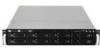
1.1 System package contents Check your system package for the following items. Model Name Chassis RS520-E6/RS8 ASUS R20A 2U Rackmount Chassis Motherboard ASUS Z8NR-D12-SYS Server Board Component 1 x 770W Redundant Power Supply 1 x SATAII/SAS HDD Backplane (BP8LX-R20A) 8 x hot-swap HDD trays (varies by territories) 1 x Front I/O Board (FPB-AR14) 4 x System Fans (...
1.1 System package contents Check your system package for the following items. Model Name Chassis RS520-E6/RS8 ASUS R20A 2U Rackmount Chassis Motherboard ASUS Z8NR-D12-SYS Server Board Component 1 x 770W Redundant Power Supply 1 x SATAII/SAS HDD Backplane (BP8LX-R20A) 8 x hot-swap HDD trays (varies by territories) 1 x Front I/O Board (FPB-AR14) 4 x System Fans (...

User Guide
Page 13
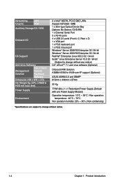
...-swappable 8 x Hot-swap 3.5" SAS/SATA HDD Bays (continued on the next page) ASUS RS520-E6/RS8 1-3 1.3 System specifications The ASUS RS520-E6/RS8 is a server featuring the ASUS Z8NR-D12-SYS server board. Supports software RAID 0, 1 & 10 Optional: ASUS PIKE 1068E 8-port SAS RAID card - Supports software RAID 0, 1 & 1E ASUS PIKE 1078 8-port SAS RAID card - Supports hardware RAID 0, 1, 10, 5 & 6 HDD...
...-swappable 8 x Hot-swap 3.5" SAS/SATA HDD Bays (continued on the next page) ASUS RS520-E6/RS8 1-3 1.3 System specifications The ASUS RS520-E6/RS8 is a server featuring the ASUS Z8NR-D12-SYS server board. Supports software RAID 0, 1 & 10 Optional: ASUS PIKE 1068E 8-port SAS RAID card - Supports software RAID 0, 1 & 1E ASUS PIKE 1078 8-port SAS RAID card - Supports hardware RAID 0, 1, 10, 5 & 6 HDD...
User Guide
Page 14
... x External Serial Port 3 x RJ-45 ports 4 x USB 2.0 ports (Front x 2, Rear x 2) 1 x VGA port 1 x PS/2 keyboard port 1 x PS/2 mouse port Windows® Server 2008 R2 Enterprise 32 / 64-bit Windows® Server 2003 R2 Enterprise 32 / 64-bit RedHat® Enterprise Linux AS5.0 32 / 64-bit SuSE® Linux Enterprise... Server 10.0 32 / 64-bit (Subject to change without any notice) CA® eTrust™ 7.1 anti-virus software (Optional) Onboard IPMI Solution ASMB4-iKVM for KVM-over-IP support (Optional) ASUS ASWM 2.0 and SNMP® 615mm x 444mm x 87mm...
... x External Serial Port 3 x RJ-45 ports 4 x USB 2.0 ports (Front x 2, Rear x 2) 1 x VGA port 1 x PS/2 keyboard port 1 x PS/2 mouse port Windows® Server 2008 R2 Enterprise 32 / 64-bit Windows® Server 2003 R2 Enterprise 32 / 64-bit RedHat® Enterprise Linux AS5.0 32 / 64-bit SuSE® Linux Enterprise... Server 10.0 32 / 64-bit (Subject to change without any notice) CA® eTrust™ 7.1 anti-virus software (Optional) Onboard IPMI Solution ASMB4-iKVM for KVM-over-IP support (Optional) ASUS ASWM 2.0 and SNMP® 615mm x 444mm x 87mm...

User Guide
Page 15
1.4 Front panel features The barebone server displays a simple yet stylish front panel with openings for the rear panel connectors on the motherboard. 3 Expansion slots ...; The ports for the PS/2 keyboard, PS/2 mouse, USB, VGA, and Gigabit LAN do not appear on the front panel. ASUS RS520-E6/RS8 1-5 The power and reset buttons, LED indicators, optical drive, and two USB ports are located on the rear panel if motherboard... The rear panel includes the expansion slots, system power socket, and rear fans. Refer to section 1.7.1 Front panel LEDs for ASUS ASMB4-iKVM controller card only.
1.4 Front panel features The barebone server displays a simple yet stylish front panel with openings for the rear panel connectors on the motherboard. 3 Expansion slots ...; The ports for the PS/2 keyboard, PS/2 mouse, USB, VGA, and Gigabit LAN do not appear on the front panel. ASUS RS520-E6/RS8 1-5 The power and reset buttons, LED indicators, optical drive, and two USB ports are located on the rear panel if motherboard... The rear panel includes the expansion slots, system power socket, and rear fans. Refer to section 1.7.1 Front panel LEDs for ASUS ASMB4-iKVM controller card only.
User Guide
Page 16
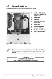
.... *WARNING HAZARDOUS MOVING PARTS KEEP FINGERS AND OTHER BODY PARTS AWAY 1-6 Chapter 1: Product introduction ASUS Z8NR-D12-SYS server board 5. SATA/SAS backplane 7. Front I/O board (hidden) 6 7 8 9 The barebone server does not include a floppy disk drive. 1.6 Internal features The barebone server includes the basic components as shown. 1. 2 x PCI-E x8 slot (at x8 link)+ PCI-E x4...
.... *WARNING HAZARDOUS MOVING PARTS KEEP FINGERS AND OTHER BODY PARTS AWAY 1-6 Chapter 1: Product introduction ASUS Z8NR-D12-SYS server board 5. SATA/SAS backplane 7. Front I/O board (hidden) 6 7 8 9 The barebone server does not include a floppy disk drive. 1.6 Internal features The barebone server includes the basic components as shown. 1. 2 x PCI-E x8 slot (at x8 link)+ PCI-E x4...

User Guide
Page 40
2.8.5 Installing ASMB4 series management board (optional) Follow the steps below to the LAN port 3 (dedicated LAN) or LAN port 1 (shared LAN) for server management. 2-22 LAN port 3 LAN port 1 Chapter 2: Hardware setup Insert the LAN cable plug to install an optional ASMB4 series management board on the BMC ...
2.8.5 Installing ASMB4 series management board (optional) Follow the steps below to the LAN port 3 (dedicated LAN) or LAN port 1 (shared LAN) for server management. 2-22 LAN port 3 LAN port 1 Chapter 2: Hardware setup Insert the LAN cable plug to install an optional ASMB4 series management board on the BMC ...

User Guide
Page 41
Installation options Chapter 3 This chapter describes how to install the optional components and devices into the barebone server. ASUS RS520-E6/RS8 2-
Installation options Chapter 3 This chapter describes how to install the optional components and devices into the barebone server. ASUS RS520-E6/RS8 2-

User Guide
Page 42
... front panel until it locks in place. 2. Secure the front end of the server rail to the server To attach the server rails: 1. 3.1 Rackmount rail kit items (optional) Your rackmount rail kit package contains: • two pair of server rails (for the server) • two pairs of rack rails (for the rack) • Nut-and... Front end Rack rails 3.2 Attaching the rails to the side of the chassis with one screw. 3-2 Chapter 3: Installation options Attach the front end of the server rail to the side of the chassis, matching each of the five hooks to the holes on the rail.
... front panel until it locks in place. 2. Secure the front end of the server rail to the server To attach the server rails: 1. 3.1 Rackmount rail kit items (optional) Your rackmount rail kit package contains: • two pair of server rails (for the server) • two pairs of rack rails (for the rack) • Nut-and... Front end Rack rails 3.2 Attaching the rails to the side of the chassis with one screw. 3-2 Chapter 3: Installation options Attach the front end of the server rail to the side of the chassis, matching each of the five hooks to the holes on the rail.

User Guide
Page 43
... the depth of the rack to the side of the rail with two rack screws. 9. Ensure that it locks in place. 4. ASUS RS520-E6/RS8 3-3 Secure the rear end of the server rail to determine the length of the rack space. 7. Secure the rear end of the chassis with two rack screws. 8. Repeat steps... 1 to 4 to attach the second server rail to the front of the rack rails. 5. Measure the rack rail when assembled to ensure that the front end of the rack rail goes...
... the depth of the rack to the side of the rail with two rack screws. 9. Ensure that it locks in place. 4. ASUS RS520-E6/RS8 3-3 Secure the rear end of the server rail to determine the length of the rack space. 7. Secure the rear end of the chassis with two rack screws. 8. Repeat steps... 1 to 4 to attach the second server rail to the front of the rack rails. 5. Measure the rack rail when assembled to ensure that the front end of the rack rail goes...

User Guide
Page 44
Drive two screws on the mounting ears. 2. To uninstall the server from the rack. Remove the screws secured on both sides to secure the server in place. Remember to press the latches on both mounting ears to release the server from the rack. 3-4 Chapter 3: Installation options Hold the mounting ears, then pull the server from the rack: 1. Align the server rails with the rack rails, then push the server all the way to the rack: 1. 3.4 Rackmounting the server To mount the server to the depth of the rack. 2.
Drive two screws on the mounting ears. 2. To uninstall the server from the rack. Remove the screws secured on both sides to secure the server in place. Remember to press the latches on both mounting ears to release the server from the rack. 3-4 Chapter 3: Installation options Hold the mounting ears, then pull the server from the rack: 1. Align the server rails with the rack rails, then push the server all the way to the rack: 1. 3.4 Rackmounting the server To mount the server to the depth of the rack. 2.

User Guide
Page 66
... of the screen has the following main items: Main Advanced Server Boot Exit For changing the basic system configuration For changing the advanced system settings For changing the advanced server settings For changing the system boot configuration For selecting the exit... Exit v02.61 (C)Copyright 1985-2008, American Megatrends, Inc. 5.2.1 BIOS menu screen Menu items Menu bar Configuration fields General help Main Advanced BIOS SETUP UTILITY Server Boot Exit System Time [13:44:30] System Date [Tue, 11/04/2008] Legacy Diskette A [1.44M, 3.5 in.] SATA 1 SATA 2 SATA 3 ...
... of the screen has the following main items: Main Advanced Server Boot Exit For changing the basic system configuration For changing the advanced system settings For changing the advanced server settings For changing the system boot configuration For selecting the exit... Exit v02.61 (C)Copyright 1985-2008, American Megatrends, Inc. 5.2.1 BIOS menu screen Menu items Menu bar Configuration fields General help Main Advanced BIOS SETUP UTILITY Server Boot Exit System Time [13:44:30] System Date [Tue, 11/04/2008] Legacy Diskette A [1.44M, 3.5 in.] SATA 1 SATA 2 SATA 3 ...

User Guide
Page 68
Main Advanced BIOS SETUP UTILITY Server Boot Exit System Time [13:44:30] System Date [Tue, 11/04/2008] Legacy Diskette A [Disabled] SATA 1 SATA 2 SATA 3 SATA 4 SATA 5 SATA 6 : [ST3160812AS] : [Not Detected] : [... menu screen for information on the menu screen items and how to select a field. Configuration options: [Disabled] [360 KB, 5.25 in.] [1.2 MB, 5.25 in.] [720 KB, 3.5 in.] [1.44 MB, 3.5 in] [2.88 MB, 3.5 in] 5-8 Chapter 5: BIOS setup Use [+] or [-] to configure system Date. ←→ Select Screen ↑↓ Select Item Enter Go to...
Main Advanced BIOS SETUP UTILITY Server Boot Exit System Time [13:44:30] System Date [Tue, 11/04/2008] Legacy Diskette A [Disabled] SATA 1 SATA 2 SATA 3 SATA 4 SATA 5 SATA 6 : [ST3160812AS] : [Not Detected] : [... menu screen for information on the menu screen items and how to select a field. Configuration options: [Disabled] [360 KB, 5.25 in.] [1.2 MB, 5.25 in.] [720 KB, 3.5 in.] [1.44 MB, 3.5 in] [2.88 MB, 3.5 in] 5-8 Chapter 5: BIOS setup Use [+] or [-] to configure system Date. ←→ Select Screen ↑↓ Select Item Enter Go to...
User Guide
Page 74
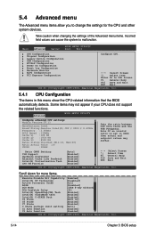
Main Advanced Server BIOS SETUP UTILITY Boot Exit CPU Configuration Chipset Configuration Legacy Device Configuration USB Configuration PCIPnP Configuration Power On Configuration Event Log Configuration Hardware Monitor ACPI ...
Main Advanced Server BIOS SETUP UTILITY Boot Exit CPU Configuration Chipset Configuration Legacy Device Configuration USB Configuration PCIPnP Configuration Power On Configuration Event Log Configuration Hardware Monitor ACPI ...

User Guide
Page 88
...] [VT-UTF8] Remote Access [Enabled] Enables or disables the remote access feature. Configuration options: [COM1] [COM2] Base Address. Main Advanced Server BIOS SETUP UTILITY Boot Exit Remote Access Configuration Configure Remote Access. ←→ Select Screen ↑↓ Select Item Enter Go to display the..., 3] This item is set to [Enabled]. Serial port number [COM2] Selects the serial port for console redirection. 5.5 Server menu The Server menu items allow you to configure the Remote Access features. Select an item then press to Sub Screen F1 General Help F10...
...] [VT-UTF8] Remote Access [Enabled] Enables or disables the remote access feature. Configuration options: [COM1] [COM2] Base Address. Main Advanced Server BIOS SETUP UTILITY Boot Exit Remote Access Configuration Configure Remote Access. ←→ Select Screen ↑↓ Select Item Enter Go to display the..., 3] This item is set to [Enabled]. Serial port number [COM2] Selects the serial port for console redirection. 5.5 Server menu The Server menu items allow you to configure the Remote Access features. Select an item then press to Sub Screen F1 General Help F10...

User Guide
Page 90
... Device [XXXXXXX] These items specify the boot device priority sequence from the available devices. Configuration options: [xxxxx Drive] [Disabled] 5-30 Chapter 5: BIOS setup Main Advanced Server BIOS SETUP UTILITY Boot Exit Boot Settings Boot Device Priority Boot Settings Configuration Security Specifies the Boot Device Priority sequence. A virtual floppy disk drive (Floppy...
... Device [XXXXXXX] These items specify the boot device priority sequence from the available devices. Configuration options: [xxxxx Drive] [Disabled] 5-30 Chapter 5: BIOS setup Main Advanced Server BIOS SETUP UTILITY Boot Exit Boot Settings Boot Device Priority Boot Settings Configuration Security Specifies the Boot Device Priority sequence. A virtual floppy disk drive (Floppy...