User Guide
Page 11
ASUS RS500A-E6/PS4 1- It includes sections on front panel and rear panel specifications. Product introduction Chapter 1 This chapter describes the general features of the chassis kit.
ASUS RS500A-E6/PS4 1- It includes sections on front panel and rear panel specifications. Product introduction Chapter 1 This chapter describes the general features of the chassis kit.
User Guide
Page 13
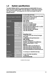
... supports AMD® LGA 1944 Opteron™ 6100 series processors with HyperTransport™ technology, plus other latest technologies through the chipsets onboard. 1.3 System specifications The ASUS RS500A-E6/PS4 is a server featuring the ASUS KGNE-D16 server board.
... supports AMD® LGA 1944 Opteron™ 6100 series processors with HyperTransport™ technology, plus other latest technologies through the chipsets onboard. 1.3 System specifications The ASUS RS500A-E6/PS4 is a server featuring the ASUS KGNE-D16 server board.
User Guide
Page 15
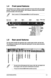
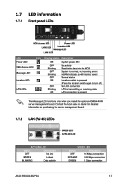
... expansion slots, system power socket, and rear fans. 1.4 Front panel features The barebone server displays a simple yet stylish front panel with openings for ASUS ASMB4-iKVM controller card only. ASUS RS500A-E6/PS4 1-5 The power and reset buttons, LED indicators, optical drive, and two USB ports are located on the motherboard. Refer to section 1.7.1 Front...
... expansion slots, system power socket, and rear fans. 1.4 Front panel features The barebone server displays a simple yet stylish front panel with openings for ASUS ASMB4-iKVM controller card only. ASUS RS500A-E6/PS4 1-5 The power and reset buttons, LED indicators, optical drive, and two USB ports are located on the motherboard. Refer to section 1.7.1 Front...
User Guide
Page 17
... Status Description OFF No link GREEN Linked BLINKING Data activity SPEED LED Status Description OFF 10 Mbps connection ORANGE 100 Mbps connection GREEN 1 Gbps connection ASUS RS500A-E6/PS4 1-7 no incoming event ASWM indicates a HW monitor event Normal status Location switch is pressed (Press the location switch again to turn off) No LAN connection...
... Status Description OFF No link GREEN Linked BLINKING Data activity SPEED LED Status Description OFF 10 Mbps connection ORANGE 100 Mbps connection GREEN 1 Gbps connection ASUS RS500A-E6/PS4 1-7 no incoming event ASWM indicates a HW monitor event Normal status Location switch is pressed (Press the location switch again to turn off) No LAN connection...
User Guide
Page 19
Hardware setup Chapter 2 This chapter lists the hardware setup procedures that you have to perform when installing or removing system components. ASUS RS500A-E6/PS4 2-
Hardware setup Chapter 2 This chapter lists the hardware setup procedures that you have to perform when installing or removing system components. ASUS RS500A-E6/PS4 2-
User Guide
Page 21
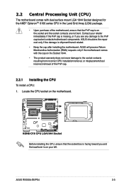
Contact your left. ASUS will process Return Merchandise Authorization (RMA) requests only if the motherboard comes with dual surface mount LGA 1944 Socket designed for the AMD® Opteron&#... to the socket contacts resulting from incorrect CPU installation/removal, or misplacement/loss/ incorrect removal of the PnP cap. 2.2.1 Installing the CPU To install a CPU: 1. ASUS RS500A-E6/PS4 2-3 ASUS shoulders the repair cost only if the damage is missing, or if you and the load lever is on the socket and the socket contacts...
Contact your left. ASUS will process Return Merchandise Authorization (RMA) requests only if the motherboard comes with dual surface mount LGA 1944 Socket designed for the AMD® Opteron&#... to the socket contacts resulting from incorrect CPU installation/removal, or misplacement/loss/ incorrect removal of the PnP cap. 2.2.1 Installing the CPU To install a CPU: 1. ASUS RS500A-E6/PS4 2-3 ASUS shoulders the repair cost only if the damage is missing, or if you and the load lever is on the socket and the socket contacts...
User Guide
Page 23
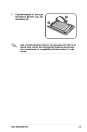
Some heatsinks come with , ensuring that it snaps into A the retention tab. ASUS RS500A-E6/PS4 2-5 7. If so, skip this step. B Apply some Thermal Interface Material to the exposed area of the CPU that the heatsink will be in an even thin layer. Close the load plate (A), then push the load lever (B) until it is spread in contact with pre-applied Thermal Interface Material.
Some heatsinks come with , ensuring that it snaps into A the retention tab. ASUS RS500A-E6/PS4 2-5 7. If so, skip this step. B Apply some Thermal Interface Material to the exposed area of the CPU that the heatsink will be in an even thin layer. Close the load plate (A), then push the load lever (B) until it is spread in contact with pre-applied Thermal Interface Material.
User Guide
Page 25
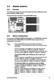
.../4GB Unbuffered with ECC/Non-ECC DDR3 DIMMs into the DIMM sockets using the memory configurations in the order as follows: DIMM_A2 -> DIMM_C2 -> DIMM_B2 -> DIMM_D2. ASUS RS500A-E6/PS4 2-7 For CPU1 + CPU2 configuration, install DIMMs in this section. • Always install DIMMs with sixteen (16) Double Data Rate 3 (DDR3) Dual Inline Memory Modules (DIMM...
.../4GB Unbuffered with ECC/Non-ECC DDR3 DIMMs into the DIMM sockets using the memory configurations in the order as follows: DIMM_A2 -> DIMM_C2 -> DIMM_B2 -> DIMM_D2. ASUS RS500A-E6/PS4 2-7 For CPU1 + CPU2 configuration, install DIMMs in this section. • Always install DIMMs with sixteen (16) Double Data Rate 3 (DDR3) Dual Inline Memory Modules (DIMM...
User Guide
Page 27
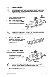
... clips outward. 2. Remove the DIMM from the socket. DO NOT force a DIMM into the socket until the retaining clips snap 3 back in only one direction. ASUS RS500A-E6/PS4 2-9 Failure to do so may cause severe damage to unlock the DIMM. 1 1 DIMM notch Support the DIMM lightly with your fingers when pressing the retaining...
... clips outward. 2. Remove the DIMM from the socket. DO NOT force a DIMM into the socket until the retaining clips snap 3 back in only one direction. ASUS RS500A-E6/PS4 2-9 Failure to do so may cause severe damage to unlock the DIMM. 1 1 DIMM notch Support the DIMM lightly with your fingers when pressing the retaining...
User Guide
Page 29
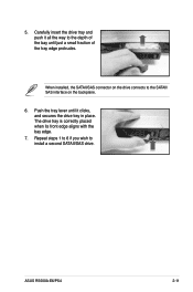
Repeat steps 1 to 6 if you wish to the depth of the tray edge protrudes. Carefully insert the drive tray and push it clicks, and secures the drive tray in place. Push the tray lever until just a small fraction of the bay until it all the way to install a second SATAII/SAS drive. ASUS RS500A-E6/PS4 2-11 When installed, the SATAII/SAS connector on the drive connects to the SATAII/ SAS interface on the backplane. 6. The drive tray is correctly placed when its front edge aligns with the bay edge. 7. 5.
Repeat steps 1 to 6 if you wish to the depth of the tray edge protrudes. Carefully insert the drive tray and push it clicks, and secures the drive tray in place. Push the tray lever until just a small fraction of the bay until it all the way to install a second SATAII/SAS drive. ASUS RS500A-E6/PS4 2-11 When installed, the SATAII/SAS connector on the drive connects to the SATAII/ SAS interface on the backplane. 6. The drive tray is correctly placed when its front edge aligns with the bay edge. 7. 5.
User Guide
Page 31
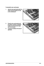
ASUS RS500A-E6/PS4 2-13 To reinstall the riser card bracket: 1. Align the riser card bracket with the rear panel. 3. Connect the cable(s) to the PCI Express x16 slot on the motherboard. 2. Press the riser card bracket until the golden connectors completely fit the slot and the bracket aligns with the cards to the card, if applicable.
ASUS RS500A-E6/PS4 2-13 To reinstall the riser card bracket: 1. Align the riser card bracket with the rear panel. 3. Connect the cable(s) to the PCI Express x16 slot on the motherboard. 2. Press the riser card bracket until the golden connectors completely fit the slot and the bracket aligns with the cards to the card, if applicable.
User Guide
Page 33
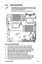
... to motherboard) 3. USB connector (from power supply to front I/O board) 6. Auxiliary panel connector (from motherboard to front I /O board) 7. Panel connector (from motherboard to front I /O board) ASUS RS500A-E6/PS4 2-15 SATA connectors (from motherboard CPU_FAN2, FRNT_FAN1, FRNT_FAN2, FRNT_FAN3, and FRNT_FAN4 to SATAII/SAS backplane board) 8. System fan connectors (from motherboard to system fans) 5. SAS...
... to motherboard) 3. USB connector (from power supply to front I/O board) 6. Auxiliary panel connector (from motherboard to front I /O board) 7. Panel connector (from motherboard to front I /O board) ASUS RS500A-E6/PS4 2-15 SATA connectors (from motherboard CPU_FAN2, FRNT_FAN1, FRNT_FAN2, FRNT_FAN3, and FRNT_FAN4 to SATAII/SAS backplane board) 8. System fan connectors (from motherboard to system fans) 5. SAS...
User Guide
Page 35
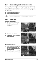
... fan, then set aside. 3. Repeat steps 1 to 2 to the fan cage. The airflow directional arrow on the motherboard. 2. ASUS RS500A-E6/PS4 2-17 Or you may need to install the optional components into the system. ASUS ASMB4-iKVM (optional) Ensure that the system is turned off before removing any components. 2.8.1 System fans To uninstall the...
... fan, then set aside. 3. Repeat steps 1 to 2 to the fan cage. The airflow directional arrow on the motherboard. 2. ASUS RS500A-E6/PS4 2-17 Or you may need to install the optional components into the system. ASUS ASMB4-iKVM (optional) Ensure that the system is turned off before removing any components. 2.8.1 System fans To uninstall the...
User Guide
Page 37
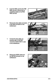
Remove the SGPIO cable from the SGPIO3 connector on the PIKE RAID card slot. 6. Connect the data cables, by numerial order, to the SATA connectors on the motherboard. 8. 5. Remove the data cables connected to the SAS connectors labeled SAS1-4 (red) on the motherboard. 7. Insert the RAID card into the PIKE RAID card slot. ASUS RS500A-E6/PS4 2-19 Ensure that it is completely seated on the motherboard.
Remove the SGPIO cable from the SGPIO3 connector on the PIKE RAID card slot. 6. Connect the data cables, by numerial order, to the SATA connectors on the motherboard. 8. 5. Remove the data cables connected to the SAS connectors labeled SAS1-4 (red) on the motherboard. 7. Insert the RAID card into the PIKE RAID card slot. ASUS RS500A-E6/PS4 2-19 Ensure that it is completely seated on the motherboard.
User Guide
Page 39
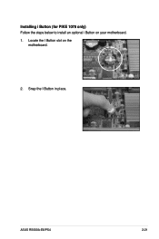
Snap the I Button slot on your motherboard. 1. ASUS RS500A-E6/PS4 2-21 Installing i Button (for PIKE 1078 only) Follow the steps below to install an optional i Button on the motherboard. 2. Locate the I Button in place.
Snap the I Button slot on your motherboard. 1. ASUS RS500A-E6/PS4 2-21 Installing i Button (for PIKE 1078 only) Follow the steps below to install an optional i Button on the motherboard. 2. Locate the I Button in place.
User Guide
Page 41
Installation options Chapter 3 This chapter describes how to install the optional components and devices into the barebone server. ASUS RS500A-E6/PS4 2-
Installation options Chapter 3 This chapter describes how to install the optional components and devices into the barebone server. ASUS RS500A-E6/PS4 2-
User Guide
Page 43
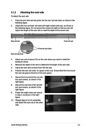
... the rack to meet the depth of the rack rails. 5. Position the rack rail to assemble and attach the rack rail on the other 8 side. 9 8 9 7 ASUS RS500A-E6/PS4 3-3 Attach the front and rear rail racks with two rack screws, as shown in the right figure. 10. Fasten the eight screw you want to...
... the rack to meet the depth of the rack rails. 5. Position the rack rail to assemble and attach the rack rail on the other 8 side. 9 8 9 7 ASUS RS500A-E6/PS4 3-3 Attach the front and rear rail racks with two rack screws, as shown in the right figure. 10. Fasten the eight screw you want to...
User Guide
Page 45
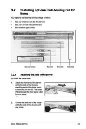
ASUS RS500A-E6/PS4 3-5 Then slide the rail toward the front panel until it locks in place. 2. Secure the front end of the server rail to the server To ...
ASUS RS500A-E6/PS4 3-5 Then slide the rail toward the front panel until it locks in place. 2. Secure the front end of the server rail to the server To ...
User Guide
Page 47
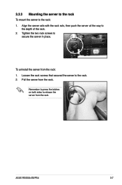
ASUS RS500A-E6/PS4 3-7 Loosen the rack screws that secured the server to release the server from the rack. Pull the server from the rack: 1. Remember to press the latches on both sides to the rack. 2. 3.2.3 Mounting the server to the rack To mount the server to the depth of the rack. 2. To uninstall the server from the rack. Align the server rails with the rack rails, then push the server all the way to the rack: 1. Tighten the two rack screws to secure the server in place.
ASUS RS500A-E6/PS4 3-7 Loosen the rack screws that secured the server to release the server from the rack. Pull the server from the rack: 1. Remember to press the latches on both sides to the rack. 2. 3.2.3 Mounting the server to the rack To mount the server to the depth of the rack. 2. To uninstall the server from the rack. Align the server rails with the rack rails, then push the server all the way to the rack: 1. Tighten the two rack screws to secure the server in place.

User Guide
Page 49
Motherboard info Chapter 4 This chapter includes the motherboard layout, and brief descriptions of the jumpers and internal connectors. ASUS RS500A-E6/PS4 3- 4-1
Motherboard info Chapter 4 This chapter includes the motherboard layout, and brief descriptions of the jumpers and internal connectors. ASUS RS500A-E6/PS4 3- 4-1


