
User Guide
Page 13
1.2 Serial number label For faster and quicker troubleshooting solutions from the ASUS Technical Support team, provide the product's serial number containing 12 characters such as xxS2xxxxxxxx as shown in the figure below. RS320Q-E7/RS12 xxS0xxxxxxxxxx ASUS RS320Q-E7/RS12 1-3
1.2 Serial number label For faster and quicker troubleshooting solutions from the ASUS Technical Support team, provide the product's serial number containing 12 characters such as xxS2xxxxxxxx as shown in the figure below. RS320Q-E7/RS12 xxS0xxxxxxxxxx ASUS RS320Q-E7/RS12 1-3

User Guide
Page 15
Model Name Graphic VGA RS320Q-E7/RS12 Aspeed AST2050 + 16MB VRAM Per Node: Onboard I/O Connectors OS Support Out of Band Management Remote Solution Hardware Software Dimension (HH x WW x DD) Net Weight Kg (... (Optional) ASUS ASWM Enterprise 750mm x 444mm x 87mm (2U) 25 Kg 1+1 Redundant 920W 80PLUS Platinum Power Supply 920W: 100-240Vac, 11-4.4A, 50-60Hz Class I Operating temperature: 10°C-35°C Non-operating temperature: -40°C-70°C Non-operating humidity: 20%-90% ( Non-condensing) Specifications are subject to change without notice. ASUS RS320Q-E7/RS12 1-5
Model Name Graphic VGA RS320Q-E7/RS12 Aspeed AST2050 + 16MB VRAM Per Node: Onboard I/O Connectors OS Support Out of Band Management Remote Solution Hardware Software Dimension (HH x WW x DD) Net Weight Kg (... (Optional) ASUS ASWM Enterprise 750mm x 444mm x 87mm (2U) 25 Kg 1+1 Redundant 920W 80PLUS Platinum Power Supply 920W: 100-240Vac, 11-4.4A, 50-60Hz Class I Operating temperature: 10°C-35°C Non-operating temperature: -40°C-70°C Non-operating humidity: 20%-90% ( Non-condensing) Specifications are subject to change without notice. ASUS RS320Q-E7/RS12 1-5

User Guide
Page 17
LAN port 2 LAN port 3* LAN port 1 VGA port Serial port USB ports * This port is for ASUS ASMB5-iKVM controller card only. 1.6 Internal features 6 4 6 5 3 1 2 ASUS RS320Q-E7/RS12 1-7
LAN port 2 LAN port 3* LAN port 1 VGA port Serial port USB ports * This port is for ASUS ASMB5-iKVM controller card only. 1.6 Internal features 6 4 6 5 3 1 2 ASUS RS320Q-E7/RS12 1-7

User Guide
Page 19
... ON System power ON OFF System is turned on. OFF No LAN connection Blinking LAN is transmitting or receiving data ON LAN connection is present ASUS RS320Q-E7/RS12 1-9 Press the location button again to turn off. Without ASMB5-iKVM installed: CPU over-heated ON 2. no incoming event 1.
... ON System power ON OFF System is turned on. OFF No LAN connection Blinking LAN is transmitting or receiving data ON LAN connection is present ASUS RS320Q-E7/RS12 1-9 Press the location button again to turn off. Without ASMB5-iKVM installed: CPU over-heated ON 2. no incoming event 1.

User Guide
Page 23
Hold the server node lever and press the node latch. 3. Removing the server node 1. When installing only two nodes, install the nodes to section 1.5 Rear panel features for details. Remove the screw located on the node latch. 2. ASUS RS320Q-E7/RS12 2-3 Firmly pull the server node out of the server chassis. Refer to node slot number 1 and 3 or number 2 and 4.
Hold the server node lever and press the node latch. 3. Removing the server node 1. When installing only two nodes, install the nodes to section 1.5 Rear panel features for details. Remove the screw located on the node latch. 2. ASUS RS320Q-E7/RS12 2-3 Firmly pull the server node out of the server chassis. Refer to node slot number 1 and 3 or number 2 and 4.

User Guide
Page 25
PnP cap Cap tab ASUS RS320Q-E7/RS12 2-5 2. Load lever A B Retention tab Load plate 4. To prevent damage to remove the PnP cap from the retention tab. Lift the load lever in the direction of the arrow until it to the right (B) until the load plate is released from the CPU socket. Press the load lever with your thumb (A), and then move it is completely lifted. Lift the tab only to the socket pins, do not remove the PnP cap unless you are installing a CPU. 3.
PnP cap Cap tab ASUS RS320Q-E7/RS12 2-5 2. Load lever A B Retention tab Load plate 4. To prevent damage to remove the PnP cap from the retention tab. Lift the load lever in the direction of the arrow until it to the right (B) until the load plate is released from the CPU socket. Press the load lever with your thumb (A), and then move it is completely lifted. Lift the tab only to the socket pins, do not remove the PnP cap unless you are installing a CPU. 3.

User Guide
Page 27
Insert the load lever under the retention tab. ASUS RS320Q-E7/RS12 2-7 8.
Insert the load lever under the retention tab. ASUS RS320Q-E7/RS12 2-7 8.

User Guide
Page 29
... DDR3 DIMMs into the DIMM sockets using the memory configurations in slots A2 and B2 (orange). • Always install DIMMs with the same CAS latency. ASUS RS320Q-E7/RS12 2-9 2.3 System memory 2.3.1 Overview The motherboard comes with the retailer to ASUS Server AVL for latest update. • Start installing the DIMMs in this section.
... DDR3 DIMMs into the DIMM sockets using the memory configurations in slots A2 and B2 (orange). • Always install DIMMs with the same CAS latency. ASUS RS320Q-E7/RS12 2-9 2.3 System memory 2.3.1 Overview The motherboard comes with the retailer to ASUS Server AVL for latest update. • Start installing the DIMMs in this section.

User Guide
Page 31
.... 3. The drive tray ejects slightly after you pull out the lever. Use two screws on the tray, then secure it with four screws. spring lock 2. ASUS RS320Q-E7/RS12 2-11 Push the spring lock to the right, then pull the tray lever outward to fit different types of the drive tray holes. 2.4 Hard disk... drives The system supports three hot-swap SATAII/SAS hard disk drives per node (available only when an optional ASUS PIKE SAS RAID card is installed) or three hot-swap SATAII hard disk drives per node. To install a hot-swap SATAII/SAS HDD: 1.
.... 3. The drive tray ejects slightly after you pull out the lever. Use two screws on the tray, then secure it with four screws. spring lock 2. ASUS RS320Q-E7/RS12 2-11 Push the spring lock to the right, then pull the tray lever outward to fit different types of the drive tray holes. 2.4 Hard disk... drives The system supports three hot-swap SATAII/SAS hard disk drives per node (available only when an optional ASUS PIKE SAS RAID card is installed) or three hot-swap SATAII hard disk drives per node. To install a hot-swap SATAII/SAS HDD: 1.

User Guide
Page 33
... hold the riser card bracket, and then pull it up to the riser card bracket The barebone server comes with a screw. PCI Express x16 slot ASUS RS320Q-E7/RS12 2-13 Install a PCI Express x16 card to install PCI Express x16 expansion cards. To install a PCI Express x16 card: 1. Place the riser card bracket on...
... hold the riser card bracket, and then pull it up to the riser card bracket The barebone server comes with a screw. PCI Express x16 slot ASUS RS320Q-E7/RS12 2-13 Install a PCI Express x16 card to install PCI Express x16 expansion cards. To install a PCI Express x16 card: 1. Place the riser card bracket on...

User Guide
Page 35
... to SATAII/SAS connection board) 5. Panel connector (from connection board to Chapter 4 for detailed information on the connectors. SATA connectors (from motherboard to connection board) ASUS RS320Q-E7/RS12 2-15 Auxiliary panel connector (from motherboard to connection board) 4. System fan connectors (FRNT_FAN1, FRNT_FAN2, FRNT_FAN3 and FRNT_FAN4) 3. 2.6 Cable connections • The bundled system cables are...
... to SATAII/SAS connection board) 5. Panel connector (from connection board to Chapter 4 for detailed information on the connectors. SATA connectors (from motherboard to connection board) ASUS RS320Q-E7/RS12 2-15 Auxiliary panel connector (from motherboard to connection board) 4. System fan connectors (FRNT_FAN1, FRNT_FAN2, FRNT_FAN3 and FRNT_FAN4) 3. 2.6 Cable connections • The bundled system cables are...
User Guide
Page 37
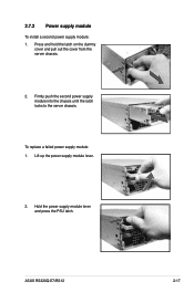
2.7.2 Power supply module To install a second power supply module: 1. Lift up the power supply module lever. 2. Hold the power supply module lever and press the PSU latch. To replace a failed power supply module: 1. Press and hold the latch on the dummy cover and pull out the cover from the server chassis. 2. ASUS RS320Q-E7/RS12 2-17 Firmly push the second power supply module into the chassis until the latch locks to the server chassis.
2.7.2 Power supply module To install a second power supply module: 1. Lift up the power supply module lever. 2. Hold the power supply module lever and press the PSU latch. To replace a failed power supply module: 1. Press and hold the latch on the dummy cover and pull out the cover from the server chassis. 2. ASUS RS320Q-E7/RS12 2-17 Firmly push the second power supply module into the chassis until the latch locks to the server chassis.

User Guide
Page 39
Locate the ASMB5 header on the motherboard. 2. ASUS RS320Q-E7/RS12 2-19 Insert the LAN cable plug to the LAN3 port for server management. 2.7.3 Installing ASMB5 series management board To install the ASMB5 management board: 1. Orient and press the ASMB5 management card in place. 3.
Locate the ASMB5 header on the motherboard. 2. ASUS RS320Q-E7/RS12 2-19 Insert the LAN cable plug to the LAN3 port for server management. 2.7.3 Installing ASMB5 series management board To install the ASMB5 management board: 1. Orient and press the ASMB5 management card in place. 3.
User Guide
Page 41
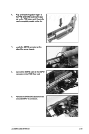
6. Locate the SGPIO connector on the side of the PIKE SAS RAID card into the card slot on the PIKE raiser card. Remove the SATA/SAS cables from the onboard SATA1-3 connectors. Ensure the card is completely seated on the PIKE Riser card. 9. Connect the SGPIO cable to the SGPIO connector on the slot. 7. Align and insert the golden fingers of the server chassis. 8. ASUS RS320Q-E7/RS12 2-21
6. Locate the SGPIO connector on the side of the PIKE SAS RAID card into the card slot on the PIKE raiser card. Remove the SATA/SAS cables from the onboard SATA1-3 connectors. Ensure the card is completely seated on the PIKE Riser card. 9. Connect the SGPIO cable to the SGPIO connector on the slot. 7. Align and insert the golden fingers of the server chassis. 8. ASUS RS320Q-E7/RS12 2-21

User Guide
Page 45
... the rear mounting hole, and place the front rail hook on the top and the bottom. 5. Adjust the rack rail to install the rack rail. ASUS RS320Q-E7/RS12 3-3 4.
... the rear mounting hole, and place the front rail hook on the top and the bottom. 5. Adjust the rack rail to install the rack rail. ASUS RS320Q-E7/RS12 3-3 4.
User Guide
Page 47
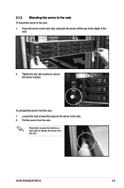
Loosen the rack screws that secured the server to release the server from the rack. Remember to press the latches on the rack rails, and push the server all the way to secure the server in place. Place the server on both sides to the rack. 2. Pull the server from the rack: 1. Tighten the two rack screws to the depth of the rack. 2. To uninstall the server from the rack. 3.1.2 Mounting the server to the rack To mount the server to the rack: 1. ASUS RS320Q-E7/RS12 3-5
Loosen the rack screws that secured the server to release the server from the rack. Remember to press the latches on the rack rails, and push the server all the way to secure the server in place. Place the server on both sides to the rack. 2. Pull the server from the rack: 1. Tighten the two rack screws to the depth of the rack. 2. To uninstall the server from the rack. 3.1.2 Mounting the server to the rack To mount the server to the rack: 1. ASUS RS320Q-E7/RS12 3-5
User Guide
Page 51
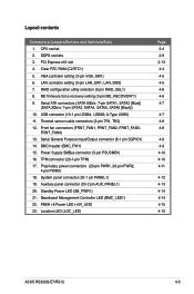
... Power LED (SB_PWR1) 21. System panel connector (20-1 pin PANEL1) 19. Location LED (LOC_LED) Page 2-4 2-9 2-13 4-4 4-5 4-5 4-6 4-6 4-7 4-7 4-8 4-8 4-9 4-9 4-10 4-10 4-11 4-12 4-13 4-14 4-14 4-15 4-15 ASUS RS320Q-E7/RS12 4-3 Front fan connectors (FRNT_FAN1, FRNT_FAN2, FRNT_FAN3, FRNT_FAN4) 13. BMC header (BMC_FW1) 15. Proprietary power connectors (20-pin PWR1, 20-pin PWR2, 4-pin PWR3) 18. VGA...
... Power LED (SB_PWR1) 21. System panel connector (20-1 pin PANEL1) 19. Location LED (LOC_LED) Page 2-4 2-9 2-13 4-4 4-5 4-5 4-6 4-6 4-7 4-7 4-8 4-8 4-9 4-9 4-10 4-10 4-11 4-12 4-13 4-14 4-14 4-15 4-15 ASUS RS320Q-E7/RS12 4-3 Front fan connectors (FRNT_FAN1, FRNT_FAN2, FRNT_FAN3, FRNT_FAN4) 13. BMC header (BMC_FW1) 15. Proprietary power connectors (20-pin PWR1, 20-pin PWR2, 4-pin PWR3) 18. VGA...

User Guide
Page 53
Set to pins 1-2 to activate the VGA feature. 3. Set to pins 1-2 to activate the Gigabit LAN feature. ASUS RS320Q-E7/RS12 4-5 VGA controller setting (3-pin VGA_SW1) This jumper allows you to enable or disable the onboard VGA controller. LAN controller setting (3-pin LAN_SW1, LAN_SW2) These jumpers allow you to enable or disable the onboard Intel® Intel 82574LGigabit LAN controllers. 2.
Set to pins 1-2 to activate the VGA feature. 3. Set to pins 1-2 to activate the Gigabit LAN feature. ASUS RS320Q-E7/RS12 4-5 VGA controller setting (3-pin VGA_SW1) This jumper allows you to enable or disable the onboard VGA controller. LAN controller setting (3-pin LAN_SW1, LAN_SW2) These jumpers allow you to enable or disable the onboard Intel® Intel 82574LGigabit LAN controllers. 2.

User Guide
Page 55
... Configuration. 2. If you installed Serial ATA hard disk drives, you can create a RAID 0, RAID 1, RAID 10, or RAID 5 configuration. USB connector (10-1 pin USB34, USB56; ASUS RS320Q-E7/RS12 4-7 A-Type USB5) These connectors are for the Serial ATA signal cables for USB 2.0 ports. These USB connectors comply with USB 2.0 specification that allows up to...
... Configuration. 2. If you installed Serial ATA hard disk drives, you can create a RAID 0, RAID 1, RAID 10, or RAID 5 configuration. USB connector (10-1 pin USB34, USB56; ASUS RS320Q-E7/RS12 4-7 A-Type USB5) These connectors are for the Serial ATA signal cables for USB 2.0 ports. These USB connectors comply with USB 2.0 specification that allows up to...

User Guide
Page 57
Serial General Purpose Input/Output connector (6-1 pin SGPIO1) This connector is used for the SGPIO peripherals for the Intel Rapid Storage Technology RAID SATA LED and LSI MegaRAID. 6. 5. ASUS RS320Q-E7/RS12 4-9 BMC header (BMC_FW1) The BMC connector on the motherboard supports an ASUS® Server Management Board 5 Series (ASMB5).
Serial General Purpose Input/Output connector (6-1 pin SGPIO1) This connector is used for the SGPIO peripherals for the Intel Rapid Storage Technology RAID SATA LED and LSI MegaRAID. 6. 5. ASUS RS320Q-E7/RS12 4-9 BMC header (BMC_FW1) The BMC connector on the motherboard supports an ASUS® Server Management Board 5 Series (ASMB5).


