
RS300-E10 Series User Manual
Page 3
...2-8 2.3.3 Installing a DIMM on a single clip DIMM socket 2-9 2.4 Hard disk drives 2-10 2.5 Expansion slot 2-14 2.5.1 Installing an expansion card to the PCIE1 slot 2-14 2.5.2 Installing a standard GPU card to the PCIE1 slot 2-15 2.5.3 Installing a large GPU card to the PCIE1 slot 2-17 2.5.4 Configuring an expansion card 2-18 2.5.5 Installing M.2 (NGFF) cards 2-20 2.6 Cable connections 2-21 2.7 SATA/SAS backplane cabling 2-22 2.8 Removable/Optional components 2-23 2.8.1 System fans 2-23 2.8.2 Installing ASUS PIKE II RAID card (optional 2-24 2.8.3 Redundant power supply module 2-26...
...2-8 2.3.3 Installing a DIMM on a single clip DIMM socket 2-9 2.4 Hard disk drives 2-10 2.5 Expansion slot 2-14 2.5.1 Installing an expansion card to the PCIE1 slot 2-14 2.5.2 Installing a standard GPU card to the PCIE1 slot 2-15 2.5.3 Installing a large GPU card to the PCIE1 slot 2-17 2.5.4 Configuring an expansion card 2-18 2.5.5 Installing M.2 (NGFF) cards 2-20 2.6 Cable connections 2-21 2.7 SATA/SAS backplane cabling 2-22 2.8 Removable/Optional components 2-23 2.8.1 System fans 2-23 2.8.2 Installing ASUS PIKE II RAID card (optional 2-24 2.8.3 Redundant power supply module 2-26...

RS300-E10 Series User Manual
Page 5
...-IO Configuration 5-30 5.6 Security menu 5-32 5.7 Boot menu 5-35 5.8 Monitor menu 5-37 5.9 Tool menu 5-38 5.10 Event Logs menu 5-38 5.10.1 Change Smbios Event Log Settings 5-38 5.10.2 View Smbios Event Log 5-39 5.11 Server Mgmt menu 5-40 5.11.1 System Event Log 5-41 5.11.2 Bmc self test log 5-42 5.11.3 BMC network configuration 5-43 5.11.4 View System Event Log 5-44 5.11.5 BMC User Settings 5-44 5.12 Save & Exit menu 5-45 Chapter 6: RAID Configuration 6.1 Setting up RAID 6-2 6.1.1 RAID definitions 6-2 6.1.2 Installing hard disk drives 6-3 6.1.3 Setting the RAID item in BIOS...
...-IO Configuration 5-30 5.6 Security menu 5-32 5.7 Boot menu 5-35 5.8 Monitor menu 5-37 5.9 Tool menu 5-38 5.10 Event Logs menu 5-38 5.10.1 Change Smbios Event Log Settings 5-38 5.10.2 View Smbios Event Log 5-39 5.11 Server Mgmt menu 5-40 5.11.1 System Event Log 5-41 5.11.2 Bmc self test log 5-42 5.11.3 BMC network configuration 5-43 5.11.4 View System Event Log 5-44 5.11.5 BMC User Settings 5-44 5.12 Save & Exit menu 5-45 Chapter 6: RAID Configuration 6.1 Setting up RAID 6-2 6.1.1 RAID definitions 6-2 6.1.2 Installing hard disk drives 6-3 6.1.3 Setting the RAID item in BIOS...
RS300-E10 Series User Manual
Page 6
... 6.2.6 Setting the Boot array in the BIOS Setup Utility 6-11 6.3 Intel® Rapid Storage Technology enterprise (Windows 6-12 6.3.1 Creating a RAID set 6-13 6.3.2 Changing a Volume Type 6-15 6.3.3 Deleting a volume 6-16 6.3.4 Preferences 6-17 Chapter 7: Driver Installation 7.1 RAID driver installation 7-2 7.1.1 Creating a USB flash drive with RAID drive 7-2 7.1.2 Installing the RAID controller driver 7-2 7.2 Management applications and utilities installation 7-5 7.3 Running the Support DVD 7-5 7.4 Installing the system drivers 7-6 Appendix P11C-C/4L/SYS block diagram A-2 Q-Code...
... 6.2.6 Setting the Boot array in the BIOS Setup Utility 6-11 6.3 Intel® Rapid Storage Technology enterprise (Windows 6-12 6.3.1 Creating a RAID set 6-13 6.3.2 Changing a Volume Type 6-15 6.3.3 Deleting a volume 6-16 6.3.4 Preferences 6-17 Chapter 7: Driver Installation 7.1 RAID driver installation 7-2 7.1.1 Creating a USB flash drive with RAID drive 7-2 7.1.2 Installing the RAID controller driver 7-2 7.2 Management applications and utilities installation 7-5 7.3 Running the Support DVD 7-5 7.4 Installing the system drivers 7-6 Appendix P11C-C/4L/SYS block diagram A-2 Q-Code...
RS300-E10 Series User Manual
Page 8
... settings through the BIOS Setup menus and describes the BIOS parameters. 6. Chapter 5: BIOS Setup This chapter tells how to perform when installing or removing system components. 3. Chapter 2: Hardware Setup This chapter lists the hardware setup procedures that comes with at least basic knowledge of configuring a server. Contents This guide contains the following parts: 1. viii Detailed descriptions of the server, including sections on front panel and rear panel specifications. 2. About this guide Audience This user guide...
... settings through the BIOS Setup menus and describes the BIOS parameters. 6. Chapter 5: BIOS Setup This chapter tells how to perform when installing or removing system components. 3. Chapter 2: Hardware Setup This chapter lists the hardware setup procedures that comes with at least basic knowledge of configuring a server. Contents This guide contains the following parts: 1. viii Detailed descriptions of the server, including sections on front panel and rear panel specifications. 2. About this guide Audience This user guide...
RS300-E10 Series User Manual
Page 12
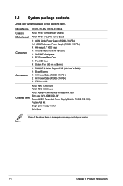
... Chassis Motherboard ASUS P11C-C/4L/SYS Server Board Component 1 x 400W Single Power Supply (RS300-E10-PS4) 1+1 450W Redundant Power Supply (RS300-E10-RS4) 4 x Hot-swap 3.5" HDD trays 1 x miniSAS HD to miniSAS HD cable 1 x SAS/SATA Backplane 1 x PCI Express Riser Card 1 x Front I/O Board 4 x System Fans (40 mm x 28 mm) Accessories 1 x RS300-E10 Series Support DVD (with User's Guide) 1 x Bag of Screws 1 x AC Power Cable (RS300-E10-PS4) 2 x AC Power Cable (RS300-E10-RS4) 1 x CPU Heatsink ASUS PIKE II 3008 card ASUS PIKE II 3108 card ASUS ASMB9-iKVM Remote management card Slim-type DVD-ROM...
... Chassis Motherboard ASUS P11C-C/4L/SYS Server Board Component 1 x 400W Single Power Supply (RS300-E10-PS4) 1+1 450W Redundant Power Supply (RS300-E10-RS4) 4 x Hot-swap 3.5" HDD trays 1 x miniSAS HD to miniSAS HD cable 1 x SAS/SATA Backplane 1 x PCI Express Riser Card 1 x Front I/O Board 4 x System Fans (40 mm x 28 mm) Accessories 1 x RS300-E10 Series Support DVD (with User's Guide) 1 x Bag of Screws 1 x AC Power Cable (RS300-E10-PS4) 2 x AC Power Cable (RS300-E10-RS4) 1 x CPU Heatsink ASUS PIKE II 3008 card ASUS PIKE II 3108 card ASUS ASMB9-iKVM Remote management card Slim-type DVD-ROM...
RS300-E10 Series User Manual
Page 15
... RS300-E10-PS4 Rear I/O Ports 2 x USB 3.1 ports 2 x USB 3.0 ports 1 x VGA port 4 x RJ-45 ports 1 x RJ-45 port (One for ASMB9iKVM) (Optional) Rear Switch/LED: 2 x USB 3.1 ports 2 x USB 3.0 ports 1 x VGA port 1 x External Serial Port 4 x RJ-45 ports 1 x RJ-45 port (One for ASMB9iKVM) (Optional) 1 x Q-Code/Port 80 LED 1 x Power switch Front Switch/LED: Switch/LED 1 x Power switch/LED 1 x Location switch/LED 1 x Reset switch 1 x HDD Access LED 1 x Message LED OS Support LAN 1-4 LED Please find the latest OS support from http://www.asus.com/ Software ASUS Control Center Management...
... RS300-E10-PS4 Rear I/O Ports 2 x USB 3.1 ports 2 x USB 3.0 ports 1 x VGA port 4 x RJ-45 ports 1 x RJ-45 port (One for ASMB9iKVM) (Optional) Rear Switch/LED: 2 x USB 3.1 ports 2 x USB 3.0 ports 1 x VGA port 1 x External Serial Port 4 x RJ-45 ports 1 x RJ-45 port (One for ASMB9iKVM) (Optional) 1 x Q-Code/Port 80 LED 1 x Power switch Front Switch/LED: Switch/LED 1 x Power switch/LED 1 x Location switch/LED 1 x Reset switch 1 x HDD Access LED 1 x Message LED OS Support LAN 1-4 LED Please find the latest OS support from http://www.asus.com/ Software ASUS Control Center Management...

RS300-E10 Series User Manual
Page 17
... slot Riser Card 3. Slim-type optical drive 9. 1.6 Internal features The barebone server includes the basic components as shown. Connect a USB floppy disk drive to use a floppy disk. System fans 5. ASUS P11C-C/4L/SYS Server Board 4. SAS / SATA backplane (hidden) 6. SSD Cage 10. RS300-E10-RS4 1. 1+1 Redundant 450W 80 PLUS Gold Power Supply 2. Front I/O boards (hidden) 8. Asset Tag The barebone server does not include a floppy disk drive. HDD tray 1-4 7. WARNING HAZARDOUS MOVING PARTS KEEP FINGERS AND OTHER BODY PARTS AWAY ASUS RS300-E10 Series 1-7 Turn...
... slot Riser Card 3. Slim-type optical drive 9. 1.6 Internal features The barebone server includes the basic components as shown. Connect a USB floppy disk drive to use a floppy disk. System fans 5. ASUS P11C-C/4L/SYS Server Board 4. SAS / SATA backplane (hidden) 6. SSD Cage 10. RS300-E10-RS4 1. 1+1 Redundant 450W 80 PLUS Gold Power Supply 2. Front I/O boards (hidden) 8. Asset Tag The barebone server does not include a floppy disk drive. HDD tray 1-4 7. WARNING HAZARDOUS MOVING PARTS KEEP FINGERS AND OTHER BODY PARTS AWAY ASUS RS300-E10 Series 1-7 Turn...
RS300-E10 Series User Manual
Page 18
... fans 5. WARNING HAZARDOUS MOVING PARTS KEEP FINGERS AND OTHER BODY PARTS AWAY 1-8 Chapter 1: Product Introduction PCI Express slot Riser Card 3. SAS / SATA backplane (hidden) 6. SSD Cage 10. Single 400W 80 PLUS Gold Power Supply 2. Slim-type optical drive 9. Turn off the system power and detach the power supply before removing or replacing any of the USB ports on the front or rear panel if you need to use a floppy disk. HDD tray 1-4 7. Asset Tag The barebone server...
... fans 5. WARNING HAZARDOUS MOVING PARTS KEEP FINGERS AND OTHER BODY PARTS AWAY 1-8 Chapter 1: Product Introduction PCI Express slot Riser Card 3. SAS / SATA backplane (hidden) 6. SSD Cage 10. Single 400W 80 PLUS Gold Power Supply 2. Slim-type optical drive 9. Turn off the system power and detach the power supply before removing or replacing any of the USB ports on the front or rear panel if you need to use a floppy disk. HDD tray 1-4 7. Asset Tag The barebone server...

RS300-E10 Series User Manual
Page 19
...1.7.1 Front panel LEDs 4 3 2 1 LAN 4 LED LAN 3 LED LAN 2 LED LAN 1 LED Location switch Power button HDD LED Message LED LED Icon Power LED HDD Access LED Message LED Location LED LAN LEDs Display status Description ON System power ON OFF Blinking OFF ON OFF ON OFF Blinking ON No activity Read/write data into the HDD System is present ASUS RS300-E10 Series 1-9 no incoming event A hardware monitor event is indicated Normal status Location switch is pressed (Press the location switch again to turn off) No LAN connection LAN is transmitting or receiving data LAN connection is...
...1.7.1 Front panel LEDs 4 3 2 1 LAN 4 LED LAN 3 LED LAN 2 LED LAN 1 LED Location switch Power button HDD LED Message LED LED Icon Power LED HDD Access LED Message LED Location LED LAN LEDs Display status Description ON System power ON OFF Blinking OFF ON OFF ON OFF Blinking ON No activity Read/write data into the HDD System is present ASUS RS300-E10 Series 1-9 no incoming event A hardware monitor event is indicated Normal status Location switch is pressed (Press the location switch again to turn off) No LAN connection LAN is transmitting or receiving data LAN connection is...
RS300-E10 Series User Manual
Page 38
... Floppy Disk Controller 7* 15 -- 8 3 System CMOS/Real Time Clock 9* 4 ACPI Mode when used 10* 5 IRQ Holder for PCI Steering 11* 6 IRQ Holder for PCI Steering 12* 7 PS/2 Compatible Mouse Port 13 8 Numeric Data Processor 14* 9 Primary IDE Channel 15* 10 Secondary IDE Channel * These IRQs are usually available for the expansion card. Install the software drivers for ISA or PCI devices. 2-18 Chapter 2: Hardware Information 2.5.4 Configuring an expansion card After installing the expansion card, configure...
... Floppy Disk Controller 7* 15 -- 8 3 System CMOS/Real Time Clock 9* 4 ACPI Mode when used 10* 5 IRQ Holder for PCI Steering 11* 6 IRQ Holder for PCI Steering 12* 7 PS/2 Compatible Mouse Port 13 8 Numeric Data Processor 14* 9 Primary IDE Channel 15* 10 Secondary IDE Channel * These IRQs are usually available for the expansion card. Install the software drivers for ISA or PCI devices. 2-18 Chapter 2: Hardware Information 2.5.4 Configuring an expansion card After installing the expansion card, configure...

RS300-E10 Series User Manual
Page 68
... a mini Serial Attached SCSI (SAS) HD connector, the storage technology that allows up to 6Gb/s of Serial ATA hard disks installed. • When the M.2 connector is operating in SATA mode, SATA connector 5 and 6 (SATA 6 Gbps_5-6) will be disabled. 2. Serial ATA 6.0Gb/s connectors (7-pin SATA5-6 [Gray]) Supported by the Intel® C242 chipset, these connectors are for the Serial ATA signal cables for Serial ATA hard disk drives that supports Serial ATA. If you installed Serial ATA hard disk drives, you can create a RAID 0, RAID 1, RAID 10, or RAID 5 configuration...
... a mini Serial Attached SCSI (SAS) HD connector, the storage technology that allows up to 6Gb/s of Serial ATA hard disks installed. • When the M.2 connector is operating in SATA mode, SATA connector 5 and 6 (SATA 6 Gbps_5-6) will be disabled. 2. Serial ATA 6.0Gb/s connectors (7-pin SATA5-6 [Gray]) Supported by the Intel® C242 chipset, these connectors are for the Serial ATA signal cables for Serial ATA hard disk drives that supports Serial ATA. If you installed Serial ATA hard disk drives, you can create a RAID 0, RAID 1, RAID 10, or RAID 5 configuration...

RS300-E10 Series User Manual
Page 95
... become user-configurable with set to [Power On], the system will reboot after an AC power loss. Configuration options: [Power Off] [Power On] [Last State] Power On By PCI-E/PCI [Disabled] [Disabled] Disables the PCI or PCIE devices to generate a wake event. [Enabled] Enables the PCI or PCIE devices to generate a wake event. Configuration options: [Disabled] [Enabled] ASUS RS300-E10 Series 5-15 When set values. 5.4.6 Runtime Error Logging Settings Runtime Error Logging System Enabling [Enabled] This item allows you to enable or disable Security Device Support. When set...
... become user-configurable with set to [Power On], the system will reboot after an AC power loss. Configuration options: [Power Off] [Power On] [Last State] Power On By PCI-E/PCI [Disabled] [Disabled] Disables the PCI or PCIE devices to generate a wake event. [Enabled] Enables the PCI or PCIE devices to generate a wake event. Configuration options: [Disabled] [Enabled] ASUS RS300-E10 Series 5-15 When set values. 5.4.6 Runtime Error Logging Settings Runtime Error Logging System Enabling [Enabled] This item allows you to enable or disable Security Device Support. When set...

RS300-E10 Series User Manual
Page 100
5.4.10 PCI Subsystem Settings Allows you to enable or disable 64-bit capable devices to configure PCI, PCI-X, and PCI Express Settings. It only works if the system supports 64-bit PCI decoding. Above 4G Decoding [Disabled] Allows you to be decoded in above 4G address space. Configuration options: [Disabled] [Enabled] 5.4.11 USB Configuration 5-20 Chapter 5: BIOS Setup
5.4.10 PCI Subsystem Settings Allows you to enable or disable 64-bit capable devices to configure PCI, PCI-X, and PCI Express Settings. It only works if the system supports 64-bit PCI decoding. Above 4G Decoding [Disabled] Allows you to be decoded in above 4G address space. Configuration options: [Disabled] [Enabled] 5.4.11 USB Configuration 5-20 Chapter 5: BIOS Setup

RS300-E10 Series User Manual
Page 101
... FDD] [Hard Disk] [CD-ROM] ASUS RS300-E10 Series 5-21 If detected, the USB controller legacy mode is disabled. XHCI Hand-off support. It cannot be used only for devices connected. The values range from 1 to adjust the value. Mass Storage Devices Allows you to select the mass storage device emulation type for the BIOS setup program. Device power-up delay in seconds. Configuration options: [Disabled] [Enabled] USB transfer time-out [20 sec] Allows you to set the device power-up...
... FDD] [Hard Disk] [CD-ROM] ASUS RS300-E10 Series 5-21 If detected, the USB controller legacy mode is disabled. XHCI Hand-off support. It cannot be used only for devices connected. The values range from 1 to adjust the value. Mass Storage Devices Allows you to select the mass storage device emulation type for the BIOS setup program. Device power-up delay in seconds. Configuration options: [Disabled] [Enabled] USB transfer time-out [20 sec] Allows you to set the device power-up...

RS300-E10 Series User Manual
Page 106
... changing the settings of the Chipset menu items. Incorrect field values can cause the system to malfunction. 5.5.1 System Agent (SA) Configuration Memory Configuration Maximum Memory Frequency [Auto] Allows you to enable or disable Fast Boot. 5.5 Chipset menu The Chipset menu allow you to enable or disable the ECC support. Configuration options: [Auto] [2133] [2400] [2666] ECC Support [Enabled] Allows you to enable or disable Memory Scrambler. Configuration options: [Disabled] [Enabled] 5-26 Chapter 5: BIOS Setup Configuration options: [Disabled] [Enabled] Memory Scrambler [Enabled...
... changing the settings of the Chipset menu items. Incorrect field values can cause the system to malfunction. 5.5.1 System Agent (SA) Configuration Memory Configuration Maximum Memory Frequency [Auto] Allows you to enable or disable Fast Boot. 5.5 Chipset menu The Chipset menu allow you to enable or disable the ECC support. Configuration options: [Auto] [2133] [2400] [2666] ECC Support [Enabled] Allows you to enable or disable Memory Scrambler. Configuration options: [Disabled] [Enabled] 5-26 Chapter 5: BIOS Setup Configuration options: [Disabled] [Enabled] Memory Scrambler [Enabled...

RS300-E10 Series User Manual
Page 110
...] Hot Plug [Enabled] Allows you set the SATA Controller(s) to [Enabled]. SATA Mode Selection [AHCI] Allows you to identify the SATA port is connected to a solid state drive or a hard disk drive Configuration options: [Hard Disk Drive] [Solid State Drive] 5-30 Chapter 5: BIOS Setup Configuration options: [Disabled] [Enabled] SATA Device Type [Hard Disk Drive] Allows you to select the SATA controllers operation. Configuration options: [AHCI] [RAID] Serial ATA Port 1-6 Port 1-6 [Enabled] Allows you to enable or disable control of active state power management of DMI link. Configuration...
...] Hot Plug [Enabled] Allows you set the SATA Controller(s) to [Enabled]. SATA Mode Selection [AHCI] Allows you to identify the SATA port is connected to a solid state drive or a hard disk drive Configuration options: [Hard Disk Drive] [Solid State Drive] 5-30 Chapter 5: BIOS Setup Configuration options: [Disabled] [Enabled] SATA Device Type [Hard Disk Drive] Allows you to select the SATA controllers operation. Configuration options: [AHCI] [RAID] Serial ATA Port 1-6 Port 1-6 [Enabled] Allows you to enable or disable control of active state power management of DMI link. Configuration...

RS300-E10 Series User Manual
Page 128
... ROM Utility with RAID 0, RAID 1, RAID 10, and RAID 5 support. 6.1.1 RAID definitions RAID 0 (Data striping) optimizes two identical hard disk drives to read and write data in a created RAID set, copy first the RAID driver from one drive fails, the disk array management software directs all the benefits of RAID 5 configuration include better HDD performance, fault tolerance, and higher storage capacity. Two hard disks perform the same work as it contains a complete copy of data from the support DVD to a floppy disk before you install...
... ROM Utility with RAID 0, RAID 1, RAID 10, and RAID 5 support. 6.1.1 RAID definitions RAID 0 (Data striping) optimizes two identical hard disk drives to read and write data in a created RAID set, copy first the RAID driver from one drive fails, the disk array management software directs all the benefits of RAID 5 configuration include better HDD performance, fault tolerance, and higher storage capacity. Two hard disks perform the same work as it contains a complete copy of data from the support DVD to a floppy disk before you install...
RS300-E10 Series User Manual
Page 129
...POST. 2. Set SATA Mode Selection to the Chipset Menu > PCH-IO Configuration > SATA And RSTe Configuration, then press . 3. Go to [RAID]. 4. ASUS RS300-E10 Series 6-3 For optimal performance, install identical drives of each drive. 6.1.3 Setting the RAID item in BIOS You must set the RAID item in the system user guide. 2. To install the SATA hard disks for RAID set from SATA hard disk drives attached to the SATA connector on the motherboard. 3. Connect a SATA power cable to the power connector on entering and navigating through the BIOS Setup. Install the SATA hard disks...
...POST. 2. Set SATA Mode Selection to the Chipset Menu > PCH-IO Configuration > SATA And RSTe Configuration, then press . 3. Go to [RAID]. 4. ASUS RS300-E10 Series 6-3 For optimal performance, install identical drives of each drive. 6.1.3 Setting the RAID item in BIOS You must set the RAID item in the system user guide. 2. To install the SATA hard disks for RAID set from SATA hard disk drives attached to the SATA connector on the motherboard. 3. Connect a SATA power cable to the power connector on entering and navigating through the BIOS Setup. Install the SATA hard disks...
RS300-E10 Series User Manual
Page 148
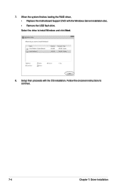
Select the drive to continue. 7-4 Chapter 7: Driver Installation Setup then proceeds with the Windows Server installation disc. • Remove the USB flash drive. When the system finishes loading the RAID driver, • Replace the motherboard Support DVD with the OS installation. Follow the onscreen instructions to install Windows and click Next. 8. 7.
Select the drive to continue. 7-4 Chapter 7: Driver Installation Setup then proceeds with the Windows Server installation disc. • Remove the USB flash drive. When the system finishes loading the RAID driver, • Replace the motherboard Support DVD with the OS installation. Follow the onscreen instructions to install Windows and click Next. 8. 7.
RS300-E10 Series User Manual
Page 157
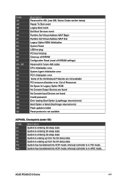
... Status Codes section below) Ready To Boot event Legacy Boot event Exit Boot Services event Runtime Set Virtual Address MAP Begin Runtime Set Virtual Address MAP End Legacy Option ROM Initialization System Reset USB hot plug PCI bus hot plug Clean-up from the S3 sleep state System is waking up of NVRAM Configuration Reset (reset of NVRAM settings) Reserved for Legacy Option ROM No Console Output Devices are found No Console Input Devices are found Invalid password Error loading Boot Option (LoadImage returned error) Boot Option is failed...
... Status Codes section below) Ready To Boot event Legacy Boot event Exit Boot Services event Runtime Set Virtual Address MAP Begin Runtime Set Virtual Address MAP End Legacy Option ROM Initialization System Reset USB hot plug PCI bus hot plug Clean-up from the S3 sleep state System is waking up of NVRAM Configuration Reset (reset of NVRAM settings) Reserved for Legacy Option ROM No Console Output Devices are found No Console Input Devices are found Invalid password Error loading Boot Option (LoadImage returned error) Boot Option is failed...


