User Manual
Page 11
It includes sections on front panel and rear panel specifications. ASUS RS161-E2/PA2 1-1 Product introduction Chapter 1 This chapter describes the general features of the chassis kit.
It includes sections on front panel and rear panel specifications. ASUS RS161-E2/PA2 1-1 Product introduction Chapter 1 This chapter describes the general features of the chassis kit.

User Manual
Page 13
... 4 GB DDR availability) LAN 2 x Broadcom® BCM5721 Gigabit PCI-E LAN controllers VGA ATI RAGE-XL PCI-based VGA controller with 8 MB display memory Expansion slots 2 x PCI Express™ x16 slots (x8 link) 1 x mini-PCI socket for AMD Opteron™ 64 processors...: Tested only up to 16 GB on the motherboard. 1.2 System specifications The ASUS RS161-E2 (PA2) is a 1U barebone server system featuring the ASUS K8N-DRE motherboard. RAID 0, RAID 1, and JBOD configurations Management ASUS Server Web-based Management (ASWM) Monitoring Voltage, temperature, and fan speed monitoring ...
... 4 GB DDR availability) LAN 2 x Broadcom® BCM5721 Gigabit PCI-E LAN controllers VGA ATI RAGE-XL PCI-based VGA controller with 8 MB display memory Expansion slots 2 x PCI Express™ x16 slots (x8 link) 1 x mini-PCI socket for AMD Opteron™ 64 processors...: Tested only up to 16 GB on the motherboard. 1.2 System specifications The ASUS RS161-E2 (PA2) is a 1U barebone server system featuring the ASUS K8N-DRE motherboard. RAID 0, RAID 1, and JBOD configurations Management ASUS Server Web-based Management (ASWM) Monitoring Voltage, temperature, and fan speed monitoring ...
User Manual
Page 15
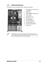
...) to any of the USB ports on the front or rear panel if you need to use a floppy disk. Hot-swap HDD tray 1 5 9. Power supply 5. ASUS RS161-E2/PA2 1-5 SATA backplane 5 6 5 8. ASUS K8N-DRE motherboard 3 4.
...) to any of the USB ports on the front or rear panel if you need to use a floppy disk. Hot-swap HDD tray 1 5 9. Power supply 5. ASUS RS161-E2/PA2 1-5 SATA backplane 5 6 5 8. ASUS K8N-DRE motherboard 3 4.
User Manual
Page 17
Chapter 2 This chapter lists the hardware setup procedures that you have to perform when installing or removing system components. Hardware setup ASUS RS161-E2/PA2 2-1
Chapter 2 This chapter lists the hardware setup procedures that you have to perform when installing or removing system components. Hardware setup ASUS RS161-E2/PA2 2-1

User Manual
Page 19
Position the cover on top of the chassis with the thumbscrews on each side) are aligned to secure the cover. Thumbscrews 5. Drive in place. 4. Slide the cover toward the front until it snaps in the screw on the chassis. ASUS RS161-E2/PA2 2-3 Tighten the thumbscrews on the rear to the grooves on both sides of about half an inch from the front panel. Grooves 3. 2.1.2 Installing the cover 1. Make sure that the side markings on the cover (two on the rear, and leaving a gap of the chassis. Side markings 2.
Position the cover on top of the chassis with the thumbscrews on each side) are aligned to secure the cover. Thumbscrews 5. Drive in place. 4. Slide the cover toward the front until it snaps in the screw on the chassis. ASUS RS161-E2/PA2 2-3 Tighten the thumbscrews on the rear to the grooves on both sides of about half an inch from the front panel. Grooves 3. 2.1.2 Installing the cover 1. Make sure that the side markings on the cover (two on the rear, and leaving a gap of the chassis. Side markings 2.

User Manual
Page 21
The 128-bit-wide data paths of the notched corner on the CPU. ASUS RS161-E2/PA2 2-5 Notched corner 2.3.2 Installing the CPU To install a CPU: 1. This corner should match a specific corner on the motherboard. K8N-DRE ¤ CPU2 CPU1 CPU2 CPU1 K8N-...
The 128-bit-wide data paths of the notched corner on the CPU. ASUS RS161-E2/PA2 2-5 Notched corner 2.3.2 Installing the CPU To install a CPU: 1. This corner should match a specific corner on the motherboard. K8N-DRE ¤ CPU2 CPU1 CPU2 CPU1 K8N-...
User Manual
Page 23
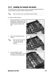
... the CPU heatsink: 1. otherwise, the CPU will overheat. 3. If you use only qualified heatsink assembly. Secure the heatsink with the support plate stand offs. 2. ASUS RS161-E2/PA2 2-7 2.3.3 Installing the heatsink and airduct The AMD Opteron™ 64 processors require a specially designed heatsink to install the second heatsink. Make sure that the heatsink...
... the CPU heatsink: 1. otherwise, the CPU will overheat. 3. If you use only qualified heatsink assembly. Secure the heatsink with the support plate stand offs. 2. ASUS RS161-E2/PA2 2-7 2.3.3 Installing the heatsink and airduct The AMD Opteron™ 64 processors require a specially designed heatsink to install the second heatsink. Make sure that the heatsink...

User Manual
Page 25
The following figure illustrates the location of the sockets: K8N-DRE ¤ DIMM_A1 DIMM_A2 DIMM_B1 DIMM_B2 DIMM_D2 DIMM_D1 DIMM_C2 DIMM_C1 104 Pins 80 Pins 80 Pins 104 Pins K8N-DRE 184-pin DDR DIMM sockets For CPU 1 Channel A Channel B For CPU 2 Channel A Channel B Sockets DIMM_A1 and DIMM_A2 DIMM_B1 and DIMM_B2 Sockets DIMM_C1 and DIMM_C2 DIMM_D1 and DIMM_D2 ASUS RS161-E2/PA2 2-9 2.4 System memory 2.4.1 Overview The motherboard comes with eight 184-pin Double Data Rate (DDR) Dual Inline Memory Modules (DIMM) sockets.
The following figure illustrates the location of the sockets: K8N-DRE ¤ DIMM_A1 DIMM_A2 DIMM_B1 DIMM_B2 DIMM_D2 DIMM_D1 DIMM_C2 DIMM_C1 104 Pins 80 Pins 80 Pins 104 Pins K8N-DRE 184-pin DDR DIMM sockets For CPU 1 Channel A Channel B For CPU 2 Channel A Channel B Sockets DIMM_A1 and DIMM_A2 DIMM_B1 and DIMM_B2 Sockets DIMM_C1 and DIMM_C2 DIMM_D1 and DIMM_D2 ASUS RS161-E2/PA2 2-9 2.4 System memory 2.4.1 Overview The motherboard comes with eight 184-pin Double Data Rate (DDR) Dual Inline Memory Modules (DIMM) sockets.
User Manual
Page 27
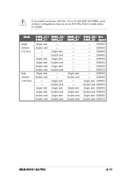
... rank DIMM_B2/ Max DIMM_D2 Speed - DDR400 - DDR400 Single rank DDR400 Double rank DDR400 Single rank DDR400 Double rank DDR400 Single rank DDR400 Double rank DDR333 ASUS RS161-E2/PA2 2-11
... rank DIMM_B2/ Max DIMM_D2 Speed - DDR400 - DDR400 Single rank DDR400 Double rank DDR400 Single rank DDR400 Double rank DDR400 Single rank DDR400 Double rank DDR333 ASUS RS161-E2/PA2 2-11
User Manual
Page 29
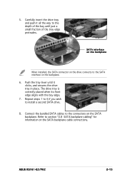
... way to install a second SATA drive. 8. Connect the bundled SATA cables to section "2.8 SATA backplane cabling" for information on the SATA backplane cable connections. ASUS RS161-E2/PA2 2-13 The drive tray is correctly placed when its front edge aligns with the bay edge. 7. Refer to the connectors on the backplane. 6. SATA interface...
... way to install a second SATA drive. 8. Connect the bundled SATA cables to section "2.8 SATA backplane cabling" for information on the SATA backplane cable connections. ASUS RS161-E2/PA2 2-13 The drive tray is correctly placed when its front edge aligns with the bay edge. 7. Refer to the connectors on the backplane. 6. SATA interface...
User Manual
Page 31
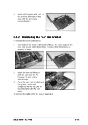
ASUS RS161-E2/PA2 2-15 The three pegs on the riser card should match these holes to the card, if applicable. Press the riser card bracket until the golden ...
ASUS RS161-E2/PA2 2-15 The three pegs on the riser card should match these holes to the card, if applicable. Press the riser card bracket until the golden ...
User Manual
Page 33
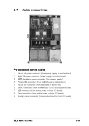
SATA backplane power connector (from motherboard to front I /O board) ASUS RS161-E2/PA2 2-17 Device fan connector (from backplane to SATA backplane board) 7. SATA connectors (from motherboard to device fan) 6. Primary IDE connector (from motherboard to motherboard) 3. Auxiliary ...
SATA backplane power connector (from motherboard to front I /O board) ASUS RS161-E2/PA2 2-17 Device fan connector (from backplane to SATA backplane board) 7. SATA connectors (from motherboard to device fan) 6. Primary IDE connector (from motherboard to motherboard) 3. Auxiliary ...
User Manual
Page 35
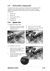
... fans 2. Disconnect a system fan cable from the fan connector on the fan side. 2. Connect the system fan cable to the fan cage. Device fan 3. ASUS RS161-E2/PA2 2-19 2.9 Removable components You may need to remove previously installed system components when installing or removing system devices, or when you need to replace defective...
... fans 2. Disconnect a system fan cable from the fan connector on the fan side. 2. Connect the system fan cable to the fan cage. Device fan 3. ASUS RS161-E2/PA2 2-19 2.9 Removable components You may need to remove previously installed system components when installing or removing system devices, or when you need to replace defective...
User Manual
Page 37
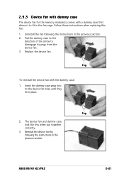
... To reinstall the device fan with a dummy case that allows it to disengage its pegs from the device fan. 3. Peg 2. Replace the device fan. ASUS RS161-E2/PA2 2-21 2.9.3 Device fan with dummy case The device fan for the memory module(s) comes with the dummy case: 1. Insert the dummy case pegs into to...
... To reinstall the device fan with a dummy case that allows it to disengage its pegs from the device fan. 3. Peg 2. Replace the device fan. ASUS RS161-E2/PA2 2-21 2.9.3 Device fan with dummy case The device fan for the memory module(s) comes with the dummy case: 1. Insert the dummy case pegs into to...
User Manual
Page 39
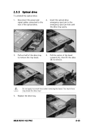
Replace the drive tray. Too much force when removing the bezel. Pull the center of the drive tray to remove. Do not apply too much force may break the drive tray! 5. Pull out half of the bezel outward (A), then lift the sides (B) to remove the tray bezel. 4. Insert the optical drive emergency eject pin to the rear of the optical drive. 2. Disconnect the power and signal cables connected to the emergency eject pin hole until the drive tray ejects. 3. 2.9.5 Optical drive To uninstall the optical drive: 1. ASUS RS161-E2/PA2 2-23
Replace the drive tray. Too much force when removing the bezel. Pull the center of the drive tray to remove. Do not apply too much force may break the drive tray! 5. Pull out half of the bezel outward (A), then lift the sides (B) to remove the tray bezel. 4. Insert the optical drive emergency eject pin to the rear of the optical drive. 2. Disconnect the power and signal cables connected to the emergency eject pin hole until the drive tray ejects. 3. 2.9.5 Optical drive To uninstall the optical drive: 1. ASUS RS161-E2/PA2 2-23
User Manual
Page 41
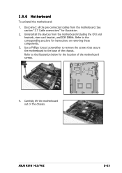
Disconnect all the devices from the motherboard. ASUS RS161-E2/PA2 2-25 Use a Phillips (cross) screwdriver to remove the screws that secure the motherboard to the corresponding sections for instructions on removing these components. 3. K8N-DRE &#...
Disconnect all the devices from the motherboard. ASUS RS161-E2/PA2 2-25 Use a Phillips (cross) screwdriver to remove the screws that secure the motherboard to the corresponding sections for instructions on removing these components. 3. K8N-DRE &#...

User Manual
Page 43
Installation options Chapter 3 This chapter describes how to install the optional components and devices into the barebone server. ASUS RS161-E2/PA2 2-1
Installation options Chapter 3 This chapter describes how to install the optional components and devices into the barebone server. ASUS RS161-E2/PA2 2-1

User Manual
Page 45
Repeat steps 2 to 7 to the rack: 1. ASUS RS161-E2 (PA2) 3-3 Find the r e a r 1 U s p a c e that corresponds to the f r o n t 1 U s p a c e where you wish to the 1U space. 4. Select one unit of a rack rail pair to install the barebone server. 2. ...
Repeat steps 2 to 7 to the rack: 1. ASUS RS161-E2 (PA2) 3-3 Find the r e a r 1 U s p a c e that corresponds to the f r o n t 1 U s p a c e where you wish to the 1U space. 4. Select one unit of a rack rail pair to install the barebone server. 2. ...

User Manual
Page 47
This chapter includes the motherboard layout, jumper settings, and connector locations ASUS RS161-E2/PA2 2-1 Motherboard info Chapter 4 This chapter gives information about the motherboard that comes with the server.
This chapter includes the motherboard layout, jumper settings, and connector locations ASUS RS161-E2/PA2 2-1 Motherboard info Chapter 4 This chapter gives information about the motherboard that comes with the server.

User Manual
Page 51
... controller. K8N-DRE ¤ KBPWR1 1 2 +5VSB 2 3 +5V (Default) K8N-DRE Keyboard power setting 3 . K8N-DRE ¤ LAN1_EN1 1 2 Enable (Default) 2 3 Disable K8N-DRE LAN1_EN1 setting ASUS RS161-E2 (PA2) 4-5 Set to pins 1-2 to wake up feature. Set this jumper to pins 1-2 (+5VSB) to activate the Gigabit LAN feature. This feature requires an ATX power...
... controller. K8N-DRE ¤ KBPWR1 1 2 +5VSB 2 3 +5V (Default) K8N-DRE Keyboard power setting 3 . K8N-DRE ¤ LAN1_EN1 1 2 Enable (Default) 2 3 Disable K8N-DRE LAN1_EN1 setting ASUS RS161-E2 (PA2) 4-5 Set to pins 1-2 to wake up feature. Set this jumper to pins 1-2 (+5VSB) to activate the Gigabit LAN feature. This feature requires an ATX power...