User Guide
Page 5
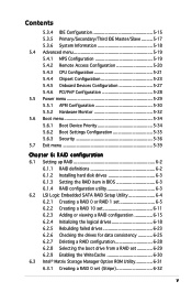
... Configuration 5-15 5.3.5 Primary/Secondary/Third IDE Master/Slave ......... 5-17 5.3.6 System Information 5-18 5.4 Advanced menu 5-19 5.4.1 MPS Configuration 5-19 5.4.2 Remote Access Configuration 5-20 5.4.3 CPU Configuration 5-21 5.4.4 Chipset Configuration 5-23 5.4.5 Onboard Devices Configuration 5-27 5.4.6 PCI/PnP Configuration 5-28 5.5 Power menu 5-29 5.5.1 APM Configuration 5-30 5.5.2 Hardware Monitor 5-32 5.6 Boot menu 5-34 5.6.1 Boot Device Priority...
... Configuration 5-15 5.3.5 Primary/Secondary/Third IDE Master/Slave ......... 5-17 5.3.6 System Information 5-18 5.4 Advanced menu 5-19 5.4.1 MPS Configuration 5-19 5.4.2 Remote Access Configuration 5-20 5.4.3 CPU Configuration 5-21 5.4.4 Chipset Configuration 5-23 5.4.5 Onboard Devices Configuration 5-27 5.4.6 PCI/PnP Configuration 5-28 5.5 Power menu 5-29 5.5.1 APM Configuration 5-30 5.5.2 Hardware Monitor 5-32 5.6 Boot menu 5-34 5.6.1 Boot Device Priority...

User Guide
Page 13
...and includes the latest technologies through the chipsets embedded on the motherboard. ASUS RS120-E3/PA4 1-3 RAID 0, RAID 1, RAID 10, or software RAID 5 configuration using the LSI Logic Embedded SATA RAID controller Management ASUS Server Web-based Management (ASWM) ...configuration using the Intel® Matrix Storage Manager - 1.2 System specifications The ASUS RS120-E3/PA4 is a 1U barebone server system featuring the ASUS P5MT-R motherboard. Chassis Rackmount 1U (R10) Motherboard ASUS P5MT-R Chipset North Bridge : Intel® E7230 Memory Controller Hub (MCH) South Bridge ...
...and includes the latest technologies through the chipsets embedded on the motherboard. ASUS RS120-E3/PA4 1-3 RAID 0, RAID 1, RAID 10, or software RAID 5 configuration using the LSI Logic Embedded SATA RAID controller Management ASUS Server Web-based Management (ASWM) ...configuration using the Intel® Matrix Storage Manager - 1.2 System specifications The ASUS RS120-E3/PA4 is a 1U barebone server system featuring the ASUS P5MT-R motherboard. Chassis Rackmount 1U (R10) Motherboard ASUS P5MT-R Chipset North Bridge : Intel® E7230 Memory Controller Hub (MCH) South Bridge ...
User Guide
Page 25
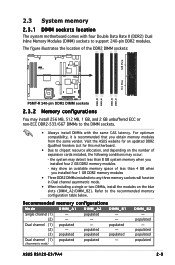
...populated - (3) populated populated populated Dual channel (1) populated populated - (Asymmetric mode) DIMM_B2 - Visit the ASUS website for an updated DDR2 Qualified Vendors List for this motherboard. • Due to the recommended memory... For optimum compatibility, it is recommended that you installed four 2 GB DDR2 memory modules - Refer to chipset resource allocation, and depending on the blue slots (DIMM_A2/DIMM_B2). The figure illustrates the location of the ...240-pin DDR2 modules. populated - (2) - - - populated populated populated ASUS RS120-E3/PA4 2-9
...populated - (3) populated populated populated Dual channel (1) populated populated - (Asymmetric mode) DIMM_B2 - Visit the ASUS website for an updated DDR2 Qualified Vendors List for this motherboard. • Due to the recommended memory... For optimum compatibility, it is recommended that you installed four 2 GB DDR2 memory modules - Refer to chipset resource allocation, and depending on the blue slots (DIMM_A2/DIMM_B2). The figure illustrates the location of the ...240-pin DDR2 modules. populated - (2) - - - populated populated populated ASUS RS120-E3/PA4 2-9
User Guide
Page 82
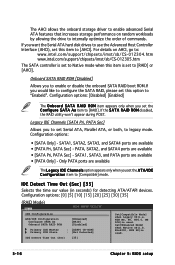
... onboard storage driver to enable advanced Serial ATA features that increases storage performance on AHCI, go to: www.intel.com/support/chipsets/imst/sb/CS-012304.htm www.intel.com/support/chipsets/imst/sb/CS-012305.htm The SATA controller is set the A T A/I D E C o n f i g u r a t i o n item to [Compatible] mode. Only PATA ports are available...
... onboard storage driver to enable advanced Serial ATA features that increases storage performance on AHCI, go to: www.intel.com/support/chipsets/imst/sb/CS-012304.htm www.intel.com/support/chipsets/imst/sb/CS-012305.htm The SATA controller is set the A T A/I D E C o n f i g u r a t i o n item to [Compatible] mode. Only PATA ports are available...
User Guide
Page 85
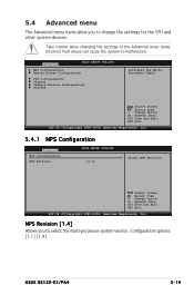
Advanced BIOS SETUP UTILITY MPS Configuration Remote Access Configuration CPU Configuration Chipset Onboard Devices Configuration PCI/PnP Configure the MultiProcessor Table. Change Option F1 General Help F10 Save and Exit ESC Exit...1985-2004, American Megatrends, Inc. 5.4.1 MPS Configuration Advanced MPS Configuration MPS Revision BIOS SETUP UTILITY [1.4] Select MPS Revision. Configuration options: [1.1] [1.4] ASUS RS120-E3/PA4 5-19 5.4 Advanced menu The Advanced menu items allow you to select the multi-processor system version. Take caution when changing the settings of the ...
Advanced BIOS SETUP UTILITY MPS Configuration Remote Access Configuration CPU Configuration Chipset Onboard Devices Configuration PCI/PnP Configure the MultiProcessor Table. Change Option F1 General Help F10 Save and Exit ESC Exit...1985-2004, American Megatrends, Inc. 5.4.1 MPS Configuration Advanced MPS Configuration MPS Revision BIOS SETUP UTILITY [1.4] Select MPS Revision. Configuration options: [1.1] [1.4] ASUS RS120-E3/PA4 5-19 5.4 Advanced menu The Advanced menu items allow you to select the multi-processor system version. Take caution when changing the settings of the ...

User Guide
Page 89
... enable or disable the option ROM in below sections may cause system to malfunction. Advanced BIOS SETUP UTILITY North Bridge Chipset Configuration Memory Remap Feature [Enabled] DRAM Frequency [Auto] Configure DRAM Timing by SPD [Enabled] Boots Graphic Adapter Priority...features. Configuration options: [Disabled] [Enabled] ASUS RS120-E3/PA4 5-23 Select Screen Select Item +- Change Option F1 General Help F10 Save and Exit ESC Exit v02.58 (C)Copyright 1985-2004, American Megatrends, Inc. 5.4.4 Chipset Configuration The Chipset Configuration menu allows you to remap the ...
... enable or disable the option ROM in below sections may cause system to malfunction. Advanced BIOS SETUP UTILITY North Bridge Chipset Configuration Memory Remap Feature [Enabled] DRAM Frequency [Auto] Configure DRAM Timing by SPD [Enabled] Boots Graphic Adapter Priority...features. Configuration options: [Disabled] [Enabled] ASUS RS120-E3/PA4 5-23 Select Screen Select Item +- Change Option F1 General Help F10 Save and Exit ESC Exit v02.58 (C)Copyright 1985-2004, American Megatrends, Inc. 5.4.4 Chipset Configuration The Chipset Configuration menu allows you to remap the ...
User Guide
Page 91
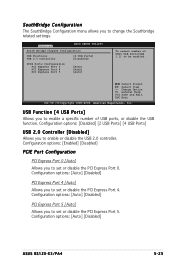
... the PCI Express Port 5. SouthBridge Configuration The SouthBridge Configuration menu allows you to be enabled. Advanced BIOS SETUP UTILITY South Bridge Chipset Configuration USB Functions USB 2.0 Controller [4 USB Ports] [Disabled] PCIE Ports Configuration PCI Express Port 0 PCI Express Port 4...you to enable a specific number of UHCI USB Ports(USB 1.1) to change the Southbridge related settings. Configuration options: [Auto] [Disabled] ASUS RS120-E3/PA4 5-25 USB Function [4 USB Ports] Allows you to set or disable the PCI Express Port 0. Configuration options: [Auto] [Disabled] ...
... the PCI Express Port 5. SouthBridge Configuration The SouthBridge Configuration menu allows you to be enabled. Advanced BIOS SETUP UTILITY South Bridge Chipset Configuration USB Functions USB 2.0 Controller [4 USB Ports] [Disabled] PCIE Ports Configuration PCI Express Port 0 PCI Express Port 4...you to enable a specific number of UHCI USB Ports(USB 1.1) to change the Southbridge related settings. Configuration options: [Auto] [Disabled] ASUS RS120-E3/PA4 5-25 USB Function [4 USB Ports] Allows you to set or disable the PCI Express Port 0. Configuration options: [Auto] [Disabled] ...
User Guide
Page 93
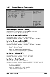
...] [ECP and EPP] Parallel Port IRQ [IRQ7] Allows you to specify the Parallel Port IRQ. Configuration options: [IRQ5] [IRQ7] ASUS RS120-E3/PA4 5-27 5.4.5 Onboard Devices Configuration Advanced BIOS SETUP UTILITY Configure W83627EHF-A Super IO Chipset Onboard Floppy Controller Serial Port1 Address Serial Port2 Address Serial Port2 Mode Parallel Port Address Parallel Port Mode Parallel...
...] [ECP and EPP] Parallel Port IRQ [IRQ7] Allows you to specify the Parallel Port IRQ. Configuration options: [IRQ5] [IRQ7] ASUS RS120-E3/PA4 5-27 5.4.5 Onboard Devices Configuration Advanced BIOS SETUP UTILITY Configure W83627EHF-A Super IO Chipset Onboard Floppy Controller Serial Port1 Address Serial Port2 Address Serial Port2 Mode Parallel Port Address Parallel Port Mode Parallel...