User Guide
Page 5
... Installing hard disk drives 6-3 6.1.3 Setting the RAID item in BIOS 6-3 6.1.4 RAID configuration utility 6-3 6.2 LSI Logic Embedded SATA RAID Setup Utility 6-4 6.2.1 Creating a RAID 0 or RAID 1 set 6-5 6.2.2 Creating a RAID 10 set 6-11 6.2.3 Adding or viewing a RAID configuration 6-15 6.2.4 Initializing the logical drives 6-18 6.2.5 Rebuilding failed drives 6-23 6.2.6 Checking the drives for data consistency 6-25 6.2.7 Deleting a RAID configuration 6-28 6.2.8 Selecting the boot drive from a RAID set 6-29 6.2.9 Enabling the WriteCache 6-30 6.3 Intel® Matrix Storage Manager...
... Installing hard disk drives 6-3 6.1.3 Setting the RAID item in BIOS 6-3 6.1.4 RAID configuration utility 6-3 6.2 LSI Logic Embedded SATA RAID Setup Utility 6-4 6.2.1 Creating a RAID 0 or RAID 1 set 6-5 6.2.2 Creating a RAID 10 set 6-11 6.2.3 Adding or viewing a RAID configuration 6-15 6.2.4 Initializing the logical drives 6-18 6.2.5 Rebuilding failed drives 6-23 6.2.6 Checking the drives for data consistency 6-25 6.2.7 Deleting a RAID configuration 6-28 6.2.8 Selecting the boot drive from a RAID set 6-29 6.2.9 Enabling the WriteCache 6-30 6.3 Intel® Matrix Storage Manager...

User Guide
Page 9
... motherboard layout, jumper settings, and connector locations. 5. ix Chapter 2: Hardware setup This chapter lists the hardware setup procedures that you may refer to when configuring the motherboard. Chapter 6: RAID configuration This chapter tells how to perform when installing or removing system components. 3. Appendix: Reference information This appendix includes additional information that comes with at least basic knowledge of the server, including sections on front panel and rear panel specifications. 2. About this guide...
... motherboard layout, jumper settings, and connector locations. 5. ix Chapter 2: Hardware setup This chapter lists the hardware setup procedures that you may refer to when configuring the motherboard. Chapter 6: RAID configuration This chapter tells how to perform when installing or removing system components. 3. Appendix: Reference information This appendix includes additional information that comes with at least basic knowledge of the server, including sections on front panel and rear panel specifications. 2. About this guide...

User Guide
Page 13
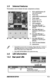
... W power supply, 100V~240V, 50Hz~60Hz Dimensions 600 mm (l) x 445 mm (w) x 43.6 mm (h) *The PCI 33/32 bit slot only use for ASUS® Server Management Board Storage 1 x Ultra ATA 100/66/33 device (slim type optical drive) 4 x SATAII-300 hard disk drive with 8 MB display memory Expansion slots 1 x PCI Express x8 slot (PCI Express 1.0a) 1 x PCI-X 133 MHz/64-bit slot (PCI-X 1.0) 1 x PCI 33 MHz/32-bit/5V slot (PCI 2.3)* 1 x mini-PCI socket for debug card. RAID 0, RAID 1, or RAID 10 configuration using the Intel® Matrix Storage Manager - ASUS RS120-E3/PA4 1-3 1.2 System...
... W power supply, 100V~240V, 50Hz~60Hz Dimensions 600 mm (l) x 445 mm (w) x 43.6 mm (h) *The PCI 33/32 bit slot only use for ASUS® Server Management Board Storage 1 x Ultra ATA 100/66/33 device (slim type optical drive) 4 x SATAII-300 hard disk drive with 8 MB display memory Expansion slots 1 x PCI Express x8 slot (PCI Express 1.0a) 1 x PCI-X 133 MHz/64-bit slot (PCI-X 1.0) 1 x PCI 33 MHz/32-bit/5V slot (PCI 2.3)* 1 x mini-PCI socket for debug card. RAID 0, RAID 1, or RAID 10 configuration using the Intel® Matrix Storage Manager - ASUS RS120-E3/PA4 1-3 1.2 System...
User Guide
Page 15
... 2. Power fans 3. ASUS P5MT-R motherboard 4. Hot-swap HDD tray 1 Connects to SATA4 port (Port3) 12. Hot-swap HDD tray 4 Connects to SATA1 port (Port0) 9. Connect a USB floppy disk drive to any of the USB ports on the front or rear panel if you need to turn off) ASUS RS120-E3/PA4 1-5 LED information 1.6.1 Rear panel LEDs LED Location LED Display status OFF ON Location LED Description Normal status Location switch is pressed (Press the location switch again to use a floppy disk. • Only ASUS CD/DVD-ROMs fit the optical drive bay. 1.5 Internal features The barebone server...
... 2. Power fans 3. ASUS P5MT-R motherboard 4. Hot-swap HDD tray 1 Connects to SATA4 port (Port3) 12. Hot-swap HDD tray 4 Connects to SATA1 port (Port0) 9. Connect a USB floppy disk drive to any of the USB ports on the front or rear panel if you need to turn off) ASUS RS120-E3/PA4 1-5 LED information 1.6.1 Rear panel LEDs LED Location LED Display status OFF ON Location LED Description Normal status Location switch is pressed (Press the location switch again to use a floppy disk. • Only ASUS CD/DVD-ROMs fit the optical drive bay. 1.5 Internal features The barebone server...
User Guide
Page 19
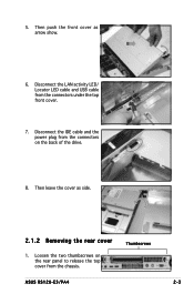
Then leave the cover as arrow show. 6. Thumbscrews ASUS RS120-E3/PA4 2-3 Disconnect the IDE cable and the power plug from the connectors on the rear panel to release the top cover from the connectors under the top front cover. 7. Loosen the two thumbscrews on the back of the drive. 8. 5. Disconnect the LAN activity LED/ Locator LED cable and USB cable from the chassis. Then push the front cover as side. 2.1.2 Removing the rear cover 1.
Then leave the cover as arrow show. 6. Thumbscrews ASUS RS120-E3/PA4 2-3 Disconnect the IDE cable and the power plug from the connectors on the rear panel to release the top cover from the connectors under the top front cover. 7. Loosen the two thumbscrews on the back of the drive. 8. 5. Disconnect the LAN activity LED/ Locator LED cable and USB cable from the chassis. Then push the front cover as side. 2.1.2 Removing the rear cover 1.
User Guide
Page 25
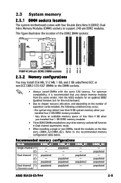
... system memory when you installed four 2 GB DDR2 memory modules - populated populated populated ASUS RS120-E3/PA4 2-9 the system may detect less than 4 GB when you obtain memory modules from the same vendor. Refer to chipset resource allocation, and depending on the blue slots (DIMM_A2/DIMM_B2). populated populated - (3) populated populated populated Dual channel (1) populated populated - (Asymmetric mode) DIMM_B2 - The figure illustrates the location of expansion cards installed...
... system memory when you installed four 2 GB DDR2 memory modules - populated populated populated ASUS RS120-E3/PA4 2-9 the system may detect less than 4 GB when you obtain memory modules from the same vendor. Refer to chipset resource allocation, and depending on the blue slots (DIMM_A2/DIMM_B2). populated populated - (3) populated populated populated Dual channel (1) populated populated - (Asymmetric mode) DIMM_B2 - The figure illustrates the location of expansion cards installed...
User Guide
Page 32
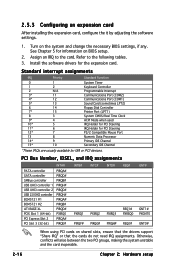
... Interrupt Communications Port (COM2) Communications Port (COM1) Sound Card (sometimes LPT2) Floppy Disk Controller Printer Port (LPT1) System CMOS/Real Time Clock ACPI Mode when used IRQ Holder for PCI Steering IRQ Holder for PCI Steering PS/2 Compatible Mouse Port Numeric Data Processor Primary IDE Channel Secondary IDE Channel *These IRQs are usually available for the expansion card. 2.5.3 Configuring an expansion card After installing the expansion card, configure the it by adjusting the software settings. 1.
... Interrupt Communications Port (COM2) Communications Port (COM1) Sound Card (sometimes LPT2) Floppy Disk Controller Printer Port (LPT1) System CMOS/Real Time Clock ACPI Mode when used IRQ Holder for PCI Steering IRQ Holder for PCI Steering PS/2 Compatible Mouse Port Numeric Data Processor Primary IDE Channel Secondary IDE Channel *These IRQs are usually available for the expansion card. 2.5.3 Configuring an expansion card After installing the expansion card, configure the it by adjusting the software settings. 1.

User Guide
Page 39
ASUS RS120-E3/PA4 2-23 Disconnect all the power cables connected to remove the screws that secure the power supply from the chassis. Slide the power supply forward for about half an inch, then carefully lift it out from the chassis. 4. Use a Phillips (cross) screwdriver to the motherboard and other system devices. 2. 2.8.4 Power supply module To uninstall the power supply module: 1. From the rear panel, remove two screws that secure the front end of the power supply. 3.
ASUS RS120-E3/PA4 2-23 Disconnect all the power cables connected to remove the screws that secure the power supply from the chassis. Slide the power supply forward for about half an inch, then carefully lift it out from the chassis. 4. Use a Phillips (cross) screwdriver to the motherboard and other system devices. 2. 2.8.4 Power supply module To uninstall the power supply module: 1. From the rear panel, remove two screws that secure the front end of the power supply. 3.
User Guide
Page 58
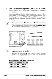
... RAID set using the LSI Logic Embedded SATA RAID utility in the BIOS to the SATA1 or SATA2 connector. Serial ATA connectors (7-pin SATA1, SATA2, SATA3, SATA4) These connectors are set the C o n f i g u r e S A T A A s item in the Intel® ICH7R Southbridge. Serial ATA hard disk drive connection Connector Setting SATA1/SATA3 Master SATA2/SATA4 Slave 4-10 Chapter 4: Motherboard information If you can create a RAID 0, RAID 1, RAID 10, and software RAID 5 configuration using the Intel® Matrix Storage Manager, or RAID 0, RAID 1, and RAID 10 configuration using...
... RAID set using the LSI Logic Embedded SATA RAID utility in the BIOS to the SATA1 or SATA2 connector. Serial ATA connectors (7-pin SATA1, SATA2, SATA3, SATA4) These connectors are set the C o n f i g u r e S A T A A s item in the Intel® ICH7R Southbridge. Serial ATA hard disk drive connection Connector Setting SATA1/SATA3 Master SATA2/SATA4 Slave 4-10 Chapter 4: Motherboard information If you can create a RAID 0, RAID 1, RAID 10, and software RAID 5 configuration using the Intel® Matrix Storage Manager, or RAID 0, RAID 1, and RAID 10 configuration using...
User Guide
Page 81
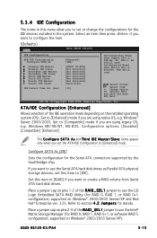
... jumper to use the Intel® Matrix Storage Manager (for RAID 0, RAID 1, RAID 0+1, or software RAID 5 configuration; Set to [Enhanced] mode if you to create a RAID volume from Serial ATA hard disk drives. Set to [Compatible] mode if you want to set or change the configurations for details. supported on Windows® 2000/2003 Server/XP and Red Hat® Enterprise ver. 3.0). Win2000, WIN XP)is used . Set this item to configure the item. (Defaults) Main BIOS SETUP UTILITY IDE Configuration ATA/IDE Configuration Configure SATA...
... jumper to use the Intel® Matrix Storage Manager (for RAID 0, RAID 1, RAID 0+1, or software RAID 5 configuration; Set to [Enhanced] mode if you to create a RAID volume from Serial ATA hard disk drives. Set to [Compatible] mode if you want to set or change the configurations for details. supported on Windows® 2000/2003 Server/XP and Red Hat® Enterprise ver. 3.0). Win2000, WIN XP)is used . Set this item to configure the item. (Defaults) Main BIOS SETUP UTILITY IDE Configuration ATA/IDE Configuration Configure SATA...
User Guide
Page 82
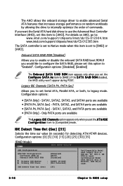
... used . 5-16 Chapter 5: BIOS setup Configuration options: [Disabled] [Enabled] The O n b o a r d S A T A R A I D R O M item appears only when you set the A T A/I D R O M disabled, the RAID utility won't appear during POST. The AHCI allows the onboard storage driver to enable advanced Serial ATA features that increases storage performance on AHCI, go to: www.intel.com/support/chipsets/imst/sb/CS-012304.htm www.intel.com/support/chipsets/imst/sb/CS-012305.htm The SATA controller is set...
... used . 5-16 Chapter 5: BIOS setup Configuration options: [Disabled] [Enabled] The O n b o a r d S A T A R A I D R O M item appears only when you set the A T A/I D R O M disabled, the RAID utility won't appear during POST. The AHCI allows the onboard storage driver to enable advanced Serial ATA features that increases storage performance on AHCI, go to: www.intel.com/support/chipsets/imst/sb/CS-012304.htm www.intel.com/support/chipsets/imst/sb/CS-012305.htm The SATA controller is set...
User Guide
Page 83
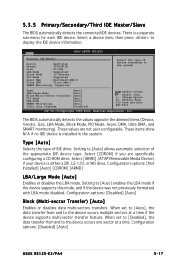
... are not user-configurable. Configuration options: [Not Installed] [Auto] [CDROM] [ARMD] LBA/Large Mode [Auto] Enables or disables the LBA mode. Main BIOS SETUP UTILITY Primary IDE Master Device : Hard Disk Vendor : ST320413A Size : 20.0GB LBA Mode : Supported Block Mode : 16 Sectors PIO Mode : Supported Async DMA : MultiWord DMA-2 Ultra DMA : Ultra DMA-5 SMART Monitoring: Supported Select the type of device connected to [Auto] enables the LBA mode if the device supports this mode, and if the device was not...
... are not user-configurable. Configuration options: [Not Installed] [Auto] [CDROM] [ARMD] LBA/Large Mode [Auto] Enables or disables the LBA mode. Main BIOS SETUP UTILITY Primary IDE Master Device : Hard Disk Vendor : ST320413A Size : 20.0GB LBA Mode : Supported Block Mode : 16 Sectors PIO Mode : Supported Async DMA : MultiWord DMA-2 Ultra DMA : Ultra DMA-5 SMART Monitoring: Supported Select the type of device connected to [Auto] enables the LBA mode if the device supports this mode, and if the device was not...

User Guide
Page 90
... is Disabled. Configuration options: [Auto] [Disabled] 5-24 Chapter 5: BIOS setup When disabled, you can manually set or disable the PCI Express Graphic port. Configuration options: [2 DRAM Clocks] [3 DRAM Clocks] [4 DRAM Clocks] [5 DRAM Clocks] [6 DRAM Clocks] DRAM RAS# Precharge [6 DRAM Clocks] Controls the idle clocks after issuing a precharge command to use as primary boot device. DRAM Frequency [Auto] Allows you to set according to the DRAM SPD (Serial Presence Detect). Configuration options...
... is Disabled. Configuration options: [Auto] [Disabled] 5-24 Chapter 5: BIOS setup When disabled, you can manually set or disable the PCI Express Graphic port. Configuration options: [2 DRAM Clocks] [3 DRAM Clocks] [4 DRAM Clocks] [5 DRAM Clocks] [6 DRAM Clocks] DRAM RAS# Precharge [6 DRAM Clocks] Controls the idle clocks after issuing a precharge command to use as primary boot device. DRAM Frequency [Auto] Allows you to set according to the DRAM SPD (Serial Presence Detect). Configuration options...
User Guide
Page 95
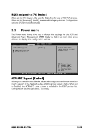
... specific IRQ is free for use of PCI/PnP devices. Configuration options: [Disabled] [Enabled] ASUS RS120-E3/PA4 5-29 Main Advanced Power ACPI APIC Support APM Configuration Hardware Monitor BIOS SETUP UTILITY Boot Exit [Enabled] Include ACPI APIC table pointer to display the configuration options. Change Option F1 General Help F10 Save and Exit ESC Exit v02.58 (C)Copyright 1985-2004, American Megatrends, Inc. ACPI APIC Support [Enabled] Allows you to change the settings for legacy devices. Configuration options: [PCI Device] [Reserved] 5.5 Power menu...
... specific IRQ is free for use of PCI/PnP devices. Configuration options: [Disabled] [Enabled] ASUS RS120-E3/PA4 5-29 Main Advanced Power ACPI APIC Support APM Configuration Hardware Monitor BIOS SETUP UTILITY Boot Exit [Enabled] Include ACPI APIC table pointer to display the configuration options. Change Option F1 General Help F10 Save and Exit ESC Exit v02.58 (C)Copyright 1985-2004, American Megatrends, Inc. ACPI APIC Support [Enabled] Allows you to change the settings for legacy devices. Configuration options: [PCI Device] [Reserved] 5.5 Power menu...

User Guide
Page 96
Configuration options: [Disabled] [Enabled 5-30 Chapter 5: BIOS setup Power Management/APM [Enabled] Allows you to select duty cycle in throttle mode. 5.5.1 APM Configuration Power APM Configuration Power Management/APM Video Power Down Mode Hard Disk Power Down Mode Standby Time Out Suspend Time Out Throttle Slow Clock Ratio System Thermal Power Button Mode Restore on suspend mode. Configuration options: [Disabled] [1 Min] [2 Min] [4 Min] [8 Min] [10 Min] [20 Min] [30 Min] [40 Min] [50 Min] [60 Min] Throttle Slow...
Configuration options: [Disabled] [Enabled 5-30 Chapter 5: BIOS setup Power Management/APM [Enabled] Allows you to select duty cycle in throttle mode. 5.5.1 APM Configuration Power APM Configuration Power Management/APM Video Power Down Mode Hard Disk Power Down Mode Standby Time Out Suspend Time Out Throttle Slow Clock Ratio System Thermal Power Button Mode Restore on suspend mode. Configuration options: [Disabled] [1 Min] [2 Min] [4 Min] [8 Min] [10 Min] [20 Min] [30 Min] [40 Min] [50 Min] [60 Min] Throttle Slow...
User Guide
Page 101
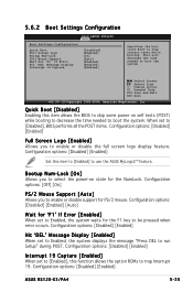
...: [Off] [On] PS/2 Mouse Support [Auto] Allows you to select the power-on self tests (POST) while booting to decrease the time needed to skip certain tests while booting. Configuration options: [Disabled] [Enabled] Hit 'DEL' Message Display [Enabled] When set to [Enabled], this item to [Enabled] to enable or disable support for the F1 key to boot the system. Configuration options: [Disabled] [Enabled] ASUS RS120-E3/PA4 5-35 Configuration options: [Disabled] [Enabled] [Auto] Wait for the NumLock. Change Option F1 General Help...
...: [Off] [On] PS/2 Mouse Support [Auto] Allows you to select the power-on self tests (POST) while booting to decrease the time needed to skip certain tests while booting. Configuration options: [Disabled] [Enabled] Hit 'DEL' Message Display [Enabled] When set to [Enabled], this item to [Enabled] to enable or disable support for the F1 key to boot the system. Configuration options: [Disabled] [Enabled] ASUS RS120-E3/PA4 5-35 Configuration options: [Disabled] [Enabled] [Auto] Wait for the NumLock. Change Option F1 General Help...
User Guide
Page 102
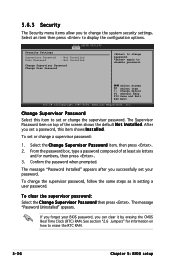
... 5: BIOS setup If you forget your BIOS password, you successfully set your password. The Supervisor Password item on how to disable password. To set or change the supervisor password. To clear the supervisor password: Select the Change Supervisor Password then press . The message "Password Uninstalled" appears. From the password box, type a password composed of the screen shows the default N o t I n s t a l l e d. Confirm the password when prompted. The message "Password Installed" appears after you can clear it by erasing the CMOS...
... 5: BIOS setup If you forget your BIOS password, you successfully set your password. The Supervisor Password item on how to disable password. To set or change the supervisor password. To clear the supervisor password: Select the Change Supervisor Password then press . The message "Password Uninstalled" appears. From the password box, type a password composed of the screen shows the default N o t I n s t a l l e d. Confirm the password when prompted. The message "Password Installed" appears after you can clear it by erasing the CMOS...
User Guide
Page 103
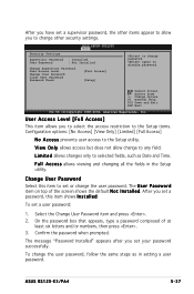
... the Setup items. Configuration options: [No Access] [View Only] [Limited] [Full Access] N o A c c e s s prevents user access to any field. To set your password successfully. F u l l A c c e s s allows viewing and changing all the fields in setting a user password. Select Screen Select Item +- ASUS RS120-E3/PA4 5-37 Confirm the password when prompted. Security Settings BIOS SETUP UTILITY Boot Supervisor Password : Installed User Password : Not Installed Change Supervisor Password User Access Level Change User Password Clear User Password Password Check [Full Access] [Setup] to...
... the Setup items. Configuration options: [No Access] [View Only] [Limited] [Full Access] N o A c c e s s prevents user access to any field. To set your password successfully. F u l l A c c e s s allows viewing and changing all the fields in setting a user password. Select Screen Select Item +- ASUS RS120-E3/PA4 5-37 Confirm the password when prompted. Security Settings BIOS SETUP UTILITY Boot Supervisor Password : Installed User Password : Not Installed Change Supervisor Password User Access Level Change User Password Clear User Password Password Check [Full Access] [Setup] to...
User Guide
Page 108
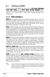
... are not yet configured as a RAID set , copy first the RAID driver from one drive fails, the disk array management software directs all the benefits of both data and parity information across three or more hard disk drives. Use two new drives or use an existing drive and three new drives for this setup. With the RAID 0+1 configuration you install an operating system to the selected hard disk drive. If one drive to a second drive. The new drive must be calculated...
... are not yet configured as a RAID set , copy first the RAID driver from one drive fails, the disk array management software directs all the benefits of both data and parity information across three or more hard disk drives. Use two new drives or use an existing drive and three new drives for this setup. With the RAID 0+1 configuration you install an operating system to the selected hard disk drive. If one drive to a second drive. The new drive must be calculated...
User Guide
Page 109
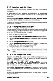
... Main Menu, select IDE Configuration, then press . 3. Save your changes, then exit the BIOS Setup. Refer to section 4.2 Jumpers for details on SATA hard disk drive connection and installation. By default, the SATA hard disk drives are connected to [Enhanced Mode], then press . 4. Refer to sections 1 . 5 I D R O M item to [Enabled]. Otherwise, the RAID configuration utility won't appear during POST. 2. ASUS RS120-E3/PA4 6-3 Use the I D S e t u p U t i l i t y to create a RAID 0, RAID 1, or RAID 0+1 under Windows® 2000/2003 Server/XP operating system. Use the...
... Main Menu, select IDE Configuration, then press . 3. Save your changes, then exit the BIOS Setup. Refer to section 4.2 Jumpers for details on SATA hard disk drive connection and installation. By default, the SATA hard disk drives are connected to [Enhanced Mode], then press . 4. Refer to sections 1 . 5 I D R O M item to [Enabled]. Otherwise, the RAID configuration utility won't appear during POST. 2. ASUS RS120-E3/PA4 6-3 Use the I D S e t u p U t i l i t y to create a RAID 0, RAID 1, or RAID 0+1 under Windows® 2000/2003 Server/XP operating system. Use the...


