
ROG RAMPAGE VI APEX Users ManualEnglish
Page 3
Contents Safety information...vi About this guide...vii RAMPAGE VI APEX specifications summary ix Package contents...xiv Installation tools and components xv Chapter 1: Product Introduction 1.1 Motherboard overview 1-1 1.1.1 Before you proceed 1-1 1.1.2 Motherboard layout 1-2 1.1.3 Central Processing Unit (... 2.1.8 Expansion card installation 2-9 2.1.9 Fan bracket installation 2-10 2.1.10 ROG OC PIN installation 2-12 2.1.11 Wi-Fi antenna installation 2-14 2.2 BIOS update utility 2-15 2.3 Motherboard rear and audio connections 2-16 2.3.1 Rear I/O connection 2-16 2.3.2...
Contents Safety information...vi About this guide...vii RAMPAGE VI APEX specifications summary ix Package contents...xiv Installation tools and components xv Chapter 1: Product Introduction 1.1 Motherboard overview 1-1 1.1.1 Before you proceed 1-1 1.1.2 Motherboard layout 1-2 1.1.3 Central Processing Unit (... 2.1.8 Expansion card installation 2-9 2.1.9 Fan bracket installation 2-10 2.1.10 ROG OC PIN installation 2-12 2.1.11 Wi-Fi antenna installation 2-14 2.2 BIOS update utility 2-15 2.3 Motherboard rear and audio connections 2-16 2.3.1 Rear I/O connection 2-16 2.3.2...

ROG RAMPAGE VI APEX Users ManualEnglish
Page 6
... are not sure about the voltage of the electrical outlet you add a device. • Before connecting or removing signal cables from the motherboard, ensure that all cables are correctly connected and the power cables are connected. Do not place the product in your area. Contact a ... circuits, keep paper clips, screws, and staples away from connectors, slots, sockets and circuitry. • Avoid dust, humidity, and temperature extremes. vi If you encounter technical problems with the product, contact a qualified service technician or your power supply is broken, do not try to fix it ,...
... are not sure about the voltage of the electrical outlet you add a device. • Before connecting or removing signal cables from the motherboard, ensure that all cables are correctly connected and the power cables are connected. Do not place the product in your area. Contact a ... circuits, keep paper clips, screws, and staples away from connectors, slots, sockets and circuitry. • Avoid dust, humidity, and temperature extremes. vi If you encounter technical problems with the product, contact a qualified service technician or your power supply is broken, do not try to fix it ,...

ROG RAMPAGE VI APEX Users ManualEnglish
Page 7
... warranty flyers, that you need when installing and configuring the motherboard. Chapter 3: BIOS Setup This chapter tells how to the following parts: 1. ASUS website The ASUS website (www.asus.com) provides updated information on the motherboard. 2. Optional documentation Your product package may have to perform ... package. It includes description of the switches, jumpers, and connectors on ASUS hardware and software products. 2. Detailed descriptions of the BIOS parameters are not part of the motherboard and the new technology it supports. About this guide is organized This ...
... warranty flyers, that you need when installing and configuring the motherboard. Chapter 3: BIOS Setup This chapter tells how to the following parts: 1. ASUS website The ASUS website (www.asus.com) provides updated information on the motherboard. 2. Optional documentation Your product package may have to perform ... package. It includes description of the switches, jumpers, and connectors on ASUS hardware and software products. 2. Detailed descriptions of the BIOS parameters are not part of the motherboard and the new technology it supports. About this guide is organized This ...

ROG RAMPAGE VI APEX Users ManualEnglish
Page 14
Package contents Check your motherboard package for the following items. Motherboard Cables Accessories Application DVD Documentation ROG RAMPAGE VI APEX 2 x 2-in-1 SATA 6Gb/s cables 2 x DIMM.2 extension card 1 x SLI™ HB Bridge (2-Way L) 1 x SLI™ Bridge (3-Way) 1 x SLI™ Bridge (4-Way) 1 x Extension Cable for RGB Strips (80cm) I/O Shield 1 x Q-Connector 2 x DIMM.2 Fan stand pack 1 x ROG Coaster 1 x ROG R6A MOS FAN Bracket...
Package contents Check your motherboard package for the following items. Motherboard Cables Accessories Application DVD Documentation ROG RAMPAGE VI APEX 2 x 2-in-1 SATA 6Gb/s cables 2 x DIMM.2 extension card 1 x SLI™ HB Bridge (2-Way L) 1 x SLI™ Bridge (3-Way) 1 x SLI™ Bridge (4-Way) 1 x Extension Cable for RGB Strips (80cm) I/O Shield 1 x Q-Connector 2 x DIMM.2 Fan stand pack 1 x ROG Coaster 1 x ROG R6A MOS FAN Bracket...

ROG RAMPAGE VI APEX Users ManualEnglish
Page 15
Installation tools and components Intel® LGA 2066 compatible CPU Fan Intel® LGA 2066 CPU PC chassis SATA hard disk drive Phillips (cross) screwdriver Power supply unit 1 bag of screws DIMM SATA optical disc drive (optional) Graphics card M.2 SSD module (optional) The tools and components in the table above are not included in the motherboard package. xv
Installation tools and components Intel® LGA 2066 compatible CPU Fan Intel® LGA 2066 CPU PC chassis SATA hard disk drive Phillips (cross) screwdriver Power supply unit 1 bag of screws DIMM SATA optical disc drive (optional) Graphics card M.2 SSD module (optional) The tools and components in the table above are not included in the motherboard package. xv

ROG RAMPAGE VI APEX Users ManualEnglish
Page 17
ROG RAMPAGE VI APEX 1-1 Failure to do so may cause severe damage to avoid touching the ICs on them. • Whenever you uninstall any component. • Before handling components, ... Take note of the following precautions before you install or remove any component, ensure that came with the component. • Before you install motherboard components or change any motherboard settings. • Unplug the power cord from the wall socket before touching any component, place it on a grounded antistatic pad or in the...
ROG RAMPAGE VI APEX 1-1 Failure to do so may cause severe damage to avoid touching the ICs on them. • Whenever you uninstall any component. • Before handling components, ... Take note of the following precautions before you install or remove any component, ensure that came with the component. • Before you install motherboard components or change any motherboard settings. • Unplug the power cord from the wall socket before touching any component, place it on a grounded antistatic pad or in the...

ROG RAMPAGE VI APEX Users ManualEnglish
Page 18
1.1.2 Motherboard layout Chapter 1 Refer to 1.1.9 Internal connectors and 2.3.1 Rear I/O connection for more information about rear panel connectors and internal connectors. 1-2 Chapter 1: Product Introduction
1.1.2 Motherboard layout Chapter 1 Refer to 1.1.9 Internal connectors and 2.3.1 Rear I/O connection for more information about rear panel connectors and internal connectors. 1-2 Chapter 1: Product Introduction
ROG RAMPAGE VI APEX Users ManualEnglish
Page 19
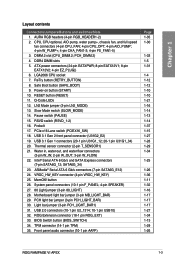
...14 1-37 1-15 1-27 1-28 1-29 1-34 1-25 1-26 1-36 1-11 1-32 1-16 1-17 1-17 1-17 1-27 1-34 1-13 1-29 1-26 ROG RAMPAGE VI APEX 1-3 ATX power connectors (24-pin EATXPWR; 8-pin EATX12V1; 8-pin EATX12V2; 4-pin EZ_PLUG)) 6. ASMedia® Serial ATA 6 Gb/s connectors (7-pin SATA6G_E12) 24. PCH_DIMM... light bar jumper (3-pin PCH_LIGHT_BAR) 30. DIMM.2 slot (CPU_DIMM.2; RSVD switch (RSVD_1-2) 16. LGA2066 CPU socket 7. Motherboard light bar jumper (3-pin MB_LIGHT_BAR) 29. BIOS Switch button (BIOS_SWITCH) 34. Chapter 1 Layout contents Connectors/Jumpers/Buttons and switches/Slots 1.
...14 1-37 1-15 1-27 1-28 1-29 1-34 1-25 1-26 1-36 1-11 1-32 1-16 1-17 1-17 1-17 1-27 1-34 1-13 1-29 1-26 ROG RAMPAGE VI APEX 1-3 ATX power connectors (24-pin EATXPWR; 8-pin EATX12V1; 8-pin EATX12V2; 4-pin EZ_PLUG)) 6. ASMedia® Serial ATA 6 Gb/s connectors (7-pin SATA6G_E12) 24. PCH_DIMM... light bar jumper (3-pin PCH_LIGHT_BAR) 30. DIMM.2 slot (CPU_DIMM.2; RSVD switch (RSVD_1-2) 16. LGA2066 CPU socket 7. Motherboard light bar jumper (3-pin MB_LIGHT_BAR) 29. BIOS Switch button (BIOS_SWITCH) 34. Chapter 1 Layout contents Connectors/Jumpers/Buttons and switches/Slots 1.

ROG RAMPAGE VI APEX Users ManualEnglish
Page 20
.... • Upon purchase of repair only if the damage is shipment/ transit-related. • Keep the cap after installing the motherboard. ASUS will process Return Merchandise Authorization (RMA) requests only if the motherboard comes with a surface mount LGA2066 socket designed for the Intel® Core™ X-series Processors. • Ensure that the PnP...
.... • Upon purchase of repair only if the damage is shipment/ transit-related. • Keep the cap after installing the motherboard. ASUS will process Return Merchandise Authorization (RMA) requests only if the motherboard comes with a surface mount LGA2066 socket designed for the Intel® Core™ X-series Processors. • Ensure that the PnP...

ROG RAMPAGE VI APEX Users ManualEnglish
Page 21
A DDR4 module is notched differently from a DDR, DDR2, or DDR3 module. Chapter 1 1.1.4 System memory The motherboard comes with four DDR4 (Double Data Rate 4) Dual Inline Memory Modules (DIMM) slots. DO NOT install a DDR, DDR2, or DDR3 memory module to the DDR4 slot. Recommended memory configurations ROG RAMPAGE VI APEX 1-5
A DDR4 module is notched differently from a DDR, DDR2, or DDR3 module. Chapter 1 1.1.4 System memory The motherboard comes with four DDR4 (Double Data Rate 4) Dual Inline Memory Modules (DIMM) slots. DO NOT install a DDR, DDR2, or DDR3 memory module to the DDR4 slot. Recommended memory configurations ROG RAMPAGE VI APEX 1-5

ROG RAMPAGE VI APEX Users ManualEnglish
Page 23
Failure to do so may cause you physical injury and damage motherboard components. Chapter 1 Slot No. 1 2 3 4 5 Slot Description PCIE x16/x8_1 slot PCIE x8_2 slot PCIE x4 slot PCIE x16/x8_3 slot PCIE x8_4 slot ROG RAMPAGE VI APEX 1-7 1.1.5 Expansion slots Unplug the power cord before adding or removing expansion cards.
Failure to do so may cause you physical injury and damage motherboard components. Chapter 1 Slot No. 1 2 3 4 5 Slot Description PCIE x16/x8_1 slot PCIE x8_2 slot PCIE x4 slot PCIE x16/x8_3 slot PCIE x8_4 slot ROG RAMPAGE VI APEX 1-7 1.1.5 Expansion slots Unplug the power cord before adding or removing expansion cards.

ROG RAMPAGE VI APEX Users ManualEnglish
Page 26
...1.1.6 Onboard buttons and switches Onboard buttons and switches allow you should shut down the system and unplug the power cable before removing or installing any motherboard component. 2. This is plugged to a power source indicating that you to fine-tune performance when working on a bare or open-case system. The... button also lights up the system. Reset button Press the reset button to enhance system performance. 1. Power-on button The motherboard comes with a power-on button that allows you to power up or wake up when the system is ideal for overclockers and gamers who...
...1.1.6 Onboard buttons and switches Onboard buttons and switches allow you should shut down the system and unplug the power cable before removing or installing any motherboard component. 2. This is plugged to a power source indicating that you to fine-tune performance when working on a bare or open-case system. The... button also lights up the system. Reset button Press the reset button to enhance system performance. 1. Power-on button The motherboard comes with a power-on button that allows you to power up or wake up when the system is ideal for overclockers and gamers who...

ROG RAMPAGE VI APEX Users ManualEnglish
Page 27
Replace the DIMMs with the motherboard may cause system boot failure. function. button Installing DIMMs that you turn ... timing set of failsafe settings. ROG RAMPAGE VI APEX 1-11 If the system fails to test one set of the DRAM_LED. • The DRAM_LED also lights up due to the latest BIOS version from www.asus.com after using the MemOK!...• We recommend that are not compatible with ones recommended in the Memory QVL (Qualified Vendors Lists) at www.asus.com. • If you download and update to BIOS overclocking, press the MemOK! button does not function under ...
Replace the DIMMs with the motherboard may cause system boot failure. function. button Installing DIMMs that you turn ... timing set of failsafe settings. ROG RAMPAGE VI APEX 1-11 If the system fails to test one set of the DRAM_LED. • The DRAM_LED also lights up due to the latest BIOS version from www.asus.com after using the MemOK!...• We recommend that are not compatible with ones recommended in the Memory QVL (Qualified Vendors Lists) at www.asus.com. • If you download and update to BIOS overclocking, press the MemOK! button does not function under ...
ROG RAMPAGE VI APEX Users ManualEnglish
Page 29
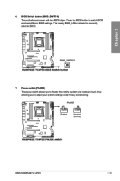
BIOS Switch button (BIOS_SWITCH) The motherboard comes with two BIOS chips. ROG RAMPAGE VI APEX 1-13 The nearby BIOS_LEDs indicate the currently selected BIOS. 7. Chapter 1 6. Pause switch (PAUSE) The pause switch allows you to freeze the cooling system at a hardware level, thus allowing you to switch BIOS and load different BIOS settings. Press the BIOS button to adjust your system settings under heavy overclocking.
BIOS Switch button (BIOS_SWITCH) The motherboard comes with two BIOS chips. ROG RAMPAGE VI APEX 1-13 The nearby BIOS_LEDs indicate the currently selected BIOS. 7. Chapter 1 6. Pause switch (PAUSE) The pause switch allows you to freeze the cooling system at a hardware level, thus allowing you to switch BIOS and load different BIOS settings. Press the BIOS button to adjust your system settings under heavy overclocking.

ROG RAMPAGE VI APEX Users ManualEnglish
Page 32
Chapter 1 1.1.7 Jumpers 1. LN2 Mode jumper (3-pin LN2_MODE) With LN2 mode activated, the ROG motherboard is optimized to remedy the cold-boot bug during POST and help the system boot successfully. 2. 80 light jumper (3-pin 80_LIGHT) This jumper allows you to enable or disable the onboard Q-CODE LED. 1-16 Chapter 1: Product Introduction
Chapter 1 1.1.7 Jumpers 1. LN2 Mode jumper (3-pin LN2_MODE) With LN2 mode activated, the ROG motherboard is optimized to remedy the cold-boot bug during POST and help the system boot successfully. 2. 80 light jumper (3-pin 80_LIGHT) This jumper allows you to enable or disable the onboard Q-CODE LED. 1-16 Chapter 1: Product Introduction

ROG RAMPAGE VI APEX Users ManualEnglish
Page 33
Motherboard light bar jumper (3-pin MB_LIGHT_BAR) This jumper allows you to enable and disable the motherboard back light. 4. Chapter 1 3. ROG RAMPAGE VI APEX 1-17 PCH light bar jumper (3-pin PCH_LIGHT_BAR) This jumper allows you to enable or disable the onboard PCH and light bar 2 LED .
Motherboard light bar jumper (3-pin MB_LIGHT_BAR) This jumper allows you to enable and disable the motherboard back light. 4. Chapter 1 3. ROG RAMPAGE VI APEX 1-17 PCH light bar jumper (3-pin PCH_LIGHT_BAR) This jumper allows you to enable or disable the onboard PCH and light bar 2 LED .
ROG RAMPAGE VI APEX Users ManualEnglish
Page 35
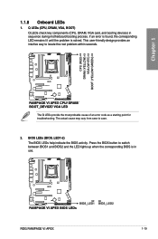
... for troubleshooting. The actual cause may vary from case to locate the root problem within seconds. ROG RAMPAGE VI APEX 1-19 If an error is found, the corresponding LED remains lit until the problem is in sequence during motherboard booting process. Press the BIOS button to switch between BIOS1 and BIOS2 and the LED lights...
... for troubleshooting. The actual cause may vary from case to locate the root problem within seconds. ROG RAMPAGE VI APEX 1-19 If an error is found, the corresponding LED remains lit until the problem is in sequence during motherboard booting process. Press the BIOS button to switch between BIOS1 and BIOS2 and the LED lights...

ROG RAMPAGE VI APEX Users ManualEnglish
Page 36
DIMM LED (DIMM_A_LED; Hard Disk LED (HD_LED) The Hard Disk LED is enabled. 4. DIMM_D_LED) The DIMM LED indicates when the corresponding memory channel is designed to the motherboard or when the hard disk drive does not function. 1-20 Chapter 1: Product Introduction It blinks when data is no hard disk drive connected to indicate the hard disk activity. DIMM_B_LED; The LED does not light up when there is being written into or read from the hard disk drive. DIMM_C_LED; Chapter 1 3.
DIMM LED (DIMM_A_LED; Hard Disk LED (HD_LED) The Hard Disk LED is enabled. 4. DIMM_D_LED) The DIMM LED indicates when the corresponding memory channel is designed to the motherboard or when the hard disk drive does not function. 1-20 Chapter 1: Product Introduction It blinks when data is no hard disk drive connected to indicate the hard disk activity. DIMM_B_LED; The LED does not light up when there is being written into or read from the hard disk drive. DIMM_C_LED; Chapter 1 3.

ROG RAMPAGE VI APEX Users ManualEnglish
Page 42
... panel audio I /O module cable to this connector to Serial ATA 6 Gb/s hard disk drives via Serial ATA 6 Gb/s signal cables. Connect one end of the motherboard's high-definition audio capability. 1-26 Chapter 1: Product Introduction
... panel audio I /O module cable to this connector to Serial ATA 6 Gb/s hard disk drives via Serial ATA 6 Gb/s signal cables. Connect one end of the motherboard's high-definition audio capability. 1-26 Chapter 1: Product Introduction

ROG RAMPAGE VI APEX Users ManualEnglish
Page 45
...that monitor the temperature of the devices and the critical components inside the motherboard. Connect the thermistor cable and place the sensor on the device or the motherboard's component to detect its temperature. 8. TPM connector (14-1 pin TPM...) This connector supports a Trusted Platform Module (TPM) system, which securely stores keys, digital certificates, passwords and data. A TPM system also helps enhance network security, protect digital identities, and ensures platform integrity. ROG RAMPAGE VI APEX...
...that monitor the temperature of the devices and the critical components inside the motherboard. Connect the thermistor cable and place the sensor on the device or the motherboard's component to detect its temperature. 8. TPM connector (14-1 pin TPM...) This connector supports a Trusted Platform Module (TPM) system, which securely stores keys, digital certificates, passwords and data. A TPM system also helps enhance network security, protect digital identities, and ensures platform integrity. ROG RAMPAGE VI APEX...


