
Pundit Manual
Page 7
Chapter 5: Motherboard Information This chapter gives information about the ASUS Book Size Barebone System. Chapter 7: Starting up This chapter helps you power up your system and install drivers and utilities that came with the... This chapter gives a general description of the BIOS parameters. 7. It includes detailed descriptions of the ASUS book size barebone system. How this guide Audience This guide provides general information and installation instructions about the P4S8L motherboard that can be included in installing other optional components that came with the system.This...
Chapter 5: Motherboard Information This chapter gives information about the ASUS Book Size Barebone System. Chapter 7: Starting up This chapter helps you power up your system and install drivers and utilities that came with the... This chapter gives a general description of the BIOS parameters. 7. It includes detailed descriptions of the ASUS book size barebone system. How this guide Audience This guide provides general information and installation instructions about the P4S8L motherboard that can be included in installing other optional components that came with the system.This...

Pundit Manual
Page 15
ASUS has designed the Pundit for an ASUS P4S8L motherboard only. System Assembly Chapter 2 Step-by ASUS, make sure that it fits into the case and the I/O connectors correspond to the openings on how to install other than the original supplied by -step instructions on the back panel. Before installing any motherboard other motherboards. ASUS Book Size Barebone System 2-1 It is not advisable to install basic components.
ASUS has designed the Pundit for an ASUS P4S8L motherboard only. System Assembly Chapter 2 Step-by ASUS, make sure that it fits into the case and the I/O connectors correspond to the openings on how to install other than the original supplied by -step instructions on the back panel. Before installing any motherboard other motherboards. ASUS Book Size Barebone System 2-1 It is not advisable to install basic components.

Pundit Manual
Page 19
DO NOT force a DIMM into a socket to insert the three plastic tabs without stress. P4S8L ® P4S8L 184-Pin DDR DIMM Sockets 80 Pins 104 Pins A DDR DIMM is properly seated. 6. Unlock a DIMM socket by pressing the retaining clips outward. 4. take care ... the DIMM is keyed with a notch so that the notch on the DIMM matches the break on the ASUS motherboard. Firmly insert the DIMM into its original position. Then, replace the front bezel; ASUS Book Size Barebone System 2-5 2.3 Installing the system memory 1. To perform this procedure, make sure 2 Locate the two DDR...
DO NOT force a DIMM into a socket to insert the three plastic tabs without stress. P4S8L ® P4S8L 184-Pin DDR DIMM Sockets 80 Pins 104 Pins A DDR DIMM is properly seated. 6. Unlock a DIMM socket by pressing the retaining clips outward. 4. take care ... the DIMM is keyed with a notch so that the notch on the DIMM matches the break on the ASUS motherboard. Firmly insert the DIMM into its original position. Then, replace the front bezel; ASUS Book Size Barebone System 2-5 2.3 Installing the system memory 1. To perform this procedure, make sure 2 Locate the two DDR...

Pundit Manual
Page 20
2.4 Installing the CPU 1. Press down and unhook the metal retaining clips on the motherboard. Lift the heatsink assembly up and out. 5. Locate the CPU Socket 478 on both sides of the metal heatsink. 3. Pundit P4S8L Motherboard 2-6 Chapter 2: System Assemby To install the CPU, it is necessary to remove the pre-installed heatsink assembly. 2. Disconnect the CPU fan power cable if it is too short. 4.
2.4 Installing the CPU 1. Press down and unhook the metal retaining clips on the motherboard. Lift the heatsink assembly up and out. 5. Locate the CPU Socket 478 on both sides of the metal heatsink. 3. Pundit P4S8L Motherboard 2-6 Chapter 2: System Assemby To install the CPU, it is necessary to remove the pre-installed heatsink assembly. 2. Disconnect the CPU fan power cable if it is too short. 4.

Pundit Manual
Page 37
... layout, jumper settings, and connector locations. It is designed to supports the ASUS P4S8L motherboard. Chapter 5 This chapter gives information about the ASUS P4S8L motherboard that the I/O connectors corresponds to the openings of the front and rear panels. Motherboard Info IMPORTANT The ASUS Pundit barebone system is not recommended to install other motherboard model and sizes...
... layout, jumper settings, and connector locations. It is designed to supports the ASUS P4S8L motherboard. Chapter 5 This chapter gives information about the ASUS P4S8L motherboard that the I/O connectors corresponds to the openings of the front and rear panels. Motherboard Info IMPORTANT The ASUS Pundit barebone system is not recommended to install other motherboard model and sizes...

Pundit Manual
Page 42
... a metal object, such as the power supply case, before touching any component, ensure that came with a surface mount 478-pin Zero Insertion Force (ZIF) socket. P4S8L ® P4S8L Socket 478 5-6 Gold Arrow Chapter 5: Motherboard Information Whenever you install or remove any component. 2. Use a grounded wrist strap or touch a safely grounded object or...
... a metal object, such as the power supply case, before touching any component, ensure that came with a surface mount 478-pin Zero Insertion Force (ZIF) socket. P4S8L ® P4S8L Socket 478 5-6 Gold Arrow Chapter 5: Motherboard Information Whenever you install or remove any component. 2. Use a grounded wrist strap or touch a safely grounded object or...

Pundit Manual
Page 43
... to the 168-pin of the SDR DIMM. Install the software drivers for the expansion card. P4S8L ® P4S8L 184-Pin DDR DIMM Sockets 80 Pins 104 Pins 5.6 Expansion slots The P4S8L motherboard has three (3) expansion slots. ASUS Book Size Barebone System 5-7 Assign an IRQ to the tables below. 3. Turn on the system and...
... to the 168-pin of the SDR DIMM. Install the software drivers for the expansion card. P4S8L ® P4S8L 184-Pin DDR DIMM Sockets 80 Pins 104 Pins 5.6 Expansion slots The P4S8L motherboard has three (3) expansion slots. ASUS Book Size Barebone System 5-7 Assign an IRQ to the tables below. 3. Turn on the system and...

Pundit Manual
Page 45
... wake up the computer from S3 sleep mode (no power to the front USB ports. P4S8L ® P4S8L USB Device Wake Up USBPWR56 12 23 +5V (Default) +5VSB USBPWR12 2 1 +5V (Default) 3 2 +5VSB USBPWR34 21 32 +5V (Default) +5VSB ASUS Book Size Barebone System 5-9 Both jumpers are for the internal USB header that can...
... wake up the computer from S3 sleep mode (no power to the front USB ports. P4S8L ® P4S8L USB Device Wake Up USBPWR56 12 23 +5V (Default) +5VSB USBPWR12 2 1 +5V (Default) 3 2 +5VSB USBPWR34 21 32 +5V (Default) +5VSB ASUS Book Size Barebone System 5-9 Both jumpers are for the internal USB header that can...

Pundit Manual
Page 46
... and enter BIOS setup to clear CMOS. 4. The RAM data in CMOS. To erase the RTC RAM: 1. CMOS_CLR1 12 23 Normal Clear CMOS (Default) P4S8L ® P4S8L Clear RTC RAM 5-10 Chapter 5: Motherboard Information Reinstall the battery. 5. Short the solder points to re-enter data. You can clear the CMOS memory of...
... and enter BIOS setup to clear CMOS. 4. The RAM data in CMOS. To erase the RTC RAM: 1. CMOS_CLR1 12 23 Normal Clear CMOS (Default) P4S8L ® P4S8L Clear RTC RAM 5-10 Chapter 5: Motherboard Information Reinstall the battery. 5. Short the solder points to re-enter data. You can clear the CMOS memory of...

Pundit Manual
Page 47
...+2.5 Dual voltage setting. Set to the DDR DIMMs. It is recommended that you keep the default setting (+2.5 Dual) P4S8L ® OVSEL1 21 32 OVER Voltage +2.5_DUAL P4S8L OVER Voltage Setting(OVSEL1) (Default) 3. Over Voltage Setting 1(2-pin OVSEL1) This jumper allows you to pins 1-2 for... you to the CPU. 2. It is recommended that you keep the default setting (VCORE) P4S8L ® OVSEL2 21 32 OVER Voltage VCORE P4S8L OVER Voltage Setting(OVSEL2) (Default) ASUS Book Size Barebone System 5-11 Setting to a high voltage may cause permanent damage to set the...
...+2.5 Dual voltage setting. Set to the DDR DIMMs. It is recommended that you keep the default setting (+2.5 Dual) P4S8L ® OVSEL1 21 32 OVER Voltage +2.5_DUAL P4S8L OVER Voltage Setting(OVSEL1) (Default) 3. Over Voltage Setting 1(2-pin OVSEL1) This jumper allows you to pins 1-2 for... you to the CPU. 2. It is recommended that you keep the default setting (VCORE) P4S8L ® OVSEL2 21 32 OVER Voltage VCORE P4S8L OVER Voltage Setting(OVSEL2) (Default) ASUS Book Size Barebone System 5-11 Setting to a high voltage may cause permanent damage to set the...

Pundit Manual
Page 48
... two UltraDMA/133/100/66 devices, purchase another for the jumper settings. For UltraDMA/133/100/66 IDE devices, use an 80-conductor IDE cable. P4S8L ® P4S8L IDE Connectors PRI_IDE NOTE: Orient the red markings (usually zigzag) on the UltraDMA cable connector. BIOS supports specific device bootup. 5.8 Connectors This section describes...
... two UltraDMA/133/100/66 devices, purchase another for the jumper settings. For UltraDMA/133/100/66 IDE devices, use an 80-conductor IDE cable. P4S8L ® P4S8L IDE Connectors PRI_IDE NOTE: Orient the red markings (usually zigzag) on the UltraDMA cable connector. BIOS supports specific device bootup. 5.8 Connectors This section describes...

Pundit Manual
Page 49
... panel of the chassis. ATXPWR1 +3.3VDC +3.3VDC GND +5.0VDC GND +5.0VDC GND PWR_OK +5VSB +12.0VDC P4S8L ® +3.3VDC -12.0VDC GND PS_ON# GND GND GND -5.0VDC +5.0VDC +5.0VDC P4S8L Floppy ATX Power Connectors ATX12V1 GND +12V DC GND +12V DC If you will need to an ATX 12V...the power supply is 230W, or 300W for a fully configured system. Find the proper orientation and push down firmly until the connectors completely fit. ASUS Book Size Barebone System 5-13 ATX power connectors (20-pin ATXPWR1, 4-pin ATX12V1) These connectors connect to replace the power supply in the future,...
... panel of the chassis. ATXPWR1 +3.3VDC +3.3VDC GND +5.0VDC GND +5.0VDC GND PWR_OK +5VSB +12.0VDC P4S8L ® +3.3VDC -12.0VDC GND PS_ON# GND GND GND -5.0VDC +5.0VDC +5.0VDC P4S8L Floppy ATX Power Connectors ATX12V1 GND +12V DC GND +12V DC If you will need to an ATX 12V...the power supply is 230W, or 300W for a fully configured system. Find the proper orientation and push down firmly until the connectors completely fit. ASUS Book Size Barebone System 5-13 ATX power connectors (20-pin ATXPWR1, 4-pin ATX12V1) These connectors connect to replace the power supply in the future,...

Pundit Manual
Page 50
...headers (10-1 pin USB56) USBPWR56 is for the internal USB header that the heat sink fins allow air flow to the front USB ports. P4S8L ® P4S8L 12-Volt Cooling Fan Power CPU_FAN1 GND +12V Rotation CHA_FAN1 Rotation +12V GND Do not forget to connect the fan cables to the ground pin... fan connectors! 5-14 Chapter 5: Motherboard Information The fan wiring and plug may damage the motherboard components. Lack of 1A (12W) at +12V. USBP3+ GND P4S8L USB Ports 5. Connect the fan cable to the connector matching the black wire to the fan connectors. USBP2+ GND NC 1 5 USB56 6 10...
...headers (10-1 pin USB56) USBPWR56 is for the internal USB header that the heat sink fins allow air flow to the front USB ports. P4S8L ® P4S8L 12-Volt Cooling Fan Power CPU_FAN1 GND +12V Rotation CHA_FAN1 Rotation +12V GND Do not forget to connect the fan cables to the ground pin... fan connectors! 5-14 Chapter 5: Motherboard Information The fan wiring and plug may damage the motherboard components. Lack of 1A (12W) at +12V. USBP3+ GND P4S8L USB Ports 5. Connect the fan cable to the connector matching the black wire to the fan connectors. USBP2+ GND NC 1 5 USB56 6 10...

Pundit Manual
Page 51
OnBoard LED This Light Emitting Diode (LED) lights-ON if there is standby power and lights-OFF when the power is turned off. SBPWRLED1 ON OFF Standby Powered P4S8L Power Off ® P4S8L Onboard LED ASUS Book Size Barebone System 5-15 6. Internal audio connectors (4-pin CD1) These connectors allow you to receive stereo audio input from sound sources such as a CD-ROM, TV tuner, or MPEG card. Left Audio Channel Ground Right Audio Channel P4S8L ® P4S8L Internal Audio Connectors CD1(Black) 7.
OnBoard LED This Light Emitting Diode (LED) lights-ON if there is standby power and lights-OFF when the power is turned off. SBPWRLED1 ON OFF Standby Powered P4S8L Power Off ® P4S8L Onboard LED ASUS Book Size Barebone System 5-15 6. Internal audio connectors (4-pin CD1) These connectors allow you to receive stereo audio input from sound sources such as a CD-ROM, TV tuner, or MPEG card. Left Audio Channel Ground Right Audio Channel P4S8L ® P4S8L Internal Audio Connectors CD1(Black) 7.

Pundit Manual
Page 52
TV out connector This 10-1 pin connector connects to the front panel system power and IDE LEDs. TVOUT_REARAUDIO1 P4S8L ® P4S8L TVOUT_REARAUDIO Connectors ® D33005 5-16 Chapter 5: Motherboard Information LED connector (6-pin LED_CON1) This 6-pin connector connects to the front panel daughter card with the audio and tv-out ports. PLED+ NC IDE_LED+ P4S8L ® P4S8L LED Connector 9. LED_CON1 PLEDNC IDE_LED- 8.
TV out connector This 10-1 pin connector connects to the front panel system power and IDE LEDs. TVOUT_REARAUDIO1 P4S8L ® P4S8L TVOUT_REARAUDIO Connectors ® D33005 5-16 Chapter 5: Motherboard Information LED connector (6-pin LED_CON1) This 6-pin connector connects to the front panel daughter card with the audio and tv-out ports. PLED+ NC IDE_LED+ P4S8L ® P4S8L LED Connector 9. LED_CON1 PLEDNC IDE_LED- 8.

Pundit Manual
Page 53
BIOS Information ASUS Book Size Barebone System 6-1 Chapter 6 This chapter gives information about the ASUS P4S8L Basic Input/Output System (BIOS).This chapter includes updating the BIOS using the ASUS AFLASH BIOS utility that is bundled with the support CD.
BIOS Information ASUS Book Size Barebone System 6-1 Chapter 6 This chapter gives information about the ASUS P4S8L Basic Input/Output System (BIOS).This chapter includes updating the BIOS using the ASUS AFLASH BIOS utility that is bundled with the support CD.
Pundit Manual
Page 54
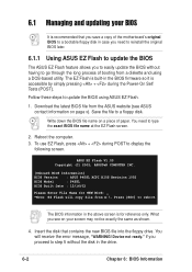
...file to type the exact BIOS file name at the EZ Flash screen. 2. You will copy file from a diskette and using ASUS EZ Flash. 1. if you see ASUS contact information on a piece of booting from A:\, Press [ESC] to go through the long process of paper. Write down the... simply pressing + during POST to update the BIOS using a DOS-based utility. ASUS EZ Flash V1.00 Copyright (C) 2002, ASUSTeK COMPUTER INC. [Onboard BIOS Information] BIOS Version : ASUS P4S8L ACPI BIOS Revision 1002 BIOS Model : P4S8L BIOS Built Date : 12/16/02 Please Enter File Name for reference only. ...
...file to type the exact BIOS file name at the EZ Flash screen. 2. You will copy file from a diskette and using ASUS EZ Flash. 1. if you see ASUS contact information on a piece of booting from A:\, Press [ESC] to go through the long process of paper. Write down the... simply pressing + during POST to update the BIOS using a DOS-based utility. ASUS EZ Flash V1.00 Copyright (C) 2002, ASUSTeK COMPUTER INC. [Onboard BIOS Information] BIOS Version : ASUS P4S8L ACPI BIOS Revision 1002 BIOS Model : P4S8L BIOS Built Date : 12/16/02 Please Enter File Name for reference only. ...
Pundit Manual
Page 55
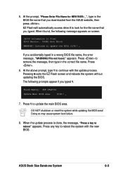
...with the update process. Press any key to remove the message, then type in File] BIOS Version: P4S8L Boot Block WARNING! Pressing N exits the EZ Flash screen and reboots the system without updating the BIOS. ASUS Book Size Barebone System 6-3 EZ Flash will automatically access drive A to update the BIOS (Y/N)? _ ...If you downloaded from the ASUS website, then press . When the update process is done, the message, "Press a key to update the main BIOS area. At the prompt, "Please...
...with the update process. Press any key to remove the message, then type in File] BIOS Version: P4S8L Boot Block WARNING! Pressing N exits the EZ Flash screen and reboots the system without updating the BIOS. ASUS Book Size Barebone System 6-3 EZ Flash will automatically access drive A to update the BIOS (Y/N)? _ ...If you downloaded from the ASUS website, then press . When the update process is done, the message, "Press a key to update the main BIOS area. At the prompt, "Please...

Pundit Manual
Page 92
... CD that came with the motherboard contains useful software and several utility drivers that enhance the motherboard features. Visit the ASUS website for general reference only. 7.1 Install an operating system The P4S8L motherboard supports Windows 98/ME/NT/2000/XP operating systems (OS). The contents of your CD-ROM drive. If Autorun...
... CD that came with the motherboard contains useful software and several utility drivers that enhance the motherboard features. Visit the ASUS website for general reference only. 7.1 Install an operating system The P4S8L motherboard supports Windows 98/ME/NT/2000/XP operating systems (OS). The contents of your CD-ROM drive. If Autorun...

Pundit Manual
Page 94
... CLICK THE LEFT ARROW TO RETURN TO THE MAIN MENU 7-4 Chapter 7: Starting Up Browse Support CD Click this item to exit the P4S8L support CD. ASUS PC Probe This smart utility monitors the fan speed, CPU temperature, and system voltages, and alerts you on any detected problems. This ...ADOBE Acrobat Reader V5.0 This item installs the ADOBE Acrobat Reader version 5.0. Exit Click this item to display the general specifications for the P4S8L motherboard. Show Motherboard Information Click this item to display the support CD contents in text format. CLICK THE RIGHT ARROW TO SEE THE NEXT...
... CLICK THE LEFT ARROW TO RETURN TO THE MAIN MENU 7-4 Chapter 7: Starting Up Browse Support CD Click this item to exit the P4S8L support CD. ASUS PC Probe This smart utility monitors the fan speed, CPU temperature, and system voltages, and alerts you on any detected problems. This ...ADOBE Acrobat Reader V5.0 This item installs the ADOBE Acrobat Reader version 5.0. Exit Click this item to display the general specifications for the P4S8L motherboard. Show Motherboard Information Click this item to display the support CD contents in text format. CLICK THE RIGHT ARROW TO SEE THE NEXT...