
Manual pdf format file for PU-DLS/PU-DL M/B
Page 8
... following parts: • Chapter 1: Product introduction This chapter describes the features of the PU-DLS/PU-DL motherboard. It includes description of the BIOS parameters are also provided. • Chapter 5: Driver Installation This chapter tells how to change ...PU-DLS model only), LAN, and audio drivers for various operating systems. viii It includes brief descriptions of the special attributes of the motherboard and the new technology it supports. • Chapter 2: Hardware information This chapter lists the hardware setup procedures that you need when installing the ASUS PU-DLS/PU-DL...
... following parts: • Chapter 1: Product introduction This chapter describes the features of the PU-DLS/PU-DL motherboard. It includes description of the BIOS parameters are also provided. • Chapter 5: Driver Installation This chapter tells how to change ...PU-DLS model only), LAN, and audio drivers for various operating systems. viii It includes brief descriptions of the special attributes of the motherboard and the new technology it supports. • Chapter 2: Hardware information This chapter lists the hardware setup procedures that you need when installing the ASUS PU-DLS/PU-DL...

Manual pdf format file for PU-DLS/PU-DL M/B
Page 12
PU-DLS/PU-DL specifications summary BIOS features Form Factor Support CD contents 4Mb Firmware Hub (FWH), Award BIOS with ACPI, DMI, Green, PnP features, and Enhanced Server BIOS features Extended ATX form factor: 12 in x 13 in (30.5 cm x 33 cm) Device drivers Management software Utilities Contact information xii
PU-DLS/PU-DL specifications summary BIOS features Form Factor Support CD contents 4Mb Firmware Hub (FWH), Award BIOS with ACPI, DMI, Green, PnP features, and Enhanced Server BIOS features Extended ATX form factor: 12 in x 13 in (30.5 cm x 33 cm) Device drivers Management software Utilities Contact information xii
Manual pdf format file for PU-DLS/PU-DL M/B
Page 19
...PU-DLS BIOS setup. The SCSI boot selection is available only on the following high-level goals: support for Plug-and-Play compatibility and power management for configuring and managing all system components, 32-bit device drivers, and installation procedures for SDG 2.0 certification. ASUS PU-DLS/PU-DL... motherboard user guide 1-5 Color-coded connectors and descriptive icons make identification easy as required by the PC '99 specification. Compliance Both the BIOS and the hardware levels of the motherboard meet ...
...PU-DLS BIOS setup. The SCSI boot selection is available only on the following high-level goals: support for Plug-and-Play compatibility and power management for configuring and managing all system components, 32-bit device drivers, and installation procedures for SDG 2.0 certification. ASUS PU-DLS/PU-DL... motherboard user guide 1-5 Color-coded connectors and descriptive icons make identification easy as required by the PC '99 specification. Compliance Both the BIOS and the hardware levels of the motherboard meet ...
Manual pdf format file for PU-DLS/PU-DL M/B
Page 23
...multiple system functions that the CPUs installed on the motherboard, and serves as a reminder to prevent incorrect insertion of item 7.) 13 ASUS ASIC. ASUS PU-DLS/PU-DL motherboard user guide 1-9 9 Firmware hub. This LED does not light up if there is only one parallel port with EPP and... Hub 3 (ICH3-S) provides the legacy I/O subsystem and integrates various I /O functionality. This 4Mb firmware hub (FWH) contains the programmable BIOS program. 10 IDE connectors. These dual-channel bus master IDE connectors support up if there is slotted to the MCH, dualchannel Ultra ATA/...
...multiple system functions that the CPUs installed on the motherboard, and serves as a reminder to prevent incorrect insertion of item 7.) 13 ASUS ASIC. ASUS PU-DLS/PU-DL motherboard user guide 1-9 9 Firmware hub. This LED does not light up if there is only one parallel port with EPP and... Hub 3 (ICH3-S) provides the legacy I/O subsystem and integrates various I /O functionality. This 4Mb firmware hub (FWH) contains the programmable BIOS program. 10 IDE connectors. These dual-channel bus master IDE connectors support up if there is slotted to the MCH, dualchannel Ultra ATA/...
Manual pdf format file for PU-DLS/PU-DL M/B
Page 37
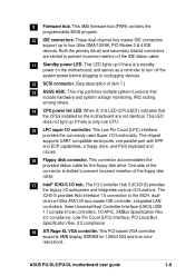
...an IRQ to the tables on the slot. 5. Install the software drivers for information on the system and change the necessary BIOS settings, if any. ASUS PU-DLS/PU-DL motherboard user guide 2-11 Remove the bracket opposite the slot that they support. Align the card connector with the screw you... installing the expansion card, configure the it and make the necessary hardware settings for later use . Refer to the card. Turn on BIOS setup. 2. See Chapter 4 for the expansion card. Make sure to install expansion cards. Failure to install an expansion card. 1. ...
...an IRQ to the tables on the slot. 5. Install the software drivers for information on the system and change the necessary BIOS settings, if any. ASUS PU-DLS/PU-DL motherboard user guide 2-11 Remove the bracket opposite the slot that they support. Align the card connector with the screw you... installing the expansion card, configure the it and make the necessary hardware settings for later use . Refer to the card. Turn on BIOS setup. 2. See Chapter 4 for the expansion card. Make sure to install expansion cards. Failure to install an expansion card. 1. ...
Manual pdf format file for PU-DLS/PU-DL M/B
Page 43
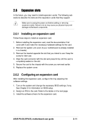
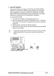
...pins 1-2. Keep the cap on CLRTC jumper default position. Removing the cap will cause system boot failure! ® PU-DLS PU-DLS Clear RTC RAM J3 12 23 Clear CMOS Normal (Default) ASUS PU-DLS/PU-DL motherboard user guide 2-17 7. Turn OFF the computer and unplug the power cord. 2. Except when clearing the RTC... memory of date, time, and system setup parameters by the onboard button cell battery. Hold down the key during the boot process and enter BIOS setup to pins 2-3. 3. The RAM data in CMOS. Move the jumper cap from pins 2-3 (default) to clear the Real Time Clock ...
...pins 1-2. Keep the cap on CLRTC jumper default position. Removing the cap will cause system boot failure! ® PU-DLS PU-DLS Clear RTC RAM J3 12 23 Clear CMOS Normal (Default) ASUS PU-DLS/PU-DL motherboard user guide 2-17 7. Turn OFF the computer and unplug the power cord. 2. Except when clearing the RTC... memory of date, time, and system setup parameters by the onboard button cell battery. Hold down the key during the boot process and enter BIOS setup to pins 2-3. 3. The RAM data in CMOS. Move the jumper cap from pins 2-3 (default) to clear the Real Time Clock ...
Manual pdf format file for PU-DLS/PU-DL M/B
Page 45
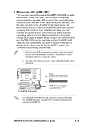
... the cables. 2. This prevents incorrect orientation when you must configure the second drive as a slave device by setting its jumper accordingly. ASUS PU-DLS/PU-DL motherboard user guide 2-19 Connect the cable's blue connector to the primary (recommended) or secondary IDE connector, then connect the gray connector... cables - IDE connectors (40-1 pin IDE1, IDE2) This connector supports the provided UltraDMA/100/66 IDE hard disk ribbon cable. BIOS supports specific device bootup. It is removed to the hard disk documentation for the secondary IDE connector. 1. Refer to match the covered...
... the cables. 2. This prevents incorrect orientation when you must configure the second drive as a slave device by setting its jumper accordingly. ASUS PU-DLS/PU-DL motherboard user guide 2-19 Connect the cable's blue connector to the primary (recommended) or secondary IDE connector, then connect the gray connector... cables - IDE connectors (40-1 pin IDE1, IDE2) This connector supports the provided UltraDMA/100/66 IDE hard disk ribbon cable. BIOS supports specific device bootup. It is removed to the hard disk documentation for the secondary IDE connector. 1. Refer to match the covered...
Manual pdf format file for PU-DLS/PU-DL M/B
Page 55
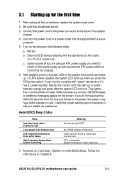
... seconds from the time you press the ATX power switch. At power on the devices in Chapter 4. ASUS PU-DLS/PU-DL motherboard user guide 3-1 3.1 Starting up for assistance. Connect the power cord to enter BIOS Setup. Monitor b. After applying power, the power LED on tests. The system then runs the power-... not found or video card memory bad CPU overheated; Turn on , hold down to the power connector at a lower frequency 7. Award BIOS Beep Codes Beep One short beep when displaying logo Long beeps in an endless loop One long beep followed by three short beeps High frequency...
... seconds from the time you press the ATX power switch. At power on the devices in Chapter 4. ASUS PU-DLS/PU-DL motherboard user guide 3-1 3.1 Starting up for assistance. Connect the power cord to enter BIOS Setup. Monitor b. After applying power, the power LED on tests. The system then runs the power-... not found or video card memory bad CPU overheated; Turn on , hold down to the power connector at a lower frequency 7. Award BIOS Beep Codes Beep One short beep when displaying logo Long beeps in an endless loop One long beep followed by three short beeps High frequency...

Manual pdf format file for PU-DLS/PU-DL M/B
Page 58
Chapter summary 4.1 Managing and updating your BIOS 4-1 4.2 BIOS Setup program 4-5 4.3 Main Menu 4-8 4.4 Advanced Menu 4-15 4.5 Power Menu 4-23 4.6 Boot Menu 4-28 4.7 Server Menu 4-30 4.8 Exit Menu 4-31 ASUS PU-DLS/PU-DL motherboard
Chapter summary 4.1 Managing and updating your BIOS 4-1 4.2 BIOS Setup program 4-5 4.3 Main Menu 4-8 4.4 Advanced Menu 4-15 4.5 Power Menu 4-23 4.6 Boot Menu 4-28 4.7 Server Menu 4-30 4.8 Exit Menu 4-31 ASUS PU-DLS/PU-DL motherboard
Manual pdf format file for PU-DLS/PU-DL M/B
Page 59
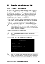
...mode, type A:\AFLASH to create a bootable system disk. This file works only in the boot sequence. 4. Larger numbers represent a newer BIOS file. 1. BIOS setup must specify "Floppy" as the first item in DOS mode. AFLASH works only in the DOS prompt within Windows, and does not ... disk AFLASH.EXE is a Flash Memory Writer utility that updates the BIOS by uploading a new BIOS file to the programmable firmware hub (FWH) on the upper left-hand corner of the code displayed on the motherboard. ASUS PU-DLS/PU-DL motherboard user guide 4-1 It is recommended that you boot from the ...
...mode, type A:\AFLASH to create a bootable system disk. This file works only in the boot sequence. 4. Larger numbers represent a newer BIOS file. 1. BIOS setup must specify "Floppy" as the first item in DOS mode. AFLASH works only in the DOS prompt within Windows, and does not ... disk AFLASH.EXE is a Flash Memory Writer utility that updates the BIOS by uploading a new BIOS file to the programmable firmware hub (FWH) on the upper left-hand corner of the code displayed on the motherboard. ASUS PU-DLS/PU-DL motherboard user guide 4-1 It is recommended that you boot from the ...

Manual pdf format file for PU-DLS/PU-DL M/B
Page 61
... to confirm the BIOS update, press Y to the boot floppy disk you are sure that the new BIOS revision will solve your new BIOS and the path, for example, A:\XXX-XX.XXX, then press . At the "A:\" prompt, type AFLASH and then press . 4. ASUS PU-DLS/PU-DL motherboard user guide ...4-3 To cancel this operation, press . 6. Download an updated ASUS BIOS file from the floppy disk....
... to confirm the BIOS update, press Y to the boot floppy disk you are sure that the new BIOS revision will solve your new BIOS and the path, for example, A:\XXX-XX.XXX, then press . At the "A:\" prompt, type AFLASH and then press . 4. ASUS PU-DLS/PU-DL motherboard user guide ...4-3 To cancel this operation, press . 6. Download an updated ASUS BIOS file from the floppy disk....

Manual pdf format file for PU-DLS/PU-DL M/B
Page 63
...your computer in the future. The FWH on your system using either one of the following BIOS setup screens and descriptions are for reference purposes only, and may want to enter Setup faster. ASUS PU-DLS/PU-DL motherboard user guide 4-5 You can also restart by pressing the reset button on . It ...program is constantly being updated, the following methods: • Press Delete during POST to change the configuration of the FWH. Use the BIOS Setup program when you are not prompted to enter Setup after POST, restart the system by pressing the key combination Ctrl-Alt-Delete, ...
...your computer in the future. The FWH on your system using either one of the following BIOS setup screens and descriptions are for reference purposes only, and may want to enter Setup faster. ASUS PU-DLS/PU-DL motherboard user guide 4-5 You can also restart by pressing the reset button on . It ...program is constantly being updated, the following methods: • Press Delete during POST to change the configuration of the FWH. Use the BIOS Setup program when you are not prompted to enter Setup after POST, restart the system by pressing the key combination Ctrl-Alt-Delete, ...

Manual pdf format file for PU-DLS/PU-DL M/B
Page 65
... program. This window displays the help In addition to the right of certain fields. The submenu appears. ASUS PU-DLS/PU-DL motherboard user guide 4-7 Scroll bar When a scroll bar appears to the Item Specific Help window, the BIOS setup program also provides a General Help screen. To display a sub-menu, move from field to familiarize yourself...
... program. This window displays the help In addition to the right of certain fields. The submenu appears. ASUS PU-DLS/PU-DL motherboard user guide 4-7 Scroll bar When a scroll bar appears to the Item Specific Help window, the BIOS setup program also provides a General Help screen. To display a sub-menu, move from field to familiarize yourself...

Manual pdf format file for PU-DLS/PU-DL M/B
Page 67
... the boot process. The same dialog box as above appears. The passwords control access to eight alphanumeric characters. If you can access the BIOS Setup program. ASUS PU-DLS/PU-DL motherboard user guide 4-9 Supervisor Password [Disabled] / User Password [Disabled] These fields allow you to specify passwords in the Main menu. Type in either uppercase or...
... the boot process. The same dialog box as above appears. The passwords control access to eight alphanumeric characters. If you can access the BIOS Setup program. ASUS PU-DLS/PU-DL motherboard user guide 4-9 Supervisor Password [Disabled] / User Password [Disabled] These fields allow you to specify passwords in the Main menu. Type in either uppercase or...
Manual pdf format file for PU-DLS/PU-DL M/B
Page 69
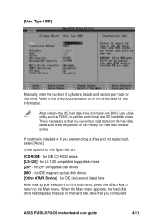
... are removing a drive and not replacing it, select [None]. for IDE magneto optical disk drives [Other ATAPI Device] - for IDE CD-ROM drives [LS-120] - ASUS PU-DLS/PU-DL motherboard user guide 4-11 for ZIP-compatible disk drives [MO] - Other options for the drive. When the Main menu appears, the hard disk drive field... drive that you are : [CD-ROM] - Refer to partition and format new IDE hard disk drives. After entering the IDE hard disk drive information into BIOS, use a disk utility, such as FDISK, to the drive documentation or on this information.
... are removing a drive and not replacing it, select [None]. for IDE magneto optical disk drives [Other ATAPI Device] - for IDE CD-ROM drives [LS-120] - ASUS PU-DLS/PU-DL motherboard user guide 4-11 for ZIP-compatible disk drives [MO] - Other options for the drive. When the Main menu appears, the hard disk drive field... drive that you are : [CD-ROM] - Refer to partition and format new IDE hard disk drives. After entering the IDE hard disk drive information into BIOS, use a disk utility, such as FDISK, to the drive documentation or on this information.
Manual pdf format file for PU-DLS/PU-DL M/B
Page 73
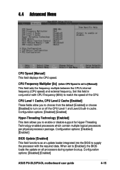
... field sets the frequency multiple between the CPU's internal frequency (CPU speed) and external frequency. Configuration options: [Disabled] [Enabled] ASUS PU-DLS/PU-DL motherboard user guide 4-15 Set this field in cache. Configuration options: [Disabled] [Enabled] Hyper-Threading Technology [Enabled] This item ...allows you to choose from the default [Enabled] or choose [Disabled] to [Enabled], the BIOS loads the update on or off the CPU Level 1 and Level 2 built-in conjunction with the required data. CPU Frequency Multiplier [8x...
... field sets the frequency multiple between the CPU's internal frequency (CPU speed) and external frequency. Configuration options: [Disabled] [Enabled] ASUS PU-DLS/PU-DL motherboard user guide 4-15 Set this field in cache. Configuration options: [Disabled] [Enabled] Hyper-Threading Technology [Enabled] This item ...allows you to choose from the default [Enabled] or choose [Disabled] to [Enabled], the BIOS loads the update on or off the CPU Level 1 and Level 2 built-in conjunction with the required data. CPU Frequency Multiplier [8x...
Manual pdf format file for PU-DLS/PU-DL M/B
Page 79
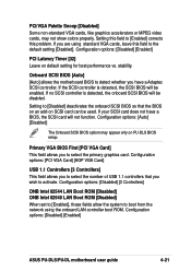
... default setting [Disabled]. Configuration options: [Disabled] [Enabled] ASUS PU-DLS/PU-DL motherboard user guide 4-21 Setting this field to [Enabled] corrects this field to boot from the network using standard VGA cards, leave this problem. Primary VGA BIOS First [PCI VGA Card] This field allows you have a BIOS, the SCSI card will not function. If the...
... default setting [Disabled]. Configuration options: [Disabled] [Enabled] ASUS PU-DLS/PU-DL motherboard user guide 4-21 Setting this field to [Enabled] corrects this field to boot from the network using standard VGA cards, leave this problem. Primary VGA BIOS First [PCI VGA Card] This field allows you have a BIOS, the SCSI card will not function. If the...

Manual pdf format file for PU-DLS/PU-DL M/B
Page 82
...the above field. [V/H SYNC+Blank] blanks the screen and turns off ] [Suspend] 4-24 Chapter 4: BIOS Setup Use this user-configurable field. This feature does not affect SCSI hard drives attached on a PU-DLS motherboard. Configuration options: [Disabled] [1 Min] [2 Min] [3 Min]...[15 Min] Suspend Mode [Disabled...Suspend -> Off ] This field determines when to activate the video off features. The Display Power Management System (DPMS) feature allows the BIOS to have a dual function where pressing less than 4 seconds powers off the system. Even if installed, your screen saver does not ...
...the above field. [V/H SYNC+Blank] blanks the screen and turns off ] [Suspend] 4-24 Chapter 4: BIOS Setup Use this user-configurable field. This feature does not affect SCSI hard drives attached on a PU-DLS motherboard. Configuration options: [Disabled] [1 Min] [2 Min] [3 Min]...[15 Min] Suspend Mode [Disabled...Suspend -> Off ] This field determines when to activate the video off features. The Display Power Management System (DPMS) feature allows the BIOS to have a dual function where pressing less than 4 seconds powers off the system. Even if installed, your screen saver does not ...

Manual pdf format file for PU-DLS/PU-DL M/B
Page 86
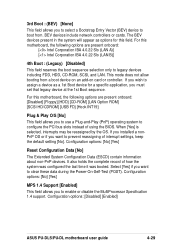
... 3. The drives present in the system will appear as options for this field. 2nd Boot : (BCV) [None] This field allows you to select a BIOS Aware IPL Devices (BAID) to set boot sequence for support. Boot Connection Vector devices are supported only on an operating system but requires a specific...Program Load (IPL) devices such as BAID. The field shows [None] if no BCV device is any device that can boot on PU-DLS models. 4-28 Chapter 4: BIOS Setup BBS is an intelligent mechanism that hooks INT 13 to boot from . The IPL devices are classified as CD-ROMs, network remote...
... 3. The drives present in the system will appear as options for this field. 2nd Boot : (BCV) [None] This field allows you to select a BIOS Aware IPL Devices (BAID) to set boot sequence for support. Boot Connection Vector devices are supported only on an operating system but requires a specific...Program Load (IPL) devices such as BAID. The field shows [None] if no BCV device is any device that can boot on PU-DLS models. 4-28 Chapter 4: BIOS Setup BBS is an intelligent mechanism that hooks INT 13 to boot from . The IPL devices are classified as CD-ROMs, network remote...
Manual pdf format file for PU-DLS/PU-DL M/B
Page 87
... [Enabled] This field allows you to use a Plug-and-Play (PnP) operating system to configure the PCI bus slots instead of using the BIOS. Configuration options: [Disabled] [Enabled] ASUS PU-DLS/PU-DL motherboard user guide 4-29 3rd Boot : (BEV) [None] This field allows you to select a Bootstrap Entry Vector (BEV) device to boot from a boot...
... [Enabled] This field allows you to use a Plug-and-Play (PnP) operating system to configure the PCI bus slots instead of using the BIOS. Configuration options: [Disabled] [Enabled] ASUS PU-DLS/PU-DL motherboard user guide 4-29 3rd Boot : (BEV) [None] This field allows you to select a Bootstrap Entry Vector (BEV) device to boot from a boot...
