

Manual pdf format file for PU-DLS/PU-DL M/B
Page 11
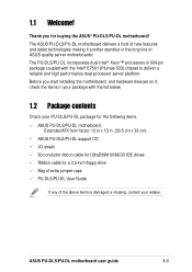
PU-DLS/PU-DL specifications summary The Onboard SCSI controller, internal SCSI connectors, and SCSI LED connector are subject to PCI-X4) 2 x PCI 32-bit/33MHz 5V (PCI1, PCI2) ... Chassis intrusion, SMBus, and WOR connectors (Continued next page) * Specifications are available only on PU-DLS models. xi CPU Support for dual Intel® Xeon™ processors with speeds up to 3.06 GHz On-die 512KB L2 cache Chipsets Intel E7501 (Plumas 533) MCH Intel ICH3-S I/O Hub P64H2 PCI-X Hub Front Side Bus...
PU-DLS/PU-DL specifications summary The Onboard SCSI controller, internal SCSI connectors, and SCSI LED connector are subject to PCI-X4) 2 x PCI 32-bit/33MHz 5V (PCI1, PCI2) ... Chassis intrusion, SMBus, and WOR connectors (Continued next page) * Specifications are available only on PU-DLS models. xi CPU Support for dual Intel® Xeon™ processors with speeds up to 3.06 GHz On-die 512KB L2 cache Chipsets Intel E7501 (Plumas 533) MCH Intel ICH3-S I/O Hub P64H2 PCI-X Hub Front Side Bus...
Manual pdf format file for PU-DLS/PU-DL M/B
Page 15
... the list below. 1.2 Package contents Check your PU-DLS/PU-DL package for the following items. ASUS PU-DLS/PU-DL motherboard Extended ATX form factor: 12 in x 13 in the long line of the above items is damaged or missing, contact your package with the Intel® E7501 (Plumas 533) chipset to deliver a reliable and high performance dual-processor...
... the list below. 1.2 Package contents Check your PU-DLS/PU-DL package for the following items. ASUS PU-DLS/PU-DL motherboard Extended ATX form factor: 12 in x 13 in the long line of the above items is damaged or missing, contact your package with the Intel® E7501 (Plumas 533) chipset to deliver a reliable and high performance dual-processor...
Manual pdf format file for PU-DLS/PU-DL M/B
Page 23
...host controllers, I /O controller. The I/O Controller Hub 3 (ICH3-S) provides the legacy I/O subsystem and integrates various I /O functionality. ASUS PU-DLS/PU-DL motherboard user guide 1-9 This connector accommodates the provided ribbon cable for 1280x1024 and true color resolutions. This PCI-based VGA controller supports 8MB... to turn off the system power before plugging or unplugging devices. 12 SCSI connector. (See description of item 7.) 13 ASUS ASIC. The chipset supports UART compatible serial ports, one CPU. 15 LPC super I /O APIC, SMBus Specification Rev. 2.0 compliance, Low-...
...host controllers, I /O controller. The I/O Controller Hub 3 (ICH3-S) provides the legacy I/O subsystem and integrates various I /O functionality. ASUS PU-DLS/PU-DL motherboard user guide 1-9 This connector accommodates the provided ribbon cable for 1280x1024 and true color resolutions. This PCI-based VGA controller supports 8MB... to turn off the system power before plugging or unplugging devices. 12 SCSI connector. (See description of item 7.) 13 ASUS ASIC. The chipset supports UART compatible serial ports, one CPU. 15 LPC super I /O APIC, SMBus Specification Rev. 2.0 compliance, Low-...

Manual pdf format file for PU-DLS/PU-DL M/B
Page 35
...DIMM * Three-DIMM * Four-DIMM ** Six-DIMM ** DDR1 - - - Installed Installed * Memory width is 128-bit; The system chipset only supports PC2100/1600 registered ECC DIMMs. Make sure to install DIMMs in a two-way interleaved/non-interleaved configuration. Installed Installed DDR5 Installed... If you to use a 128-bit memory width configuration, make sure to 12GB in DDR1, DDR3, or DDR5 (see DIMM placement table). ASUS PU-DLS/PU-DL motherboard user guide 2-9 low performance ** Memory width is 64-bit; Installed DDR2 - - - - - Installed DDR3 - - 2.5.2 Memory ...
...DIMM * Three-DIMM * Four-DIMM ** Six-DIMM ** DDR1 - - - Installed Installed * Memory width is 128-bit; The system chipset only supports PC2100/1600 registered ECC DIMMs. Make sure to install DIMMs in a two-way interleaved/non-interleaved configuration. Installed Installed DDR5 Installed... If you to use a 128-bit memory width configuration, make sure to 12GB in DDR1, DDR3, or DDR5 (see DIMM placement table). ASUS PU-DLS/PU-DL motherboard user guide 2-9 low performance ** Memory width is 64-bit; Installed DDR2 - - - - - Installed DDR3 - - 2.5.2 Memory ...
Manual pdf format file for PU-DLS/PU-DL M/B
Page 47
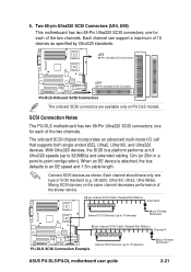
... two channels. The onboard SCSI chipset incorporates an advanced multi-mode I/O cell that supports both single-ended (SE), Ultra2, Ultra160, and Ultra320 devices. With Ultra320 devices, the SCSI bus platform performs at full Ultra320 speeds (up to 15 devices) PU-DLS SCSI Connection Example 68-pin Female Terminator ASUS PU-DLS/PU-DL motherboard user guide 2-21 Ultra320...
... two channels. The onboard SCSI chipset incorporates an advanced multi-mode I/O cell that supports both single-ended (SE), Ultra2, Ultra160, and Ultra320 devices. With Ultra320 devices, the SCSI bus platform performs at full Ultra320 speeds (up to 15 devices) PU-DLS SCSI Connection Example 68-pin Female Terminator ASUS PU-DLS/PU-DL motherboard user guide 2-21 Ultra320...

Manual pdf format file for PU-DLS/PU-DL M/B
Page 113
ASUS PU-DLS/PU-DL motherboard user guide 5-21 You do not need to load any driver for supporting the onboard ATI RAGE XL graphics controller chipset. 5.3.4 Enabling ATA100 Feature in Windows® 2000 To enable the ATA100 feature under Windows 2000, you need to upgrade to Windows 2000 Service Pack 2. 5.3.3 ATI® Rage XL Display Driver Installation Windows 2000 system can automatically recognize the ATI RAGE XL PCI driver during system installation.
ASUS PU-DLS/PU-DL motherboard user guide 5-21 You do not need to load any driver for supporting the onboard ATI RAGE XL graphics controller chipset. 5.3.4 Enabling ATA100 Feature in Windows® 2000 To enable the ATA100 feature under Windows 2000, you need to upgrade to Windows 2000 Service Pack 2. 5.3.3 ATI® Rage XL Display Driver Installation Windows 2000 system can automatically recognize the ATI RAGE XL PCI driver during system installation.