
Manual pdf format file for PU-DLS/PU-DL M/B
Page 28
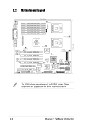
These components are available only on PU-DLS models. 30.5cm (12in) 2.2 Motherboard layout ® PU-DLS mPGA 604 Socket 1 (u50) J14 PS/2 T: Mouse B: Keyboard USB1 USB2 COM1 33cm (13in) DDR6 (64/72 bit, 184-pin module) DDR5 (64/72 bit, 184-..., 100MHz 3V) PCI2 (32-bit, 33MHz 5V) PCI1 (32-bit, 33MHz 5V) ERMC CON2 VGA RAM J2 ATI RAGE XL VGA Controller J3 CR2032 3V Lithium Cell CMOS Power Adaptec AIC-7902W SCSI Controller Super I/O ASUS ASIC with Hardware Monitor J4 J6 WOR1 Intel I/O Controller Hub (ICH3-S) FLOPPY1 SCSI-B 34 68 CPULED1...
These components are available only on PU-DLS models. 30.5cm (12in) 2.2 Motherboard layout ® PU-DLS mPGA 604 Socket 1 (u50) J14 PS/2 T: Mouse B: Keyboard USB1 USB2 COM1 33cm (13in) DDR6 (64/72 bit, 184-pin module) DDR5 (64/72 bit, 184-..., 100MHz 3V) PCI2 (32-bit, 33MHz 5V) PCI1 (32-bit, 33MHz 5V) ERMC CON2 VGA RAM J2 ATI RAGE XL VGA Controller J3 CR2032 3V Lithium Cell CMOS Power Adaptec AIC-7902W SCSI Controller Super I/O ASUS ASIC with Hardware Monitor J4 J6 WOR1 Intel I/O Controller Hub (ICH3-S) FLOPPY1 SCSI-B 34 68 CPULED1...
Manual pdf format file for PU-DLS/PU-DL M/B
Page 43
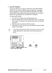
...in CMOS. Keep the cap on CLRTC jumper default position. Plug the power cord and turn ON the computer. 4. Except when clearing the RTC RAM, never remove the cap on pins 1-2 for about 5~10 seconds, then move the cap back to pins 1-2. You can clear the CMOS ...by erasing the CMOS RTC RAM data. To erase the RTC RAM: 1. Turn OFF the computer and unplug the power cord. 2. 7. Removing the cap will cause system boot failure! ® PU-DLS PU-DLS Clear RTC RAM J3 12 23 Clear CMOS Normal (Default) ASUS PU-DLS/PU-DL motherboard user guide 2-17 Clear RTC RAM (J3) This jumper ...
...in CMOS. Keep the cap on CLRTC jumper default position. Plug the power cord and turn ON the computer. 4. Except when clearing the RTC RAM, never remove the cap on pins 1-2 for about 5~10 seconds, then move the cap back to pins 1-2. You can clear the CMOS ...by erasing the CMOS RTC RAM data. To erase the RTC RAM: 1. Turn OFF the computer and unplug the power cord. 2. 7. Removing the cap will cause system boot failure! ® PU-DLS PU-DLS Clear RTC RAM J3 12 23 Clear CMOS Normal (Default) ASUS PU-DLS/PU-DL motherboard user guide 2-17 Clear RTC RAM (J3) This jumper ...

Manual pdf format file for PU-DLS/PU-DL M/B
Page 63
... what you can update using either one of the following BIOS setup screens and descriptions are installing a motherboard, reconfiguring your BIOS." ASUS PU-DLS/PU-DL motherboard user guide 4-5 4.2 BIOS Setup program This motherboard supports a programmable firmware hub (FWH) that the computer can recognize these ...changes and record them in the CMOS RAM of the FWH. If you may want to enter the Setup utility. Do this utility. For example, you don't press Delete,...
... what you can update using either one of the following BIOS setup screens and descriptions are installing a motherboard, reconfiguring your BIOS." ASUS PU-DLS/PU-DL motherboard user guide 4-5 4.2 BIOS Setup program This motherboard supports a programmable firmware hub (FWH) that the computer can recognize these ...changes and record them in the CMOS RAM of the FWH. If you may want to enter the Setup utility. Do this utility. For example, you don't press Delete,...

Manual pdf format file for PU-DLS/PU-DL M/B
Page 67
...press . To clear the password, highlight this field and press . This password allows full access to erase the R TC RAM. To confirm the password, type the password again and press . A note about passwords The BIOS Setup program allows you ...did not set to [Disabled]. The RAM data containing the password information is required to enter the BIOS Setup program and to gain full access to the ...password? See section "2.7Jumpers" for information on how to the BIOS Setup menus. ASUS PU-DLS/PU-DL motherboard user guide 4-9
...press . To clear the password, highlight this field and press . This password allows full access to erase the R TC RAM. To confirm the password, type the password again and press . A note about passwords The BIOS Setup program allows you ...did not set to [Disabled]. The RAM data containing the password information is required to enter the BIOS Setup program and to gain full access to the ...password? See section "2.7Jumpers" for information on how to the BIOS Setup menus. ASUS PU-DLS/PU-DL motherboard user guide 4-9

Manual pdf format file for PU-DLS/PU-DL M/B
Page 89
... finished making your changes before exiting. When you select this option from the Exit menu to ensure the values you are saved to the CMOS RAM. Pressing saves the changes while exiting. 4.8 Exit Menu When you made changes to fields other than system date, system time, and password, the ...RAM is sustained by an onboard backup battery and stays on even when the PC is turned off. Exit & Discard Changes Select this menu or from this option only if you do not want to save the changes that you want to exit. Select one of your changes and exit Setup. ASUS PU-DLS/PU-DL...
... finished making your changes before exiting. When you select this option from the Exit menu to ensure the values you are saved to the CMOS RAM. Pressing saves the changes while exiting. 4.8 Exit Menu When you made changes to fields other than system date, system time, and password, the ...RAM is sustained by an onboard backup battery and stays on even when the PC is turned off. Exit & Discard Changes Select this menu or from this option only if you do not want to save the changes that you want to exit. Select one of your changes and exit Setup. ASUS PU-DLS/PU-DL...

Manual pdf format file for PU-DLS/PU-DL M/B
Page 90
.... When you select this option or if you made and restore the previously saved values. Discard Changes This option allows you to the non-volatile RAM. 4-32 Chapter 4: BIOS Setup After selecting this option, a confirmation appears. Select Exit Saving Changes or make other menus and make further changes. Save Changes This... and load the previously saved values. Load Setup Defaults This option allows you select this option, a confirmation window appears. Select [Yes] to the non-volatile RAM. You can then return to other changes before saving the values to load default values.
.... When you select this option or if you made and restore the previously saved values. Discard Changes This option allows you to the non-volatile RAM. 4-32 Chapter 4: BIOS Setup After selecting this option, a confirmation appears. Select Exit Saving Changes or make other menus and make further changes. Save Changes This... and load the previously saved values. Load Setup Defaults This option allows you select this option, a confirmation window appears. Select [Yes] to the non-volatile RAM. You can then return to other changes before saving the values to load default values.