
PSCH-SR User Manual English Version
Page 9
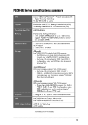
... Intel® 82547GI CSA Gigabit LAN controller Intel® 82541GI Gigabit LAN controller (32-bit) ASUS unique features ASUS Q-Fan Technology ASUS Update (continued on the next page) ix PSCH-SR Series specifications summary CPU Chipset Socket 478 for Intel® Pentium™ 4 Prescott processors with... - 2 x Serial ATA connectors (for RAID 0 and RAID 1 configurations using two SATA hard disk drives and Windows® XP) Serial ATA model IDE model storage + Adaptec® AIC-8110X support: - 4 x Serial ATA connectors (for RAID 0, RAID 1, RAID 0+1, and RAID 5 configurations using ...
... Intel® 82547GI CSA Gigabit LAN controller Intel® 82541GI Gigabit LAN controller (32-bit) ASUS unique features ASUS Q-Fan Technology ASUS Update (continued on the next page) ix PSCH-SR Series specifications summary CPU Chipset Socket 478 for Intel® Pentium™ 4 Prescott processors with... - 2 x Serial ATA connectors (for RAID 0 and RAID 1 configurations using two SATA hard disk drives and Windows® XP) Serial ATA model IDE model storage + Adaptec® AIC-8110X support: - 4 x Serial ATA connectors (for RAID 0, RAID 1, RAID 0+1, and RAID 5 configurations using ...

PSCH-SR User Manual English Version
Page 10
... WOL/WOR by PME, chassis intrusion ATX power supply (with enhanced ACPI, PnP, DMI2.0, Green PCI 2.2, PCI-X 1.0a, USB 2.0 WfM 2.0. PSCH-SR Series specifications summary Rear panel ports Internal connectors BIOS features Industry standard Manageability Power requirement Form Factor Support CD contents 1 x Serial (COM1) port 2... only) 68-pin Ultra320 SCSI connector (SCSI models only) 4 x horizontal Serial ATA connectors (SATA models only) Firmware Hub Flash ROM (4 Mb for IDE models; 8 Mb for SCSI and SATA models), Award BIOS with 4-pin 12V plug) ATX form factor: 12in x 9.8in (30.5 cm x 25...
... WOL/WOR by PME, chassis intrusion ATX power supply (with enhanced ACPI, PnP, DMI2.0, Green PCI 2.2, PCI-X 1.0a, USB 2.0 WfM 2.0. PSCH-SR Series specifications summary Rear panel ports Internal connectors BIOS features Industry standard Manageability Power requirement Form Factor Support CD contents 1 x Serial (COM1) port 2... only) 68-pin Ultra320 SCSI connector (SCSI models only) 4 x horizontal Serial ATA connectors (SATA models only) Firmware Hub Flash ROM (4 Mb for IDE models; 8 Mb for SCSI and SATA models), Award BIOS with 4-pin 12V plug) ATX form factor: 12in x 9.8in (30.5 cm x 25...

PSCH-SR User Manual English Version
Page 13
...with the list below. 1.2 Package contents Check your PSCH-SR package for buying the ASUS® PSCH-SR series motherboard! 1.1 Welcome! Before you for the following items. Item Description ASUS PSCH-SR motherboard PSCH-SR models IDE SATA SCSI ASUS PSCH-SR support CD SATA cables 2 6 2 SATA power cables... 1 3 1 SCSI cable • • 4-in-1 IDE/FDD cable set I/O shield User guide Optional items...
...with the list below. 1.2 Package contents Check your PSCH-SR package for buying the ASUS® PSCH-SR series motherboard! 1.1 Welcome! Before you for the following items. Item Description ASUS PSCH-SR motherboard PSCH-SR models IDE SATA SCSI ASUS PSCH-SR support CD SATA cables 2 6 2 SATA power cables... 1 3 1 SCSI cable • • 4-in-1 IDE/FDD cable set I/O shield User guide Optional items...
PSCH-SR User Manual English Version
Page 21
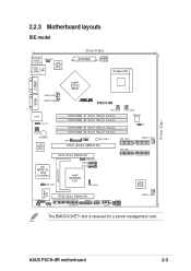
4Mbit Flash BIOS 30.5cm (12in) 2.2.3 Motherboard layouts IDE model PS/2KBMS T: Mouse B: Keyboard KBPWR1 USB2.0 T: USB1 B: USB2 Top: LAN1 Intel 82547GI Gigabit Ethernet 25cm (9.8in) ATXPWR1 PSUSMB1 Socket 478 VGA COM1 Intel® E7210 MCH REAR_FAN1 REAR_FAN2 ® PSCH-SR LAN2 LAN_LED1 LAN_EN1 LAN_EN2 BUZZER1 Intel 82541GI Gigabit Ethernet CPU_FAN1 DDR DIMM_A1 (64... I/O BMCSOCKET1 LOCATOR1 J5 PCI3 (32-bit, 33MHz 5V) PANEL1 USB34 BPSMB1 J4 FLOPPY1 COM2 FPSMB1 FRONT_FAN2 The BMCSOCKET1 slot is reserved for a server management card. ASUS PSCH-SR motherboard 2-3
4Mbit Flash BIOS 30.5cm (12in) 2.2.3 Motherboard layouts IDE model PS/2KBMS T: Mouse B: Keyboard KBPWR1 USB2.0 T: USB1 B: USB2 Top: LAN1 Intel 82547GI Gigabit Ethernet 25cm (9.8in) ATXPWR1 PSUSMB1 Socket 478 VGA COM1 Intel® E7210 MCH REAR_FAN1 REAR_FAN2 ® PSCH-SR LAN2 LAN_LED1 LAN_EN1 LAN_EN2 BUZZER1 Intel 82541GI Gigabit Ethernet CPU_FAN1 DDR DIMM_A1 (64... I/O BMCSOCKET1 LOCATOR1 J5 PCI3 (32-bit, 33MHz 5V) PANEL1 USB34 BPSMB1 J4 FLOPPY1 COM2 FPSMB1 FRONT_FAN2 The BMCSOCKET1 slot is reserved for a server management card. ASUS PSCH-SR motherboard 2-3

PSCH-SR User Manual English Version
Page 33
... drivers support "Share IRQ" or that the cards do not need IRQ assignments. shared shared shared shared - - - - - shared - - - - - - - Onboard VGA controller - ASUS PSCH-SR motherboard 2-15 BMC mini-PCI slot - shared shared shared shared - - - - - - - PCI slot 2 - shared - B CD E F G H PXIRQ0 PXIRQ1 PXIRQ2 PXIRQ3 shared shared...6 IRQ Holder for PCI Steering 12* 7 PS/2 Compatible Mouse Port 13 8 Numeric Data Processor 14* 9 Primary IDE Channel 15* 10 Secondary IDE Channel * These IRQs are usually available for this motherboard A PCIX 1 -
... drivers support "Share IRQ" or that the cards do not need IRQ assignments. shared shared shared shared - - - - - shared - - - - - - - Onboard VGA controller - ASUS PSCH-SR motherboard 2-15 BMC mini-PCI slot - shared shared shared shared - - - - - - - PCI slot 2 - shared - B CD E F G H PXIRQ0 PXIRQ1 PXIRQ2 PXIRQ3 shared shared...6 IRQ Holder for PCI Steering 12* 7 PS/2 Compatible Mouse Port 13 8 Numeric Data Processor 14* 9 Primary IDE Channel 15* 10 Secondary IDE Channel * These IRQs are usually available for this motherboard A PCIX 1 -

PSCH-SR User Manual English Version
Page 43
... connector. BIOS supports specific device bootup. one for the primary IDE connector and another for the secondary IDE connector. • Pin 20 on the IDE ribbon cable to the UltraATA100 master device. You may configure two hard disks to the secondary IDE connector. ASUS PSCH-SR motherboard 2-25 It is removed to the hard disk documentation for...
... connector. BIOS supports specific device bootup. one for the primary IDE connector and another for the secondary IDE connector. • Pin 20 on the IDE ribbon cable to the UltraATA100 master device. You may configure two hard disks to the secondary IDE connector. ASUS PSCH-SR motherboard 2-25 It is removed to the hard disk documentation for...

PSCH-SR User Manual English Version
Page 49
... This connector is for the front panel message LED that indicates the booting status. ASUS PSCH-SR motherboard 2-31 15. The read or write activities of the hard disk drive connected to the any of IDE connectors cause the hard disk drive LED to the hard disk drive LED. Pressing...RESET) This connector is for the system power LED. POWERLED+ NC POWERLEDMLED+ MLEDNC +5V GND GND SPKROUT ® PSCH-SR PANEL1 HDLED+ HDLEDNMIBTN# GND POWERBTN# GND NC RESETBTN# GND PSCH-SR System Panel Connector • System Power LED (3-pin PLED) This connector is for more than 4 seconds when the ...
... This connector is for the front panel message LED that indicates the booting status. ASUS PSCH-SR motherboard 2-31 15. The read or write activities of the hard disk drive connected to the any of IDE connectors cause the hard disk drive LED to the hard disk drive LED. Pressing...RESET) This connector is for the system power LED. POWERLED+ NC POWERLEDMLED+ MLEDNC +5V GND GND SPKROUT ® PSCH-SR PANEL1 HDLED+ HDLEDNMIBTN# GND POWERBTN# GND NC RESETBTN# GND PSCH-SR System Panel Connector • System Power LED (3-pin PLED) This connector is for more than 4 seconds when the ...

PSCH-SR User Manual English Version
Page 59
... system during the flashing process! PSCHSR-IDE DATE: 05/16/2004 Flash Type - SST 49LF004A/B /3.3V File Name to Program : 1001.bin Program Flashing Memory - 0FE00 OK 1111122222333334444455555666667777788888999990000011111222223333344444555556666677777888889999900000111112222233333444445555566666777778888899999000001111122222111112222233333444445555566666777778888899999000001111122222 11112222 Write OK 11112222 No Update 11112222 Write Fail Warning: Don't Turn Off Power Or Reset System! ASUS PSCH-SR motherboard 4-3 Type the BIOS file name...
... system during the flashing process! PSCHSR-IDE DATE: 05/16/2004 Flash Type - SST 49LF004A/B /3.3V File Name to Program : 1001.bin Program Flashing Memory - 0FE00 OK 1111122222333334444455555666667777788888999990000011111222223333344444555556666677777888889999900000111112222233333444445555566666777778888899999000001111122222111112222233333444445555566666777778888899999000001111122222 11112222 Write OK 11112222 No Update 11112222 Write Fail Warning: Don't Turn Off Power Or Reset System! ASUS PSCH-SR motherboard 4-3 Type the BIOS file name...

PSCH-SR User Manual English Version
Page 61
... to the floppy disk, then returns to File! 11112222333344445555666677778888999900001111222233334444555566667777888899990000111122223333444455556666777788889999000011112222111122223333444455556666777788889999000011112222 Message: Please Wait!Reset ASUS PSCH-SR motherboard 4-5 SST 49LF004A/B /3.3V File Name to Program : 1001.bin Now Backup System BIOS to the BIOS flashing process. All Rights Reserved For Canterwood - PSCHSR-IDE DATE: 05/16/2004 Flash Type - All Rights Reserved For Canterwood - 3. AwardBIOS...
... to the floppy disk, then returns to File! 11112222333344445555666677778888999900001111222233334444555566667777888899990000111122223333444455556666777788889999000011112222111122223333444455556666777788889999000011112222 Message: Please Wait!Reset ASUS PSCH-SR motherboard 4-5 SST 49LF004A/B /3.3V File Name to Program : 1001.bin Now Backup System BIOS to the BIOS flashing process. All Rights Reserved For Canterwood - PSCHSR-IDE DATE: 05/16/2004 Flash Type - All Rights Reserved For Canterwood - 3. AwardBIOS...

PSCH-SR User Manual English Version
Page 63
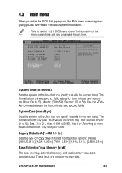
...) System Date (mm:dd:yy) Legacy Diskette A Primary IDE Master Primary IDE Slave Secondary IDE Master Secondary IDE Slave Base Memory Extended Memory Total Memory 11: 10 : 30 Wed, Mar 24 2004 [1.44M, 3.5 in.] [None] [None] [None] [None] 640K 261120K 26114K Select Menu Item Specific Help Change the day, month, year and century. ASUS PSCH-SR motherboard 4-7
...) System Date (mm:dd:yy) Legacy Diskette A Primary IDE Master Primary IDE Slave Secondary IDE Master Secondary IDE Slave Base Memory Extended Memory Total Memory 11: 10 : 30 Wed, Mar 24 2004 [1.44M, 3.5 in.] [None] [None] [None] [None] 640K 261120K 26114K Select Menu Item Specific Help Change the day, month, year and century. ASUS PSCH-SR motherboard 4-7
PSCH-SR User Manual English Version
Page 65
System Time (hh:mm:ss) System Date (mm:dd:yy) Legacy Diskette A Primary IDE Master Primary IDE Slave Secondary IDE Master Secondary IDE Slave Base Memory Extended Memory Total Memory 11: 10 : 30 Wed, Mar 24 2004 [1.44M, 3.5 in .] Base/Extended/Total Memory [xxxK] The base memory, extended .... Valid values for information on the menu screen items and how to 59). Use the key to move between the month, day, and year fields. ASUS PSCH-SR motherboard 4-9 Use the key to move between the hour, minute, and second fields. The format is hour:minute:second.
System Time (hh:mm:ss) System Date (mm:dd:yy) Legacy Diskette A Primary IDE Master Primary IDE Slave Secondary IDE Master Secondary IDE Slave Base Memory Extended Memory Total Memory 11: 10 : 30 Wed, Mar 24 2004 [1.44M, 3.5 in .] Base/Extended/Total Memory [xxxK] The base memory, extended .... Valid values for information on the menu screen items and how to 59). Use the key to move between the month, day, and year fields. ASUS PSCH-SR motherboard 4-9 Use the key to move between the hour, minute, and second fields. The format is hour:minute:second.

PSCH-SR User Manual English Version
Page 67
... S.M.A.R.T. To manually enter the number of cylinder, head, precomp, landing zone, and sector per track for supported IDE drives. Refer to [CHS]. ASUS PSCH-SR motherboard 4-11 Note: PRECOMP=65535 means NONE. Configuration options: [Disabled] [Auto] Manually detecting an IDE drive If you wish to manually enter the drive information, set to manually configure an...
... S.M.A.R.T. To manually enter the number of cylinder, head, precomp, landing zone, and sector per track for supported IDE drives. Refer to [CHS]. ASUS PSCH-SR motherboard 4-11 Note: PRECOMP=65535 means NONE. Configuration options: [Disabled] [Auto] Manually detecting an IDE drive If you wish to manually enter the drive information, set to manually configure an...

PSCH-SR User Manual English Version
Page 69
ASUS PSCH-SR motherboard 4-13 4.3.2 Primary IDE Slave When configuring a drive as Primary IDE Slave, refer to section "4.3.1 Primary IDE Master" for the menu item descriptions. 4.3.3 Secondary IDE Master When configuring a drive as Secondary IDE Master, refer to section "4.3.1 Primary IDE Master" for the menu item descriptions. 4.3.4 Secondary IDE Slave When configuring a drive as Secondary IDE Slave, refer to section "4.3.1 Primary IDE Master" for the menu item descriptions.
ASUS PSCH-SR motherboard 4-13 4.3.2 Primary IDE Slave When configuring a drive as Primary IDE Slave, refer to section "4.3.1 Primary IDE Master" for the menu item descriptions. 4.3.3 Secondary IDE Master When configuring a drive as Secondary IDE Master, refer to section "4.3.1 Primary IDE Master" for the menu item descriptions. 4.3.4 Secondary IDE Slave When configuring a drive as Secondary IDE Slave, refer to section "4.3.1 Primary IDE Master" for the menu item descriptions.

PSCH-SR User Manual English Version
Page 79
.... Refer to [Disabled] disables the onboard SATA controller. The options for details on the setting of the installed IDE devices into a disk array. Configuration options: [Primary Master] [Secondary Master] [SATA0 master] SATA1 master] ASUS PSCH-SR motherboard 4-23 Setting to the software installation guide for these items vary depending on RAID configuration. The RAID...
.... Refer to [Disabled] disables the onboard SATA controller. The options for details on the setting of the installed IDE devices into a disk array. Configuration options: [Primary Master] [Secondary Master] [SATA0 master] SATA1 master] ASUS PSCH-SR motherboard 4-23 Setting to the software installation guide for these items vary depending on RAID configuration. The RAID...


