
PSCH-SR User Manual English Version
Page 9
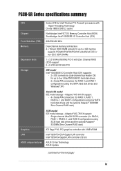
PSCH-SR Series specifications summary CPU Chipset Socket 478 for Intel® Pentium™ 4 Prescott ... DIMM sockets for up to four UltraATA100/66/33 hard disk drives - 2 x Serial ATA connectors (for RAID 0 and RAID 1 configurations using four SATA hard disk drives and the optional Adaptec® SODIMM Zero Channel RAID card) SCSI model IDE model storage + Adaptec® AIC-7901X support:...8 MB VRAM Intel® 82547GI CSA Gigabit LAN controller Intel® 82541GI Gigabit LAN controller (32-bit) ASUS unique features ASUS Q-Fan Technology ASUS Update (continued on the next page) ix
PSCH-SR Series specifications summary CPU Chipset Socket 478 for Intel® Pentium™ 4 Prescott ... DIMM sockets for up to four UltraATA100/66/33 hard disk drives - 2 x Serial ATA connectors (for RAID 0 and RAID 1 configurations using four SATA hard disk drives and the optional Adaptec® SODIMM Zero Channel RAID card) SCSI model IDE model storage + Adaptec® AIC-7901X support:...8 MB VRAM Intel® 82547GI CSA Gigabit LAN controller Intel® 82541GI Gigabit LAN controller (32-bit) ASUS unique features ASUS Q-Fan Technology ASUS Update (continued on the next page) ix
PSCH-SR User Manual English Version
Page 14
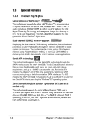
... Pentium® 4 processor. The motherboard supports up to 4 GB of system memory using the Windows® XP operating system. For IDE models, the Intel® 6300ESB ICH provides RAID 0 and RAID 1 solution for two Serial ATA interfaces using PC3200/2700/2100 ECC ... and new power design that doubles the system memory bandwidth to 6.4 GB/s data transfer rate for a multi-RAID solution using Serial ATA150 hard disk drives or Ultra320 SCSI hard disk drives. The RAID 0 (striping), RAID 1 (mirroring), RAID 0+1, and RAID 5 provide a cost-effective, reliable and high-performance server system...
... Pentium® 4 processor. The motherboard supports up to 4 GB of system memory using the Windows® XP operating system. For IDE models, the Intel® 6300ESB ICH provides RAID 0 and RAID 1 solution for two Serial ATA interfaces using PC3200/2700/2100 ECC ... and new power design that doubles the system memory bandwidth to 6.4 GB/s data transfer rate for a multi-RAID solution using Serial ATA150 hard disk drives or Ultra320 SCSI hard disk drives. The RAID 0 (striping), RAID 1 (mirroring), RAID 0+1, and RAID 5 provide a cost-effective, reliable and high-performance server system...

PSCH-SR User Manual English Version
Page 15
.... USB 2.0 technology The motherboard implements the Universal Serial Bus (USB) 2.0 specification, dramatically increasing the connection speed from SCSI hard disk drives. A chassis intrusion event is backward compatible with USB 1.1. Dual Gigabit LAN solution The Intel® 82541GI and Intel®...single-channel SCSI connector are onboard to provide high-speed data transfers to the IPMI1.5 or 2.0 versions. ASUS PSCH-SR motherboard user guide 1-3 Take the advantage of the Communication Streaming Architecture (CSA) with 8 MB memory provides a reliable solution for ...
.... USB 2.0 technology The motherboard implements the Universal Serial Bus (USB) 2.0 specification, dramatically increasing the connection speed from SCSI hard disk drives. A chassis intrusion event is backward compatible with USB 1.1. Dual Gigabit LAN solution The Intel® 82541GI and Intel®...single-channel SCSI connector are onboard to provide high-speed data transfers to the IPMI1.5 or 2.0 versions. ASUS PSCH-SR motherboard user guide 1-3 Take the advantage of the Communication Streaming Architecture (CSA) with 8 MB memory provides a reliable solution for ...
PSCH-SR User Manual English Version
Page 24
...connectors 1. Serial port 6. Power supply unit SMBus connector (5-pin PSUSMB1) 2-23 2. LAN LED connector (4-pin LAN_LED1) 2-27 9. Floppy disk drive connector (34-1 pin FLOPPY1) 2-28 11. Serial connector (10-1 pin COM2 for management use) 2-30 15. DDR DIMM 2-11 2. ...pin SASI_EN1) 2-18 5. DDR voltage regulator (3-pin J6) 2-21 9. LAN1 port 3. USB 2.0 ports 1 and 2 7. IDE connectors (40-1 pin PRI_IDE1 [blue], SEC_IDE1 [black) 2-25 6. Hard disk drive/SCSI LED switch (4-pin J4) 2-20 8. Front panel SMBus connector (6-1 pin FPSMB1 [white]) 2-23 3. ATX power connectors...
...connectors 1. Serial port 6. Power supply unit SMBus connector (5-pin PSUSMB1) 2-23 2. LAN LED connector (4-pin LAN_LED1) 2-27 9. Floppy disk drive connector (34-1 pin FLOPPY1) 2-28 11. Serial connector (10-1 pin COM2 for management use) 2-30 15. DDR DIMM 2-11 2. ...pin SASI_EN1) 2-18 5. DDR voltage regulator (3-pin J6) 2-21 9. LAN1 port 3. USB 2.0 ports 1 and 2 7. IDE connectors (40-1 pin PRI_IDE1 [blue], SEC_IDE1 [black) 2-25 6. Hard disk drive/SCSI LED switch (4-pin J4) 2-20 8. Front panel SMBus connector (6-1 pin FPSMB1 [white]) 2-23 3. ATX power connectors...

PSCH-SR User Manual English Version
Page 38
... floppy disk, then turn on the system. 7. The HD/SCSI LED is enabled when no jumper cap is placed over the pins. ® PSCH-SR PSCH-SR J4 Jumper 2-20 J4 1 HD/SCSI LED Enable Chapter 2: Hardware information Force BIOS recovery (3-pin J5) This jumper allows you to update or recover...BIOS settings when it gets corrupted or destroyed. ® PSCH-SR J5 12 23 Normal Force BIOS Recovery (Default) PSCH-SR Force BIOS Recovery Setting This jumper allows you to enable or disable the front panel hard disk drive or SCSI LED. Hard disk drive/SCSI LED switch (4-pin J4) This jumper allows you...
... floppy disk, then turn on the system. 7. The HD/SCSI LED is enabled when no jumper cap is placed over the pins. ® PSCH-SR PSCH-SR J4 Jumper 2-20 J4 1 HD/SCSI LED Enable Chapter 2: Hardware information Force BIOS recovery (3-pin J5) This jumper allows you to update or recover...BIOS settings when it gets corrupted or destroyed. ® PSCH-SR J5 12 23 Normal Force BIOS Recovery (Default) PSCH-SR Force BIOS Recovery Setting This jumper allows you to enable or disable the front panel hard disk drive or SCSI LED. Hard disk drive/SCSI LED switch (4-pin J4) This jumper allows you...

PSCH-SR User Manual English Version
Page 43
...IDE ribbon cable to the secondary IDE connector. This prevents incorrect orientation when you must configure the second drive as a slave device by setting its jumper accordingly. IDE connectors (40-1 pin PRI_IDE1 [blue], SEC_IDE1 [black) This connector supports the provided UltraATA100 IDE hard... disk ribbon cable. Connect the cable's blue connector to the primary (recommended) or secondary IDE connector, then connect the gray connector to the UltraATA100 slave device and the black connector to be both master devices with two ribbon cables - 5. ASUS PSCH-SR ...
...IDE ribbon cable to the secondary IDE connector. This prevents incorrect orientation when you must configure the second drive as a slave device by setting its jumper accordingly. IDE connectors (40-1 pin PRI_IDE1 [blue], SEC_IDE1 [black) This connector supports the provided UltraATA100 IDE hard... disk ribbon cable. Connect the cable's blue connector to the primary (recommended) or secondary IDE connector, then connect the gray connector to the UltraATA100 slave device and the black connector to be both master devices with two ribbon cables - 5. ASUS PSCH-SR ...

PSCH-SR User Manual English Version
Page 44
The current Serial ATA interface allows up to one of the IDE channels (either primary or secondary channel). • The Serial ATA RAID feature (RAID 0 and RAID 1) is only available under Windows® XP. 2-26 Chapter ...RSATA_TXN2 RSATA_TXP2 GND ® PSCH-SR SATA2 SATA1 GND RSATA_RXP1 RSATA_RXN1 GND RSATA_TXN1 RSATA_TXP1 GND PSCH-SR SATA Connectors Important notes on Serial ATA • In a legacy operating system (DOS) environment, using the Adaptec HostRAID technology embedded in the Intel® 6300ESB. If you installed Serial ATA hard disk drives and Windows® XP ...
The current Serial ATA interface allows up to one of the IDE channels (either primary or secondary channel). • The Serial ATA RAID feature (RAID 0 and RAID 1) is only available under Windows® XP. 2-26 Chapter ...RSATA_TXN2 RSATA_TXP2 GND ® PSCH-SR SATA2 SATA1 GND RSATA_RXP1 RSATA_RXN1 GND RSATA_TXN1 RSATA_TXP1 GND PSCH-SR SATA Connectors Important notes on Serial ATA • In a legacy operating system (DOS) environment, using the Adaptec HostRAID technology embedded in the Intel® 6300ESB. If you installed Serial ATA hard disk drives and Windows® XP ...

PSCH-SR User Manual English Version
Page 45
... LED connector (4-pin LAN_LED1) This connector is for the LAN activity LEDs in the system front panel. ® PSCH-SR LAN_LED1 LAN1_LINKACTLED+ LAN1_LINKACTLEDLAN2_LINKACTLEDLAN2_LINKACTLED+ PSCH-SR LANLED Connector ASUS PSCH-SR motherboard 2-27 Serial ATA RAID connectors (7-pin SATA_RAID1, SATA_RAID2, SATA_RAID3, SATA_RAID4) The Serial ATA RAID connectors are no... a RAID set , make sure that you have connected the SATA cable and installed Serial ATA hard disk drives. These Serial ATA connectors support SATA hard disks that you can configure as CD-ROMs, DVD-ROMs, etc. 8. 7.
... LED connector (4-pin LAN_LED1) This connector is for the LAN activity LEDs in the system front panel. ® PSCH-SR LAN_LED1 LAN1_LINKACTLED+ LAN1_LINKACTLEDLAN2_LINKACTLEDLAN2_LINKACTLED+ PSCH-SR LANLED Connector ASUS PSCH-SR motherboard 2-27 Serial ATA RAID connectors (7-pin SATA_RAID1, SATA_RAID2, SATA_RAID3, SATA_RAID4) The Serial ATA RAID connectors are no... a RAID set , make sure that you have connected the SATA cable and installed Serial ATA hard disk drives. These Serial ATA connectors support SATA hard disks that you can configure as CD-ROMs, DVD-ROMs, etc. 8. 7.

PSCH-SR User Manual English Version
Page 47
... single channel Ultra320 SCSI connector supports SCSI hard disk drives that you may configure as a RAID set , make sure that you have connected the SCSI cable and installed SCSI devices. 12. By default, this connector comes without a jumper. ® PSCH-SR LOCATOR LOCATORLED1+ LOCATORLED1LOCATORBTN#+ GND LOCATORLED2LOCATORLED2+ PSCH-SR LOCATOR Connector ASUS PSCH-SR motherboard 2-29 The channel can support...
... single channel Ultra320 SCSI connector supports SCSI hard disk drives that you may configure as a RAID set , make sure that you have connected the SCSI cable and installed SCSI devices. 12. By default, this connector comes without a jumper. ® PSCH-SR LOCATOR LOCATORLED1+ LOCATORLED1LOCATORBTN#+ GND LOCATORLED2LOCATORLED2+ PSCH-SR LOCATOR Connector ASUS PSCH-SR motherboard 2-29 The channel can support...

PSCH-SR User Manual English Version
Page 49
...read or write activities of the hard disk drive connected to the any of IDE connectors cause the hard disk drive LED to light up when you to hear system beeps and warnings. • Hard Disk Activity (2-pin HD_LED) This connects to the hard disk drive LED. ASUS PSCH-SR motherboard 2-31 The LED lights ... on the BIOS or OS settings. 15. POWERLED+ NC POWERLEDMLED+ MLEDNC +5V GND GND SPKROUT ® PSCH-SR PANEL1 HDLED+ HDLEDNMIBTN# GND POWERBTN# GND NC RESETBTN# GND PSCH-SR System Panel Connector • System Power LED (3-pin PLED) This connector is for the system power LED. ...
...read or write activities of the hard disk drive connected to the any of IDE connectors cause the hard disk drive LED to light up when you to hear system beeps and warnings. • Hard Disk Activity (2-pin HD_LED) This connects to the hard disk drive LED. ASUS PSCH-SR motherboard 2-31 The LED lights ... on the BIOS or OS settings. 15. POWERLED+ NC POWERLEDMLED+ MLEDNC +5V GND GND SPKROUT ® PSCH-SR PANEL1 HDLED+ HDLEDNMIBTN# GND POWERBTN# GND NC RESETBTN# GND PSCH-SR System Panel Connector • System Power LED (3-pin PLED) This connector is for the system power LED. ...
PSCH-SR User Manual English Version
Page 66
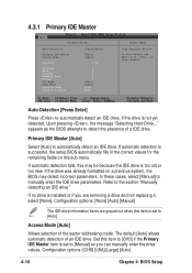
... section "Manually detecting an IDE drive." If automatic detection is too old or too new. Access Mode [Auto] Allows selection of an IDE drive. Configuration options: [CHS] [LBA] [Large] [Auto] 4-10 Chapter 4: BIOS Setup Upon pressing , the message "Detecting Hard Drive..." Configuration options: [None] [Auto] [Manual] The IDE drive information items are removing a drive and not replacing it, select...
... section "Manually detecting an IDE drive." If automatic detection is too old or too new. Access Mode [Auto] Allows selection of an IDE drive. Configuration options: [CHS] [LBA] [Large] [Auto] 4-10 Chapter 4: BIOS Setup Upon pressing , the message "Detecting Hard Drive..." Configuration options: [None] [Auto] [Manual] The IDE drive information items are removing a drive and not replacing it, select...
PSCH-SR User Manual English Version
Page 68
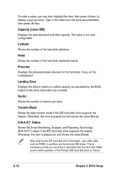
... and Reporting Technology (S.M.A.R.T.) status if the IDE hard disk drive supports the feature. Sector Shows the number of the hard disk read data from the drive documentation, then press . Transfer Mode Shows the data transfer mode if the IDE hard disk drive supports the feature. Otherwise, this item...that you entered. Cylinder Shows the number of the Primary IDE hard disk drive to "Active." 4-12 Chapter 4: BIOS Setup The value is grayed out and shows the value [None]. After entering the IDE hard disk drive information, use a disk utility, such as calculated by ...
... and Reporting Technology (S.M.A.R.T.) status if the IDE hard disk drive supports the feature. Sector Shows the number of the hard disk read data from the drive documentation, then press . Transfer Mode Shows the data transfer mode if the IDE hard disk drive supports the feature. Otherwise, this item...that you entered. Cylinder Shows the number of the Primary IDE hard disk drive to "Active." 4-12 Chapter 4: BIOS Setup The value is grayed out and shows the value [None]. After entering the IDE hard disk drive information, use a disk utility, such as calculated by ...
PSCH-SR User Manual English Version
Page 84
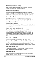
This feature does not affect SCSI hard drives. Configuration options: [Disabled] [1 Min] [2 Min] [4 Min] [8 Min] [12 Min] [20 Min] [30 Min] [40 Min] [1 Hr] Suspend Type [Stop Grant] Allows you to set the ... IRQ assignment for monitor power management. Power Management [User Define] Allows you to select the suspend type. Saving] HDD Power Down [Disabled] Shuts down any IDE hard disk drives in this for monitors without power management or "green" features. When set to activate the video off features. Saving] [Max. Configuration options: [Power Off...
This feature does not affect SCSI hard drives. Configuration options: [Disabled] [1 Min] [2 Min] [4 Min] [8 Min] [12 Min] [20 Min] [30 Min] [40 Min] [1 Hr] Suspend Type [Stop Grant] Allows you to set the ... IRQ assignment for monitor power management. Power Management [User Define] Allows you to select the suspend type. Saving] HDD Power Down [Disabled] Shuts down any IDE hard disk drives in this for monitors without power management or "green" features. When set to activate the video off features. Saving] [Max. Configuration options: [Power Off...