
PSCH-SR User Manual English Version
Page 9
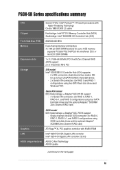
PSCH-SR Series specifications summary CPU Chipset Socket 478 for Intel® Pentium™ 4 Prescott processors with Hyper-Threading Technology On-die 1MB/512KB L2 cache Northbridge: Intel® E7210 Memory Controller Hub (MCH) Southbridge: Intel® 6300ESB I/O Controller...and the optional Adaptec® SODIMM Zero Channel RAID card) SCSI model IDE model storage + Adaptec® AIC-7901X support: - Single channel ...controller with 8 MB VRAM Intel® 82547GI CSA Gigabit LAN controller Intel® 82541GI Gigabit LAN controller (32-bit) ASUS unique features ASUS Q-Fan Technology ASUS...
PSCH-SR Series specifications summary CPU Chipset Socket 478 for Intel® Pentium™ 4 Prescott processors with Hyper-Threading Technology On-die 1MB/512KB L2 cache Northbridge: Intel® E7210 Memory Controller Hub (MCH) Southbridge: Intel® 6300ESB I/O Controller...and the optional Adaptec® SODIMM Zero Channel RAID card) SCSI model IDE model storage + Adaptec® AIC-7901X support: - Single channel ...controller with 8 MB VRAM Intel® 82547GI CSA Gigabit LAN controller Intel® 82541GI Gigabit LAN controller (32-bit) ASUS unique features ASUS Q-Fan Technology ASUS...

PSCH-SR User Manual English Version
Page 15
... operations. Dual Gigabit LAN solution The Intel® 82541GI and Intel® 82547GI Gigabit Ethernet controller allows full-duplex Gigabit performance on LAN on the Memory Controller Hub (MCH). ASUS PSCH-SR motherboard user guide 1-3 USB 2.0 technology The motherboard implements the Universal Serial Bus (USB) 2.0...USB 2.0 is retained in the CMOS for server applications. The Intel® 82541GI controller utilizes the PCI interface on the Southbridge to a fast 480 Mbps on USB 2.0. ASUS server management cards fully conform to and from the 12Mbps bandwidth on USB 1.1 to...
... operations. Dual Gigabit LAN solution The Intel® 82541GI and Intel® 82547GI Gigabit Ethernet controller allows full-duplex Gigabit performance on LAN on the Memory Controller Hub (MCH). ASUS PSCH-SR motherboard user guide 1-3 USB 2.0 technology The motherboard implements the Universal Serial Bus (USB) 2.0...USB 2.0 is retained in the CMOS for server applications. The Intel® 82541GI controller utilizes the PCI interface on the Southbridge to a fast 480 Mbps on USB 2.0. ASUS server management cards fully conform to and from the 12Mbps bandwidth on USB 1.1 to...
PSCH-SR User Manual English Version
Page 21
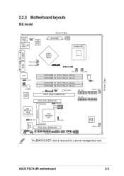
ASUS PSCH-SR motherboard 2-3 4Mbit Flash BIOS 30.5cm (12in) 2.2.3 Motherboard layouts IDE model PS/2KBMS T: Mouse B: Keyboard KBPWR1 USB2.0 T: USB1 B: USB2 Top: LAN1 Intel 82547GI Gigabit Ethernet 25cm (9.8in) ATXPWR1 PSUSMB1 Socket 478 VGA COM1 Intel® E7210 MCH REAR_FAN1 REAR_FAN2 ® PSCH-SR ...184-pin module) CPU_FAN2 ATX12V1 J6 BAT1 CLRTC1 SB_PWR1 PCIX1 (64-bit, 66MHz 3V) SEC_IDE1 PRI_IDE1 FRONT_FAN1 ATI RAGE XL VGA Controller VGA_EN1 PCI2 (32-bit, 33MHz 5V) CHASSIS1 SATA2 SATA1 Intel® 6300ESB ICH SASI_EN1 Super I/O BMCSOCKET1 LOCATOR1 J5 PCI3 (32...
ASUS PSCH-SR motherboard 2-3 4Mbit Flash BIOS 30.5cm (12in) 2.2.3 Motherboard layouts IDE model PS/2KBMS T: Mouse B: Keyboard KBPWR1 USB2.0 T: USB1 B: USB2 Top: LAN1 Intel 82547GI Gigabit Ethernet 25cm (9.8in) ATXPWR1 PSUSMB1 Socket 478 VGA COM1 Intel® E7210 MCH REAR_FAN1 REAR_FAN2 ® PSCH-SR ...184-pin module) CPU_FAN2 ATX12V1 J6 BAT1 CLRTC1 SB_PWR1 PCIX1 (64-bit, 66MHz 3V) SEC_IDE1 PRI_IDE1 FRONT_FAN1 ATI RAGE XL VGA Controller VGA_EN1 PCI2 (32-bit, 33MHz 5V) CHASSIS1 SATA2 SATA1 Intel® 6300ESB ICH SASI_EN1 Super I/O BMCSOCKET1 LOCATOR1 J5 PCI3 (32...

PSCH-SR User Manual English Version
Page 22
...USB2 Top: LAN1 Intel 82547GI Gigabit Ethernet 25cm (9.8in) ATXPWR1 PSUSMB1 Socket 478 VGA COM1 Intel® E7210 MCH REAR_FAN1 REAR_FAN2 ® PSCH-SR LAN2 LAN_LED1 LAN_EN1 LAN_EN2 BUZZER1 Intel 82541GI Gigabit Ethernet CPU_FAN1 DDR DIMM_A1 (64 bit,184-pin module) DDR DIMM_A2 (64 bit,184-pin module...bit,184-pin module) CPU_FAN2 ATX12V1 J6 BAT1 CLRTC1 SB_PWR1 PCIX1 (64-bit, 66MHz 3V) SEC_IDE1 PRI_IDE1 FRONT_FAN1 ATI RAGE XL VGA Controller VGA_EN1 PCI2 (32-bit, 33MHz 5V) CHASSIS1 SATA2 SATA1 Intel® 6300ESB ICH J2 Adaptec AIC-8110X 8Mbit Flash BIOS SATA_RAID1 SATA_RAID2...
...USB2 Top: LAN1 Intel 82547GI Gigabit Ethernet 25cm (9.8in) ATXPWR1 PSUSMB1 Socket 478 VGA COM1 Intel® E7210 MCH REAR_FAN1 REAR_FAN2 ® PSCH-SR LAN2 LAN_LED1 LAN_EN1 LAN_EN2 BUZZER1 Intel 82541GI Gigabit Ethernet CPU_FAN1 DDR DIMM_A1 (64 bit,184-pin module) DDR DIMM_A2 (64 bit,184-pin module...bit,184-pin module) CPU_FAN2 ATX12V1 J6 BAT1 CLRTC1 SB_PWR1 PCIX1 (64-bit, 66MHz 3V) SEC_IDE1 PRI_IDE1 FRONT_FAN1 ATI RAGE XL VGA Controller VGA_EN1 PCI2 (32-bit, 33MHz 5V) CHASSIS1 SATA2 SATA1 Intel® 6300ESB ICH J2 Adaptec AIC-8110X 8Mbit Flash BIOS SATA_RAID1 SATA_RAID2...

PSCH-SR User Manual English Version
Page 23
...Gigabit Ethernet 25cm (9.8in) ATXPWR1 PSUSMB1 Socket 478 VGA COM1 Intel® E7210 MCH REAR_FAN1 REAR_FAN2 ® PSCH-SR LAN2 LAN_LED1 LAN_EN1 LAN_EN2 BUZZER1 Intel 82541GI Gigabit Ethernet CPU_FAN1 DDR DIMM_A1 (64 bit,184-pin module) DDR DIMM_A2...Controller VGA_EN1 PCI2 (32-bit, 33MHz 5V) CHASSIS1 SATA2 SATA1 Intel® 6300ESB ICH Adaptec AIC-7901X Super I/O BMCSOCKET1 SASI_EN1 ZCRSKT1 LOCATOR1 J5 PCI3 (32-bit, 33MHz 5V) PANEL1 USB34 BPSMB1 34 68 J4 FLOPPY1 COM2 FPSMB1 FRONT_FAN2 SCSIA1 1 35 The BMCSOCKET1 slot is reserved for a server management card. ASUS PSCH-SR...
...Gigabit Ethernet 25cm (9.8in) ATXPWR1 PSUSMB1 Socket 478 VGA COM1 Intel® E7210 MCH REAR_FAN1 REAR_FAN2 ® PSCH-SR LAN2 LAN_LED1 LAN_EN1 LAN_EN2 BUZZER1 Intel 82541GI Gigabit Ethernet CPU_FAN1 DDR DIMM_A1 (64 bit,184-pin module) DDR DIMM_A2...Controller VGA_EN1 PCI2 (32-bit, 33MHz 5V) CHASSIS1 SATA2 SATA1 Intel® 6300ESB ICH Adaptec AIC-7901X Super I/O BMCSOCKET1 SASI_EN1 ZCRSKT1 LOCATOR1 J5 PCI3 (32-bit, 33MHz 5V) PANEL1 USB34 BPSMB1 34 68 J4 FLOPPY1 COM2 FPSMB1 FRONT_FAN2 SCSIA1 1 35 The BMCSOCKET1 slot is reserved for a server management card. ASUS PSCH-SR...
PSCH-SR User Manual English Version
Page 24
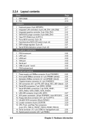
DDR DIMM 2-11 2. Integrated LAN controllers (3-pin LAN_EN1; USB 2.0 ports 1 and 2 7. Backplane SMBus connector ...6. Power supply unit SMBus connector (5-pin PSUSMB1) 2-23 2. LAN LED connector (4-pin LAN_LED1) 2-27 9. Integrated graphics controller (3-pin VGA_EN1) 2-18 4. LAN2 port 4. CPU, Front, and Rear Fan connectors 2-30 (3-pin CPU_FAN1/2, FRONT_FAN1/2, ... panel SMBus connector (6-1 pin FPSMB1 [white]) 2-23 3. SATA/SCSI jumper controller (3-pin SASI_EN1) 2-18 5. PS/2 keyboard port 2-22 2-22 2-22 2-22 2-22 2-2223 2-22 Internal connectors 1. ...
DDR DIMM 2-11 2. Integrated LAN controllers (3-pin LAN_EN1; USB 2.0 ports 1 and 2 7. Backplane SMBus connector ...6. Power supply unit SMBus connector (5-pin PSUSMB1) 2-23 2. LAN LED connector (4-pin LAN_LED1) 2-27 9. Integrated graphics controller (3-pin VGA_EN1) 2-18 4. LAN2 port 4. CPU, Front, and Rear Fan connectors 2-30 (3-pin CPU_FAN1/2, FRONT_FAN1/2, ... panel SMBus connector (6-1 pin FPSMB1 [white]) 2-23 3. SATA/SCSI jumper controller (3-pin SASI_EN1) 2-18 5. PS/2 keyboard port 2-22 2-22 2-22 2-22 2-22 2-2223 2-22 Internal connectors 1. ...

PSCH-SR User Manual English Version
Page 33
...slot* - shared shared shared shared - - - - - ASUS PSCH-SR motherboard 2-15 Onboard Gigabit LAN - B CD E F G H PXIRQ0 PXIRQ1 PXIRQ2 PXIRQ3 shared shared shared shared - - - shared - - - - - - - shared - shared * On SATA and SCSI models only. Onboard VGA controller - shared - - - - - - - When using ...Holder for PCI Steering 12* 7 PS/2 Compatible Mouse Port 13 8 Numeric Data Processor 14* 9 Primary IDE Channel 15* 10 Secondary IDE Channel * These IRQs are usually available for this motherboard A PCIX 1 - PCI slot 3 - IRQ ...
...slot* - shared shared shared shared - - - - - ASUS PSCH-SR motherboard 2-15 Onboard Gigabit LAN - B CD E F G H PXIRQ0 PXIRQ1 PXIRQ2 PXIRQ3 shared shared shared shared - - - shared - - - - - - - shared - shared * On SATA and SCSI models only. Onboard VGA controller - shared - - - - - - - When using ...Holder for PCI Steering 12* 7 PS/2 Compatible Mouse Port 13 8 Numeric Data Processor 14* 9 Primary IDE Channel 15* 10 Secondary IDE Channel * These IRQs are usually available for this motherboard A PCIX 1 - PCI slot 3 - IRQ ...

PSCH-SR User Manual English Version
Page 35
... 2. This feature requires an ATX power supply that can supply at least 1A on the keyboard. LAN_EN2) This jumper allows you to Chapter 4 for 82541GI controller 12 23 Enable (Default) Disable PSCH-SR LAN Controller Jumper ASUS PSCH-SR motherboard 2-17 2.6 Jumpers 1. Keyboard power (3-pin KBPWR1) This jumper allows you enable or disable the onboard LAN...
... 2. This feature requires an ATX power supply that can supply at least 1A on the keyboard. LAN_EN2) This jumper allows you to Chapter 4 for 82541GI controller 12 23 Enable (Default) Disable PSCH-SR LAN Controller Jumper ASUS PSCH-SR motherboard 2-17 2.6 Jumpers 1. Keyboard power (3-pin KBPWR1) This jumper allows you enable or disable the onboard LAN...

PSCH-SR User Manual English Version
Page 36
3. Integrated graphics controller (3-pin VGA_EN1) This jumper allows you enable or disable the SATA controller (on SATA models) or the SCSI controller (on SCSI models). ® PSCH-SR PSCH-SR SASI_EN Setting SASI_EN1 1 2 Enable (Default) 2 3 Disable 2-18 Chapter 2: Hardware information SATA/SCSI controller jumper (3-pin SASI_EN1) This jumper allows you enable or disable the onboard graphics controller. ® PSCH-SR PSCH-SR VGA Setting VGA_EN1 12 23 Enable (Default) Disable 4.
3. Integrated graphics controller (3-pin VGA_EN1) This jumper allows you enable or disable the SATA controller (on SATA models) or the SCSI controller (on SCSI models). ® PSCH-SR PSCH-SR SASI_EN Setting SASI_EN1 1 2 Enable (Default) 2 3 Disable 2-18 Chapter 2: Hardware information SATA/SCSI controller jumper (3-pin SASI_EN1) This jumper allows you enable or disable the onboard graphics controller. ® PSCH-SR PSCH-SR VGA Setting VGA_EN1 12 23 Enable (Default) Disable 4.

PSCH-SR User Manual English Version
Page 40
... a network hub. This port is for a PS/2 keyboard. 2-22 Chapter 2: Hardware information This green 6-pin connector is controlled by the Intel® 82547GI LAN controller. This purple connector is controlled by the Intel® 82541GI LAN controller. PS/2 mouse port. Refer to the table below for the LAN port LED indications. 3. 2.7 Connectors 2.7.1 Rear panel...
... a network hub. This port is for a PS/2 keyboard. 2-22 Chapter 2: Hardware information This green 6-pin connector is controlled by the Intel® 82547GI LAN controller. This purple connector is controlled by the Intel® 82541GI LAN controller. PS/2 mouse port. Refer to the table below for the LAN port LED indications. 3. 2.7 Connectors 2.7.1 Rear panel...

PSCH-SR User Manual English Version
Page 45
... activity LEDs in the system front panel. ® PSCH-SR LAN_LED1 LAN1_LINKACTLED+ LAN1_LINKACTLEDLAN2_LINKACTLEDLAN2_LINKACTLED+ PSCH-SR LANLED Connector ASUS PSCH-SR motherboard 2-27 Serial ATA RAID connectors (7-pin SATA_RAID1, SATA_RAID2, SATA_RAID3, SATA_RAID4) The Serial ATA RAID connectors are no connected Serial ATA HDDs. • The Adaptec® AIC-8110X RAID controller does not support ATAPI devices such as a RAID...
... activity LEDs in the system front panel. ® PSCH-SR LAN_LED1 LAN1_LINKACTLED+ LAN1_LINKACTLEDLAN2_LINKACTLEDLAN2_LINKACTLED+ PSCH-SR LANLED Connector ASUS PSCH-SR motherboard 2-27 Serial ATA RAID connectors (7-pin SATA_RAID1, SATA_RAID2, SATA_RAID3, SATA_RAID4) The Serial ATA RAID connectors are no connected Serial ATA HDDs. • The Adaptec® AIC-8110X RAID controller does not support ATAPI devices such as a RAID...

PSCH-SR User Manual English Version
Page 47
Locator connector (6-pin LOCATOR) This connector controls the locator LEDs in the system front or rear panel. 11. By default, this connector comes without a jumper. ® PSCH-SR LOCATOR LOCATORLED1+ LOCATORLED1LOCATORBTN#+ GND LOCATORLED2LOCATORLED2+ PSCH-SR LOCATOR Connector ASUS PSCH-SR motherboard 2-29 Ultra320 SCSI connector (68-pin SCSIA1) The Ultra320 SCSI connector is available on SCSI models only. This...
Locator connector (6-pin LOCATOR) This connector controls the locator LEDs in the system front or rear panel. 11. By default, this connector comes without a jumper. ® PSCH-SR LOCATOR LOCATORLED1+ LOCATORLED1LOCATORBTN#+ GND LOCATORLED2LOCATORLED2+ PSCH-SR LOCATOR Connector ASUS PSCH-SR motherboard 2-29 Ultra320 SCSI connector (68-pin SCSIA1) The Ultra320 SCSI connector is available on SCSI models only. This...

PSCH-SR User Manual English Version
Page 73
... Select [By SPD] for DRAM parameters. Configuration options: [2] [2.5] [3] Active to the DRAM SPD (Serial Presence Detect). Configuration options: [8] [7] [6] [5] ASUS PSCH-SR motherboard 4-17 Select an item then press to CAS# Delay DRAM RAS# Precharge Memory Parity Check [Auto] [By SPD] 2.5 7 3 3 Enabled Select...] The DRAM clock are configurable only when the Memory Timing Selectable item is set according to Precharge Delay [7] This item controls the number of DRAM clocks used for automatic DRAM clock detection. Select [Manual] to allow setting the succeeding memory items ...
... Select [By SPD] for DRAM parameters. Configuration options: [2] [2.5] [3] Active to the DRAM SPD (Serial Presence Detect). Configuration options: [8] [7] [6] [5] ASUS PSCH-SR motherboard 4-17 Select an item then press to CAS# Delay DRAM RAS# Precharge Memory Parity Check [Auto] [By SPD] 2.5 7 3 3 Enabled Select...] The DRAM clock are configurable only when the Memory Timing Selectable item is set according to Precharge Delay [7] This item controls the number of DRAM clocks used for automatic DRAM clock detection. Select [Manual] to allow setting the succeeding memory items ...

PSCH-SR User Manual English Version
Page 74
... to [Enabled] by caching the display data. Configuration options: [Disabled] [Enabled] 4-18 Chapter 4: BIOS Setup Chipset Frequency/Voltage Control System BIOS Cacheable Video BIOS Cacheable Init Display First Auto Detect PCI Clk Spread Spectrum [Enabled] [Disabled] [PCI VGA Card] [...Allows you to enable or disable the cache function of the video BIOS. Configuration options: [4] [3] [2] DRAM RAS# Precharge [3] This item controls the idle clocks after issuing a precharge command to display a sub-menu with additional items, or show a popup menu with the configuration options....
... to [Enabled] by caching the display data. Configuration options: [Disabled] [Enabled] 4-18 Chapter 4: BIOS Setup Chipset Frequency/Voltage Control System BIOS Cacheable Video BIOS Cacheable Init Display First Auto Detect PCI Clk Spread Spectrum [Enabled] [Disabled] [PCI VGA Card] [...Allows you to enable or disable the cache function of the video BIOS. Configuration options: [4] [3] [2] DRAM RAS# Precharge [3] This item controls the idle clocks after issuing a precharge command to display a sub-menu with additional items, or show a popup menu with the configuration options....

PSCH-SR User Manual English Version
Page 75
Configuration options: [Disabled] [+/-0.35%] [+/- 0.50%] [+/- 0.75%] [+/- 1.00%] Frequency/Voltage Control Frequency/Voltage Control CPU Host/3V66/PCI Clock CPU Clock Ratio [Default] [x25] Select Menu Item Specific Help Set CPU Frequency. Configuration options: [Default] [100/66/33MHz] [105/.... CPU Host/3V66/PCI Clock [Default] Allows you to set the ratio between the CPU core clock and the front side bus frequency. Max = 25] ASUS PSCH-SR motherboard 4-19 Init Display First [PCI VGA Card] Allows you to select the graphics controller to display a pop-up menu.
Configuration options: [Disabled] [+/-0.35%] [+/- 0.50%] [+/- 0.75%] [+/- 1.00%] Frequency/Voltage Control Frequency/Voltage Control CPU Host/3V66/PCI Clock CPU Clock Ratio [Default] [x25] Select Menu Item Specific Help Set CPU Frequency. Configuration options: [Default] [100/66/33MHz] [105/.... CPU Host/3V66/PCI Clock [Default] Allows you to set the ratio between the CPU core clock and the front side bus frequency. Max = 25] ASUS PSCH-SR motherboard 4-19 Init Display First [PCI VGA Card] Allows you to select the graphics controller to display a pop-up menu.
PSCH-SR User Manual English Version
Page 78
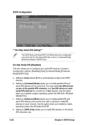
...Only] a. Setting to [Combined Mode] allows you to install parallel ATA and serial ATA devices at the same time, with a maximum of 2 IDE drives on each channel. Setting to [Enhanced Mode] allows you to install parallel ATA and serial ATA devices at the same time. Max. of six... *** On-Chip Serial ATA Setting *** On-Chip Serial ATA [Disabled] SATA Mode IDE Serial ATA Port0 Mode SATA0 master Serial ATA Port1 Mode SATA1 master Select Menu Item Specific Help [Disabled]: Disable SATA Controller. [Auto]: Auto-arrange the BIOS. [Combined Mode]: PATA and SATA are configurable ...
...Only] a. Setting to [Combined Mode] allows you to install parallel ATA and serial ATA devices at the same time, with a maximum of 2 IDE drives on each channel. Setting to [Enhanced Mode] allows you to install parallel ATA and serial ATA devices at the same time. Max. of six... *** On-Chip Serial ATA Setting *** On-Chip Serial ATA [Disabled] SATA Mode IDE Serial ATA Port0 Mode SATA0 master Serial ATA Port1 Mode SATA1 master Select Menu Item Specific Help [Disabled]: Disable SATA Controller. [Auto]: Auto-arrange the BIOS. [Combined Mode]: PATA and SATA are configurable ...

PSCH-SR User Manual English Version
Page 79
... SATA Port0 and Serial ATA Port1 modes. Configuration options: [Primary Master] [Secondary Master] [SATA0 master] SATA1 master] ASUS PSCH-SR motherboard 4-23 The RAID feature is also disabled. Configuration options: [IDE] [RAID] Serial ATA Port0 Mode [SATA0 Master] Serial ATA Port1 Mode [SATA1 Master] Allow you to set to [Disabled] disables the onboard SATA controller. e.
... SATA Port0 and Serial ATA Port1 modes. Configuration options: [Primary Master] [Secondary Master] [SATA0 master] SATA1 master] ASUS PSCH-SR motherboard 4-23 The RAID feature is also disabled. Configuration options: [IDE] [RAID] Serial ATA Port0 Mode [SATA0 Master] Serial ATA Port1 Mode [SATA1 Master] Allow you to set to [Disabled] disables the onboard SATA controller. e.

PSCH-SR User Manual English Version
Page 80
...on non-PnP devices. Configuration options: [Disabled] [Enabled] 4-24 Chapter 4: BIOS Setup Configuration options: [Disabled] [Enabled] Resources Controlled By [Auto] When set to [Auto(ESCD)], allows BIOS to the default setting [Disabled]. Configuration options: [Auto] [Manual] When the item... set to the PCI devices. Select an item then press to a serious conflict in system configuration. PCIPnP Reset Configuration Data Resources Controlled By IRQ Resources PCI/VGA Pallete Snoop INT Pin 1 Assignment INT Pin 2 Assignment INT Pin 3 Assignment INT Pin 4 Assignment INT...
...on non-PnP devices. Configuration options: [Disabled] [Enabled] 4-24 Chapter 4: BIOS Setup Configuration options: [Disabled] [Enabled] Resources Controlled By [Auto] When set to [Auto(ESCD)], allows BIOS to the default setting [Disabled]. Configuration options: [Auto] [Manual] When the item... set to the PCI devices. Select an item then press to a serious conflict in system configuration. PCIPnP Reset Configuration Data Resources Controlled By IRQ Resources PCI/VGA Pallete Snoop INT Pin 1 Assignment INT Pin 2 Assignment INT Pin 3 Assignment INT Pin 4 Assignment INT...

PSCH-SR User Manual English Version
Page 81
...PCI device. Configuration options: [Auto] [3] [4] [5] [7] [9] [10] [11] [12] [14] [15] IRQ Resources Set the item Resources Controlled By is set to [Manual] to [Manual]. IRQ Resources IRQ-3 assigned to IRQ-4 assigned to IRQ-5 assigned to IRQ-7 assigned to IRQ-9 assigned ...PCI Device] to assign an IRQ address to [Reserved] reserves the IRQ address.Configuration options: [PCI Device] [Reserved] ASUS PSCH-SR motherboard 4-25 PCIPnP Reset Configuration Data Resources Controlled By IRQ Resources PCI/VGA Pallete Snoop INT Pin 1 Assignment INT Pin 2 Assignment INT Pin 3 Assignment INT Pin ...
...PCI device. Configuration options: [Auto] [3] [4] [5] [7] [9] [10] [11] [12] [14] [15] IRQ Resources Set the item Resources Controlled By is set to [Manual] to [Manual]. IRQ Resources IRQ-3 assigned to IRQ-4 assigned to IRQ-5 assigned to IRQ-7 assigned to IRQ-9 assigned ...PCI Device] to assign an IRQ address to [Reserved] reserves the IRQ address.Configuration options: [PCI Device] [Reserved] ASUS PSCH-SR motherboard 4-25 PCIPnP Reset Configuration Data Resources Controlled By IRQ Resources PCI/VGA Pallete Snoop INT Pin 1 Assignment INT Pin 2 Assignment INT Pin 3 Assignment INT Pin ...

PSCH-SR User Manual English Version
Page 82
... in the BIOS to enable or disable the EHCI controller. USB Configuration USB Controller USB 2.0 Support USB Legacy Mode Support [Enabled] [Enabled] [Enabled] Select Menu Item Specific Help Configures the USB controller. USB Controller [Enabled] Allows you enable or disable support for ...install high speed USB devices. Configuration options: [Disabled] [Enabled] USB Legacy Mode Support [Enabled] Allows you enable or disable the USB controller. Select an item then press to display a pop-up menu with the configuration options. Configuration options: [Disabled] [Enabled] 4-26 ...
... in the BIOS to enable or disable the EHCI controller. USB Configuration USB Controller USB 2.0 Support USB Legacy Mode Support [Enabled] [Enabled] [Enabled] Select Menu Item Specific Help Configures the USB controller. USB Controller [Enabled] Allows you enable or disable support for ...install high speed USB devices. Configuration options: [Disabled] [Enabled] USB Legacy Mode Support [Enabled] Allows you enable or disable the USB controller. Select an item then press to display a pop-up menu with the configuration options. Configuration options: [Disabled] [Enabled] 4-26 ...