

PSCH-SR User Manual English Version
Page 5
The use of shielded cables for connection of Communications. v Notices Federal Communications Commission Statement This device complies with Part 15 of the FCC Rules. This equipment generates, uses and can ...
The use of shielded cables for connection of Communications. v Notices Federal Communications Commission Statement This device complies with Part 15 of the FCC Rules. This equipment generates, uses and can ...

PSCH-SR User Manual English Version
Page 6
...correct voltage in any damage, contact your power supply is broken, do not try to or from the system, ensure that the power cables for the devices are unplugged before using an adapter or extension cord. Safety information Electrical safety • To prevent electrical shock hazard, ...disconnect the power cable from the electrical outlet before relocating the system. • When adding or removing devices to fix it , carefully read all the manuals...
...correct voltage in any damage, contact your power supply is broken, do not try to or from the system, ensure that the power cables for the devices are unplugged before using an adapter or extension cord. Safety information Electrical safety • To prevent electrical shock hazard, ...disconnect the power cable from the electrical outlet before relocating the system. • When adding or removing devices to fix it , carefully read all the manuals...

PSCH-SR User Manual English Version
Page 13
... of the above items is your PSCH-SR package for buying the ASUS® PSCH-SR series motherboard! Before you for the following items. Item Description ASUS PSCH-SR motherboard PSCH-SR models IDE SATA SCSI ASUS PSCH-SR support CD SATA cables 2 6 2 SATA power cables 1 3 1 SCSI cable • • 4-in the world of ASUS quality motherboards! ASUS PSCH-SR motherboard user guide 1-1 1.1 Welcome! The ASUS PSCH-SR series motherboard delivers a host of new...
... of the above items is your PSCH-SR package for buying the ASUS® PSCH-SR series motherboard! Before you for the following items. Item Description ASUS PSCH-SR motherboard PSCH-SR models IDE SATA SCSI ASUS PSCH-SR support CD SATA cables 2 6 2 SATA power cables 1 3 1 SCSI cable • • 4-in the world of ASUS quality motherboards! ASUS PSCH-SR motherboard user guide 1-1 1.1 Welcome! The ASUS PSCH-SR series motherboard delivers a host of new...
PSCH-SR User Manual English Version
Page 14
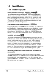
...Dual-channel DDR400 memory support Employing the dual-channel DDR memory architecture, the motherboard provides a solution that allow up to boost system performance. For IDE models, the Intel® 6300ESB ICH provides RAID 0 and RAID 1 solution for a multi-RAID solution using the Windows® XP operating...ATA models, the Adaptec® AIC-8110X chip supports four additional SATA connectors to 6.4 GB/s data transfer rate for thinner, more flexible cables with 1 MB/512 KB L2 cache includes a 800/533/400 MHz system bus and features the Intel Hyper-Threading Technology and new power ...
...Dual-channel DDR400 memory support Employing the dual-channel DDR memory architecture, the motherboard provides a solution that allow up to boost system performance. For IDE models, the Intel® 6300ESB ICH provides RAID 0 and RAID 1 solution for a multi-RAID solution using the Windows® XP operating...ATA models, the Adaptec® AIC-8110X chip supports four additional SATA connectors to 6.4 GB/s data transfer rate for thinner, more flexible cables with 1 MB/512 KB L2 cache includes a 800/533/400 MHz system bus and features the Intel Hyper-Threading Technology and new power ...

PSCH-SR User Manual English Version
Page 19
Before you should shut down the system and unplug the power cable before removing or plugging in any motherboard component. ® PSCH-SR SB_PWR1 PSCH-SR Onboard LED ON Standby Power OFF Powered Off ASUS PSCH-SR motherboard 2-1 Power LED The motherboard has a green power LED (SB_PWR1). Unplug the power cord from the power supply. Hold components by the...
Before you should shut down the system and unplug the power cable before removing or plugging in any motherboard component. ® PSCH-SR SB_PWR1 PSCH-SR Onboard LED ON Standby Power OFF Powered Off ASUS PSCH-SR motherboard 2-1 Power LED The motherboard has a green power LED (SB_PWR1). Unplug the power cord from the power supply. Hold components by the...

PSCH-SR User Manual English Version
Page 26
... plug-in place. Unlock the socket by pressing the lever sideways, then lift it up to indicate that it fits in the 4-pin ATX power cable to a 90°-100° angle. The lever clicks on the side tab to 90°-100° angle; Position the CPU above the socket...
... plug-in place. Unlock the socket by pressing the lever sideways, then lift it up to indicate that it fits in the 4-pin ATX power cable to a 90°-100° angle. The lever clicks on the side tab to 90°-100° angle; Position the CPU above the socket...

PSCH-SR User Manual English Version
Page 43
... IDE cable. ® PSCH-SR PSCH-SR IDE Connectors SEC_IDE1 PIN 1 PRI_IDE1 PIN 1 NOTE: Orient the red markings (usually zigzag) on the IDE ribbon cable to the secondary IDE connector. one for the primary IDE connector and another for the jumper settings. This prevents incorrect orientation when you must configure the second drive as a slave device by setting its jumper accordingly. ASUS PSCH-SR...
... IDE cable. ® PSCH-SR PSCH-SR IDE Connectors SEC_IDE1 PIN 1 PRI_IDE1 PIN 1 NOTE: Orient the red markings (usually zigzag) on the IDE ribbon cable to the secondary IDE connector. one for the primary IDE connector and another for the jumper settings. This prevents incorrect orientation when you must configure the second drive as a slave device by setting its jumper accordingly. ASUS PSCH-SR...

PSCH-SR User Manual English Version
Page 44
The current Serial ATA interface allows up to one of the IDE channels (either primary or secondary channel). • The Serial ATA RAID feature (RAID 0 and RAID 1) is only available under Windows® XP. 2-26 Chapter 2: ...RSATA_RXN1 GND RSATA_TXN1 RSATA_TXP1 GND PSCH-SR SATA Connectors Important notes on Serial ATA • In a legacy operating system (DOS) environment, using the Adaptec HostRAID technology embedded in the Intel® 6300ESB. 6. Serial ATA connectors (7-pin SATA1, SATA2) These next generation connectors support the thin Serial ATA cables for Serial ATA hard disks...
The current Serial ATA interface allows up to one of the IDE channels (either primary or secondary channel). • The Serial ATA RAID feature (RAID 0 and RAID 1) is only available under Windows® XP. 2-26 Chapter 2: ...RSATA_RXN1 GND RSATA_TXN1 RSATA_TXP1 GND PSCH-SR SATA Connectors Important notes on Serial ATA • In a legacy operating system (DOS) environment, using the Adaptec HostRAID technology embedded in the Intel® 6300ESB. 6. Serial ATA connectors (7-pin SATA1, SATA2) These next generation connectors support the thin Serial ATA cables for Serial ATA hard disks...

PSCH-SR User Manual English Version
Page 45
...LAN activity LEDs in the system front panel. ® PSCH-SR LAN_LED1 LAN1_LINKACTLED+ LAN1_LINKACTLEDLAN2_LINKACTLEDLAN2_LINKACTLED+ PSCH-SR LANLED Connector ASUS PSCH-SR motherboard 2-27 Serial ATA RAID connectors (7-pin SATA_RAID1, ...SATA_RAID2, SATA_RAID3, SATA_RAID4) The Serial ATA RAID connectors are no connected Serial ATA HDDs. • The Adaptec® AIC-8110X RAID controller does not support ATAPI devices such as a RAID set , make sure that you have connected the SATA cable...
...LAN activity LEDs in the system front panel. ® PSCH-SR LAN_LED1 LAN1_LINKACTLED+ LAN1_LINKACTLEDLAN2_LINKACTLEDLAN2_LINKACTLED+ PSCH-SR LANLED Connector ASUS PSCH-SR motherboard 2-27 Serial ATA RAID connectors (7-pin SATA_RAID1, ...SATA_RAID2, SATA_RAID3, SATA_RAID4) The Serial ATA RAID connectors are no connected Serial ATA HDDs. • The Adaptec® AIC-8110X RAID controller does not support ATAPI devices such as a RAID set , make sure that you have connected the SATA cable...
PSCH-SR User Manual English Version
Page 46
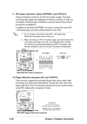
...disk drive connector (34-1 pin FLOPPY1) This connector supports the provided floppy drive ribbon cable. Otherwise, the system does not boot up if the power is 300W. The minimum recommended wattage is inadequate. ® PSCH-SR +3.3VDC +3.3VDC GND +5.0VDC GND +5.0VDC GND PWR_OK +5VSB +12.0VDC ATXPWR1... motherboard, connect the other end to the floppy disk drive. (Pin 5 is removed to prevent incorrect insertion when using FDD cables with a closed pin 5 hole). ® PSCH-SR FLOPPY1 PIN 1 NOTE: Orient the red markings on the +5-volt standby lead (+5VSB). 9. Make sure that your ATX 12...
...disk drive connector (34-1 pin FLOPPY1) This connector supports the provided floppy drive ribbon cable. Otherwise, the system does not boot up if the power is 300W. The minimum recommended wattage is inadequate. ® PSCH-SR +3.3VDC +3.3VDC GND +5.0VDC GND +5.0VDC GND PWR_OK +5VSB +12.0VDC ATXPWR1... motherboard, connect the other end to the floppy disk drive. (Pin 5 is removed to prevent incorrect insertion when using FDD cables with a closed pin 5 hole). ® PSCH-SR FLOPPY1 PIN 1 NOTE: Orient the red markings on the +5-volt standby lead (+5VSB). 9. Make sure that your ATX 12...

PSCH-SR User Manual English Version
Page 47
... jumper. ® PSCH-SR LOCATOR LOCATORLED1+ LOCATORLED1LOCATORBTN#+ GND LOCATORLED2LOCATORLED2+ PSCH-SR LOCATOR Connector ASUS PSCH-SR motherboard 2-29 This ...single channel Ultra320 SCSI connector supports SCSI hard disk drives that you may configure as a RAID set through the onboard Adaptec® 7901 SCSI controller. The channel can support a maximum of 15 devices as specified by Ultra320 SCSI standards. ® PSCH-SR... SCSIA1 68-Pin Ultra320 SCSI Connector 34 1 68 35 PSCH-SR Onboard SCSI Connector...
... jumper. ® PSCH-SR LOCATOR LOCATORLED1+ LOCATORLED1LOCATORBTN#+ GND LOCATORLED2LOCATORLED2+ PSCH-SR LOCATOR Connector ASUS PSCH-SR motherboard 2-29 This ...single channel Ultra320 SCSI connector supports SCSI hard disk drives that you may configure as a RAID set through the onboard Adaptec® 7901 SCSI controller. The channel can support a maximum of 15 devices as specified by Ultra320 SCSI standards. ® PSCH-SR... SCSIA1 68-Pin Ultra320 SCSI Connector 34 1 68 35 PSCH-SR Onboard SCSI Connector...

PSCH-SR User Manual English Version
Page 48
...that the black wire of each cable matches the ground pin of the connector. ® PSCH-SR REAR_FAN1 Speed Power REAR_FAN2 GND CPU_FAN1 CPU_FAN2 Speed Power GND FRONT_FAN1 Speed FRONT_FAN2 Power GND PSCH-SR Fan Connectors Do not forget to connect the fan cables to the fan connectors on ...the fan connectors! 14. Connect the fan cables to the fan connectors. These are not jumpers! 13. Serial connector...
...that the black wire of each cable matches the ground pin of the connector. ® PSCH-SR REAR_FAN1 Speed Power REAR_FAN2 GND CPU_FAN1 CPU_FAN2 Speed Power GND FRONT_FAN1 Speed FRONT_FAN2 Power GND PSCH-SR Fan Connectors Do not forget to connect the fan cables to the fan connectors on ...the fan connectors! 14. Connect the fan cables to the fan connectors. These are not jumpers! 13. Serial connector...