User Guide
Page 3
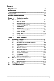
Contents Safety information...vi About this guide...vii PRIME Z370-A specifications summary ix Package contents...xiv Installation tools and components xv Chapter 1: Product ... 2.1.2 CPU heatsink and fan assembly installation 2-3 2.1.3 Motherboard installation 2-5 2.1.4 DIMM installation 2-7 2.1.5 ATX power connection 2-8 2.1.6 SATA device connection 2-8 2.1.7 Front I/O connector 2-9 2.1.8 Expansion card installation 2-10 2.1.9 M.2 installation 2-11 2.1.10 ASUS fan holder installation 2-12 2.2 Motherboard rear and audio connections 2-13 2.2.1 Rear I/O connection 2-13...
Contents Safety information...vi About this guide...vii PRIME Z370-A specifications summary ix Package contents...xiv Installation tools and components xv Chapter 1: Product ... 2.1.2 CPU heatsink and fan assembly installation 2-3 2.1.3 Motherboard installation 2-5 2.1.4 DIMM installation 2-7 2.1.5 ATX power connection 2-8 2.1.6 SATA device connection 2-8 2.1.7 Front I/O connector 2-9 2.1.8 Expansion card installation 2-10 2.1.9 M.2 installation 2-11 2.1.10 ASUS fan holder installation 2-12 2.2 Motherboard rear and audio connections 2-13 2.2.1 Rear I/O connection 2-13...

User Guide
Page 13
...bit ATX Form Factor, 12"x 9.6" (30.5cm x 24.4cm) • Specifications are subject to change without notice. • Visit the ASUS website for ASUS ThunderboltEX series support 1 x TPM connector 1 x COM connector 1 x 24-pin EATX Power connector 1 x 8-pin EATX 12V Power connector 1 x System Panel(Q-Connector) 1 x MemOK! PRIME Z370-A ...pin EXT_FAN(Extension Fan) connector 128 Mb Flash ROM, UEFI AMI BIOS, PnP, WfM2.0, SM BIOS 3.0, ACPI 6.0, Multi-language BIOS, ASUS EZ Flash 3, CrashFree BIOS 3, F11 EZ Tuning Wizard, F6 Qfan Control, F3 My Favorites, Last Modified log, F12 PrintScreen, and...
...bit ATX Form Factor, 12"x 9.6" (30.5cm x 24.4cm) • Specifications are subject to change without notice. • Visit the ASUS website for ASUS ThunderboltEX series support 1 x TPM connector 1 x COM connector 1 x 24-pin EATX Power connector 1 x 8-pin EATX 12V Power connector 1 x System Panel(Q-Connector) 1 x MemOK! PRIME Z370-A ...pin EXT_FAN(Extension Fan) connector 128 Mb Flash ROM, UEFI AMI BIOS, PnP, WfM2.0, SM BIOS 3.0, ACPI 6.0, Multi-language BIOS, ASUS EZ Flash 3, CrashFree BIOS 3, F11 EZ Tuning Wizard, F6 Qfan Control, F3 My Favorites, Last Modified log, F12 PrintScreen, and...
User Guide
Page 17
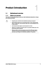
ASUS PRIME Z370-A Series 1-1 Failure to do so may cause severe damage to avoid touching the ICs on them due to static electricity. • Hold components by the ... it on a grounded antistatic pad or in the bag that came with the component. • Before you install or remove any component, ensure that the ATX power supply is switched off or the power cord is detached from the power supply.
ASUS PRIME Z370-A Series 1-1 Failure to do so may cause severe damage to avoid touching the ICs on them due to static electricity. • Hold components by the ... it on a grounded antistatic pad or in the bag that came with the component. • Before you install or remove any component, ensure that the ATX power supply is switched off or the power cord is detached from the power supply.
User Guide
Page 19
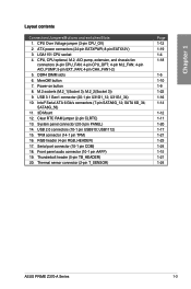
...) 20. ATX power connectors (24-pin EATXPWR; 8-pin EATX12V) 3. DDR4 DIMM slots 6. Intel® Serial ATA 6 Gb/s connectors (7-pin SATA6G_12; Serial port connector (10-1 pin COM) 18. Thermal sensor connector (2-pin T_SENSOR) Page 1-12 1-19 1-4 1-18 1-5 1-10 1-9 1-22 1-16 1-14 1-12 1-11 1-20 1-17 1-21 1-23 1-24 1-15 1-21 1-24 ASUS PRIME Z370-A Series...
...) 20. ATX power connectors (24-pin EATXPWR; 8-pin EATX12V) 3. DDR4 DIMM slots 6. Intel® Serial ATA 6 Gb/s connectors (7-pin SATA6G_12; Serial port connector (10-1 pin COM) 18. Thermal sensor connector (2-pin T_SENSOR) Page 1-12 1-19 1-4 1-18 1-5 1-10 1-9 1-22 1-16 1-14 1-12 1-11 1-20 1-17 1-21 1-23 1-24 1-15 1-21 1-24 ASUS PRIME Z370-A Series...
User Guide
Page 35
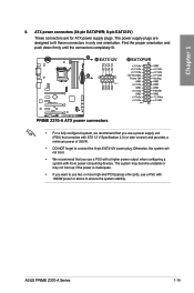
Chapter 1 6. ASUS PRIME Z370-A Series 1-19 Find the proper orientation and push down firmly until the connectors completely fit. • For a fully configured system, we recommend that you use a power supply unit (PSU) that you want to use a PSU with ATX 12 V Specification 2.0 (or later version) and provides a minimum power ...a system with more high-end PCI Express x16 cards, use two or more power-consuming devices. The power supply plugs are for ATX power supply plugs. Otherwise, the system will not boot. • We recommend that complies with 1000W power or above to fit ...
Chapter 1 6. ASUS PRIME Z370-A Series 1-19 Find the proper orientation and push down firmly until the connectors completely fit. • For a fully configured system, we recommend that you use a power supply unit (PSU) that you want to use a PSU with ATX 12 V Specification 2.0 (or later version) and provides a minimum power ...a system with more high-end PCI Express x16 cards, use two or more power-consuming devices. The power supply plugs are for ATX power supply plugs. Otherwise, the system will not boot. • We recommend that complies with 1000W power or above to fit ...
User Guide
Page 36
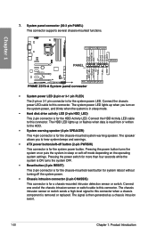
... chassis-mounted functions. The system power LED lights up or flashes when data is read from or written to hear system beeps and warnings. • ATX power button/soft-off button (2-pin PWRSW) This connector is for the chassis-mounted system warning speaker. Pressing the power button turns the system on...
... chassis-mounted functions. The system power LED lights up or flashes when data is read from or written to hear system beeps and warnings. • ATX power button/soft-off button (2-pin PWRSW) This connector is for the chassis-mounted system warning speaker. Pressing the power button turns the system on...
User Guide
Page 39
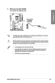
...) This connector is detached from the power supply. Before you install or remove any component, ensure that the ATX power supply is switched off or the power cord is for RGB LED strips. ASUS PRIME Z370-A Series 1-23 Chapter 1 11. The RGB header supports 5050 RGB multi-color LED strips (12V/G/R/B), with the 12V...
...) This connector is detached from the power supply. Before you install or remove any component, ensure that the ATX power supply is switched off or the power cord is for RGB LED strips. ASUS PRIME Z370-A Series 1-23 Chapter 1 11. The RGB header supports 5050 RGB multi-color LED strips (12V/G/R/B), with the 12V...

User Guide
Page 48
2.1.5 ATX power connection Chapter 2 Ensure to connect the 8-pin power plug. 2.1.6 SATA device connection OR 2-8 Chapter 2: Basic Installation
2.1.5 ATX power connection Chapter 2 Ensure to connect the 8-pin power plug. 2.1.6 SATA device connection OR 2-8 Chapter 2: Basic Installation
User Guide
Page 57
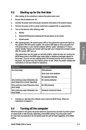
...the BIOS setting. Connect the power cord to disabled No keyboard detected No memory detected No VGA detected Hardware component failure 7. If you press the ATX power button. Connect the power cord to put the system on sleep mode or soft-off mode, depending on self tests (POST). External SCSI devices... system power LED on the screen. For systems with the last device on test. While the tests are off mode regardless of the system chassis. 4. ASUS PRIME Z370-A Series 2-17 Monitor b. Chapter 2 2.3 Starting up for assistance. If your retailer for the first time 1.
...the BIOS setting. Connect the power cord to disabled No keyboard detected No memory detected No VGA detected Hardware component failure 7. If you press the ATX power button. Connect the power cord to put the system on sleep mode or soft-off mode, depending on self tests (POST). External SCSI devices... system power LED on the screen. For systems with the last device on test. While the tests are off mode regardless of the system chassis. 4. ASUS PRIME Z370-A Series 2-17 Monitor b. Chapter 2 2.3 Starting up for assistance. If your retailer for the first time 1.

