
Motherboard Pin Definition.English
Page 2
Contents Motherboard Pin Definition 1-1 1 Headers...1-3 2 Jumpers...1-4 3 Internal Connectors 1-6 4 Onboard LEDs 1-16 5 Onboard buttons and switches 1-17 1-2 Motherboard Pin Definition
Contents Motherboard Pin Definition 1-1 1 Headers...1-3 2 Jumpers...1-4 3 Internal Connectors 1-6 4 Onboard LEDs 1-16 5 Onboard buttons and switches 1-17 1-2 Motherboard Pin Definition
Motherboard Pin Definition.English
Page 10
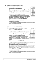
...; System warning speaker (4-pin SPEAKER) This 4-pin connector is for the chassis-mounted system warning speaker. Connect the HDD Activity LED cable to this connector. The system power LED lights up when you to hear system beeps and warnings. • ATX power button/soft-off button (2-pin PWRSW) This ...when you turn on the system power, and blinks when the system is in sleep mode. Connect the chassis power LED cable to this connector. The HDD LED lights up or flashes when data is for the chassis-mounted reset button for the system power button. Pressing the power...
...; System warning speaker (4-pin SPEAKER) This 4-pin connector is for the chassis-mounted system warning speaker. Connect the HDD Activity LED cable to this connector. The system power LED lights up when you to hear system beeps and warnings. • ATX power button/soft-off button (2-pin PWRSW) This ...when you turn on the system power, and blinks when the system is in sleep mode. Connect the chassis power LED cable to this connector. The HDD LED lights up or flashes when data is for the chassis-mounted reset button for the system power button. Pressing the power...
Motherboard Pin Definition.English
Page 11
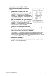
...button turns the system on or puts the system in sleep mode. Ground RESET NC PLED+ PLED- • Hard disk drive activity LED (2-pin +HDD_LED-) This 2-pin connector is for system reboot without turning off mode depending on the system power, and blinks when the...PWR_LED* Requires an ATX power supply • System warning speaker (4-pin SPEAKER) This 4-pin connector is for the system power LED. Connect the chassis power LED cable to this connector. Motherboard Pin Definition 1-11 PWR_SW SPEAKER PLED+ PLEDPWR Ground +5V_SPKO Ground Ground Speaker This 2-pin connector is...
...button turns the system on or puts the system in sleep mode. Ground RESET NC PLED+ PLED- • Hard disk drive activity LED (2-pin +HDD_LED-) This 2-pin connector is for system reboot without turning off mode depending on the system power, and blinks when the...PWR_LED* Requires an ATX power supply • System warning speaker (4-pin SPEAKER) This 4-pin connector is for the system power LED. Connect the chassis power LED cable to this connector. Motherboard Pin Definition 1-11 PWR_SW SPEAKER PLED+ PLEDPWR Ground +5V_SPKO Ground Ground Speaker This 2-pin connector is...
Motherboard Pin Definition.English
Page 12
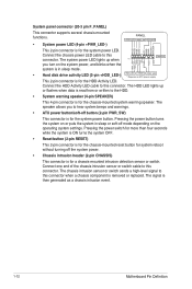
RESET +PWR_LED* Requires an ATX power supply This 2-pin connector is in sleep mode. • Hard disk drive activity LED (2-pin +HDD_LED-) +HDD_LED- Connect the chassis power LED cable to this connector. Pressing the power button turns the system on or puts the system in sleep or soft-off mode depending... button. Connect one end of the chassis intrusion sensor or switch cable to this connector. GND Reset NC PLED+ PLED- The system power LED lights up or flashes when data is read from or written to this connector when a chassis component is for the HDD Activity...
RESET +PWR_LED* Requires an ATX power supply This 2-pin connector is in sleep mode. • Hard disk drive activity LED (2-pin +HDD_LED-) +HDD_LED- Connect the chassis power LED cable to this connector. Pressing the power button turns the system on or puts the system in sleep or soft-off mode depending... button. Connect one end of the chassis intrusion sensor or switch cable to this connector. GND Reset NC PLED+ PLED- The system power LED lights up or flashes when data is read from or written to this connector when a chassis component is for the HDD Activity...

Motherboard Pin Definition.English
Page 16
... provides you press the BIOS Flashback button for BIOS update. 6. The illustration below shows the location of the onboard LED. SB_PWR ON OFF Standby Power Powered Off 2. This user-friendly design provides an intuitive way to indicate that displays the system status. 1-16 Motherboard... not light up when the KeyBot button is no hard disk drive connected to indicate the hard disk activity. KeyBot LED (KEYBOT_LED) This LED lights up when there is pressed. 5. Standby Power LED The motherboard comes with a 2-digit error code that the system is ON, in sleep mode, or in sequence ...
... provides you press the BIOS Flashback button for BIOS update. 6. The illustration below shows the location of the onboard LED. SB_PWR ON OFF Standby Power Powered Off 2. This user-friendly design provides an intuitive way to indicate that displays the system status. 1-16 Motherboard... not light up when the KeyBot button is no hard disk drive connected to indicate the hard disk activity. KeyBot LED (KEYBOT_LED) This LED lights up when there is pressed. 5. Standby Power LED The motherboard comes with a 2-digit error code that the system is ON, in sleep mode, or in sequence ...

Motherboard Pin Definition.English
Page 18
KeyBot button (KeyBot) Press this button to activate the Sonic SoundStage feature. The debug code on the Q-Code LED shows the current Sonic SoundStage profile when you press the Sonic SoundStage button. When enabled, the Slow Mode switch prevents the system from crashing, slows ...
KeyBot button (KeyBot) Press this button to activate the Sonic SoundStage feature. The debug code on the Q-Code LED shows the current Sonic SoundStage profile when you press the Sonic SoundStage button. When enabled, the Slow Mode switch prevents the system from crashing, slows ...
PRIME Z270-K Users manual English
Page 7
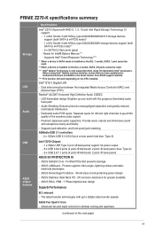
... with up your motherboard drivers and BIOS to guard the quality of the sensitive audio signals - PRIME Z270-K specifications summary Storage LAN Audio USB ASUS unique features Specifications Intel® Z270 Chipset with RAID 0, 1, 5, 10 and Intel Rapid Storage Technology 15 support - 1 x ...and quietness (continued on the CPU installed. LED-illuminated design: Brighten up to 32Gb/s data transfer speeds ASUS Fan Xpert 4 Core - ASUS Overvoltage Protection - The latest transfer technologies with the gorgeous illuminated audio trace path - ASUS DIGI+ VRM - 7 Phase digital power ...
... with up your motherboard drivers and BIOS to guard the quality of the sensitive audio signals - PRIME Z270-K specifications summary Storage LAN Audio USB ASUS unique features Specifications Intel® Z270 Chipset with RAID 0, 1, 5, 10 and Intel Rapid Storage Technology 15 support - 1 x ...and quietness (continued on the CPU installed. LED-illuminated design: Brighten up to 32Gb/s data transfer speeds ASUS Fan Xpert 4 Core - ASUS Overvoltage Protection - The latest transfer technologies with the gorgeous illuminated audio trace path - ASUS DIGI+ VRM - 7 Phase digital power ...

PRIME Z270-K Users manual English
Page 12
...; If you intend to the Recommended Power Supply Wattage Calculator at http://support.asus.com/PowerSupplyCalculator/PSCalculator. CPU, chassis, and AIO pump fan fan connectors (4-pin...details. 1-2 Chapter 1: Product introduction 1.2.1 Layout contents Connectors/Jumpers/Slots/LED 1. EATX12V GND GND GND GND PIN 1 +12V DC +12V DC...W. Clear RTC RAM (2-pin CLRTC) 10. Front panel audio connector (10-1 pin AAFP) 14. PCI slots 15. Intel® Z270 Serial ATA 6.0 Gb/s connector (7-pin SATA6G_1~6) 8. USB 3.0 connectors (20-1 pin USB3_12, USB3_34) 6. PCI Express 3.0/2.0 x16 slots...
...; If you intend to the Recommended Power Supply Wattage Calculator at http://support.asus.com/PowerSupplyCalculator/PSCalculator. CPU, chassis, and AIO pump fan fan connectors (4-pin...details. 1-2 Chapter 1: Product introduction 1.2.1 Layout contents Connectors/Jumpers/Slots/LED 1. EATX12V GND GND GND GND PIN 1 +12V DC +12V DC...W. Clear RTC RAM (2-pin CLRTC) 10. Front panel audio connector (10-1 pin AAFP) 14. PCI slots 15. Intel® Z270 Serial ATA 6.0 Gb/s connector (7-pin SATA6G_1~6) 8. USB 3.0 connectors (20-1 pin USB3_12, USB3_34) 6. PCI Express 3.0/2.0 x16 slots...

PRIME Z270-K Users manual English
Page 14
... F_PANEL) This connector supports several chassis-mounted functions. PIN 1 +HDD_LED- The system power LED lights up the Windows® UEFI operating system under RAID mode. • Intel®...2_1 socket, SATA_1 port cannot be used. • When a device is read from ASUS support website. • The M.2 slots support data transfer speed up to set up when... SATA_5/6 ports cannot be used. M.2 socket 3 These sockets allow you to this connector. Intel® Z270 Serial ATA 6.0Gb/s connectors (7-pin SATA6G_1~6) These connectors connect to this connector. GND RSTCON# NC PLED+...
... F_PANEL) This connector supports several chassis-mounted functions. PIN 1 +HDD_LED- The system power LED lights up the Windows® UEFI operating system under RAID mode. • Intel®...2_1 socket, SATA_1 port cannot be used. • When a device is read from ASUS support website. • The M.2 slots support data transfer speed up to set up when... SATA_5/6 ports cannot be used. M.2 socket 3 These sockets allow you to this connector. Intel® Z270 Serial ATA 6.0Gb/s connectors (7-pin SATA6G_1~6) These connectors connect to this connector. GND RSTCON# NC PLED+...

PRIME Z270-K Users manual English
Page 18
... USB 3.0 devices can only be used for faster and better performance from S5 mode Speed LED Status Description OFF 10Mbps connection ORANGE 100Mbps connection GREEN 1Gbps connection Activity Link Speed LED LED LAN port 4. Line In port (light blue). This port connects to the tape, CD...to a Local Area Network (LAN) through a network hub. Line Out port (lime). USB 3.0 ports (blue, Type A). LAN port LED indications Activity/Link LED Status Description Off No link Orange Linked Orange (Blinking) Data activity Orange (Blinking then steady) Ready to wake up from your USB 3.0 ...
... USB 3.0 devices can only be used for faster and better performance from S5 mode Speed LED Status Description OFF 10Mbps connection ORANGE 100Mbps connection GREEN 1Gbps connection Activity Link Speed LED LED LAN port 4. Line In port (light blue). This port connects to the tape, CD...to a Local Area Network (LAN) through a network hub. Line Out port (lime). USB 3.0 ports (blue, Type A). LAN port LED indications Activity/Link LED Status Description Off No link Orange Linked Orange (Blinking) Data activity Orange (Blinking then steady) Ready to wake up from your USB 3.0 ...

PRIME Z270-K Users manual English
Page 55
SPDIF Out Type [SPDIF] [SPDIF] Sets to an SPDIF audio output. [HDMI] Sets to an HDMI audio output. ASUS PRIME Z270-K 2-31 Configuration options: [Enabled] [Disabled] LED Lighting [Breathing Mode] Allows you to enable/disable SATA Hot Plug Support. Configuration options: [On] [Off] Hot Plug [...Disabled] (SATA6G_1 (Gray) ~ SATA6G_6(Gray)) These items allow you to set the behavior of the LED. Configuration options: [Disabled] [Enabled] 2.6.6 PCH-FW Configuration Intel Platform Trust Technology [Disabled] This item allows you set the front panel audio ...
SPDIF Out Type [SPDIF] [SPDIF] Sets to an SPDIF audio output. [HDMI] Sets to an HDMI audio output. ASUS PRIME Z270-K 2-31 Configuration options: [Enabled] [Disabled] LED Lighting [Breathing Mode] Allows you to enable/disable SATA Hot Plug Support. Configuration options: [On] [Off] Hot Plug [...Disabled] (SATA6G_1 (Gray) ~ SATA6G_6(Gray)) These items allow you to set the behavior of the LED. Configuration options: [Disabled] [Enabled] 2.6.6 PCH-FW Configuration Intel Platform Trust Technology [Disabled] This item allows you set the front panel audio ...


