Motherboard Pin Definition.English
Page 3
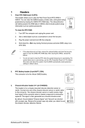
... system failure due to this connector. Connect one end of date, time, and system setup parameters by erasing the CMOS RTC RAM data. The chassis intrusion sensor or switch sends a highlevel signal to overclocking, use the chassis intrusion detection feature. Motherboard Pin Definition 1-3 ... is for a chassis-mounted intrusion detection sensor or switch. Remove the jumper caps only when you to clear the Real Time Clock (RTC) RAM in CMOS, which include system setup information such as a screwdriver to use the CPU Parameter Recall (C.P.R.) feature. Turn OFF the computer and unplug...
... system failure due to this connector. Connect one end of date, time, and system setup parameters by erasing the CMOS RTC RAM data. The chassis intrusion sensor or switch sends a highlevel signal to overclocking, use the chassis intrusion detection feature. Motherboard Pin Definition 1-3 ... is for a chassis-mounted intrusion detection sensor or switch. Remove the jumper caps only when you to clear the Real Time Clock (RTC) RAM in CMOS, which include system setup information such as a screwdriver to use the CPU Parameter Recall (C.P.R.) feature. Turn OFF the computer and unplug...
Motherboard Pin Definition.English
Page 4
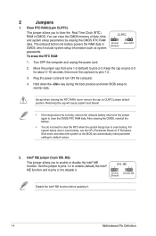
... failure! • If the steps above do not need to clear the RTC when the system hangs due to default values. 2. To erase the RTC RAM: CLRTC 12 23 Normal (Default) Clear RTC 1. Set this jumper to pins 1-2 to enable (default) the Intel® ME function and to pins 2-3 ...to enable or disable the Intel® ME function. Clear RTC RAM (3-pin CLRTC) This jumper allows you to disable it . 1-4 Motherboard Pin Definition Turn OFF the computer and unplug the power cord. 2. Except when clearing ...
... failure! • If the steps above do not need to clear the RTC when the system hangs due to default values. 2. To erase the RTC RAM: CLRTC 12 23 Normal (Default) Clear RTC 1. Set this jumper to pins 1-2 to enable (default) the Intel® ME function and to pins 2-3 ...to enable or disable the Intel® ME function. Clear RTC RAM (3-pin CLRTC) This jumper allows you to disable it . 1-4 Motherboard Pin Definition Turn OFF the computer and unplug the power cord. 2. Except when clearing ...

PRIME Z270-K Users manual English
Page 12
...contents Connectors/Jumpers/Slots/LED 1. USB 3.0 connectors (20-1 pin USB3_12, USB3_34) 6. System panel connector (20-5 pin PANEL) 9. Clear RTC RAM (2-pin CLRTC) 10. aspx?SLanguage=en-us for your system, refer to install additional devices. ATX power connectors (24-pin EATXPWR, 8-pin EATX12V...8226; If you intend to the Recommended Power Supply Wattage Calculator at http://support.asus.com/PowerSupplyCalculator/PSCalculator. Serial port connectors (10-1 pin COM) 12. PCI slots 15. Intel® Z270 Serial ATA 6.0 Gb/s connector (7-pin SATA6G_1~6) 8. Digital audio connector (4-1 pin ...
...contents Connectors/Jumpers/Slots/LED 1. USB 3.0 connectors (20-1 pin USB3_12, USB3_34) 6. System panel connector (20-5 pin PANEL) 9. Clear RTC RAM (2-pin CLRTC) 10. aspx?SLanguage=en-us for your system, refer to install additional devices. ATX power connectors (24-pin EATXPWR, 8-pin EATX12V...8226; If you intend to the Recommended Power Supply Wattage Calculator at http://support.asus.com/PowerSupplyCalculator/PSCalculator. Serial port connectors (10-1 pin COM) 12. PCI slots 15. Intel® Z270 Serial ATA 6.0 Gb/s connector (7-pin SATA6G_1~6) 8. Digital audio connector (4-1 pin ...

PRIME Z270-K Users manual English
Page 15
...module cable to this connector, then install the module to a slot opening at the back of the system chassis. +5V SPDIFOUT GND SPDIF_OUT ASUS PRIME Z270-K 1-5 These USB connectors comply with USB 2.0 specifications and supports up to re-enter data. Plug the power cord and turn ON the ...for an additional Sony/Philips Digital Interface (S/PDIF) port. Use a metal object such as date, time, and system passwords. To erase the RTC RAM: 1. USB+5V USB_P11USB_P11+ GND NC USB+5V USB_P13USB_P13+ GND NC USB 2.0 connectors (10-1 pin USB1112, USB1314) Connect a USB module cable to...
...module cable to this connector, then install the module to a slot opening at the back of the system chassis. +5V SPDIFOUT GND SPDIF_OUT ASUS PRIME Z270-K 1-5 These USB connectors comply with USB 2.0 specifications and supports up to re-enter data. Plug the power cord and turn ON the ...for an additional Sony/Philips Digital Interface (S/PDIF) port. Use a metal object such as date, time, and system passwords. To erase the RTC RAM: 1. USB+5V USB_P11USB_P11+ GND NC USB+5V USB_P13USB_P13+ GND NC USB 2.0 connectors (10-1 pin USB1112, USB1314) Connect a USB module cable to...

PRIME Z270-K Users manual English
Page 30
... and reset the motherboard to the default value. Press the power button to turn the system off then back on how to erase the RTC RAM. The BIOS screens include navigation keys and brief online help to change between the two modes. 2-6 Chapter 2: Getting started Press the reset button ... system chassis. If you failed to enter BIOS Setup using the BIOS Setup program. Entering BIOS Setup at startup To enter BIOS Setup at www.asus.com to download the latest BIOS file for details. • If the system fails to boot after POST: Press ++ simultaneously. Select the Load ...
... and reset the motherboard to the default value. Press the power button to turn the system off then back on how to erase the RTC RAM. The BIOS screens include navigation keys and brief online help to change between the two modes. 2-6 Chapter 2: Getting started Press the reset button ... system chassis. If you failed to enter BIOS Setup using the BIOS Setup program. Entering BIOS Setup at startup To enter BIOS Setup at www.asus.com to download the latest BIOS file for details. • If the system fails to boot after POST: Press ++ simultaneously. Select the Load ...

PRIME Z270-K Users manual English
Page 40
... default Not Installed. 2.4 Main menu The Main menu screen appears when you have forgotten your BIOS password, erase the CMOS Real Time Clock (RTC) RAM to clear the BIOS password. The Main menu provides you an overview of the basic system information, and allows you to erase the RTC... RAM. • The Administrator or User Password items on how to choose the BIOS language version from the options. See section 1.2 Motherboard overview for information ...
... default Not Installed. 2.4 Main menu The Main menu screen appears when you have forgotten your BIOS password, erase the CMOS Real Time Clock (RTC) RAM to clear the BIOS password. The Main menu provides you an overview of the basic system information, and allows you to erase the RTC... RAM. • The Administrator or User Password items on how to choose the BIOS language version from the options. See section 1.2 Motherboard overview for information ...


