
PR-DLSR User Manual
Page 8
... of the switches, jumpers, and connectors on the motherboard. • Chapter 3: Powering up This chapter describes the power up sequence and gives information on the ASUS PR-DLSR motherboard. How this guide This user guide contains detailed information on the BIOS beep codes. • Chapter 4: BIOS setup This chapter tells how to perform...
... of the switches, jumpers, and connectors on the motherboard. • Chapter 3: Powering up This chapter describes the power up sequence and gives information on the ASUS PR-DLSR motherboard. How this guide This user guide contains detailed information on the BIOS beep codes. • Chapter 4: BIOS setup This chapter tells how to perform...
PR-DLSR User Manual
Page 13
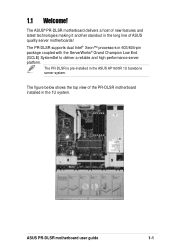
ASUS PR-DLSR motherboard user guide 1-1 The ASUS® PR-DLSR motherboard delivers a host of ASUS quality server motherboards! The figure below shows the top view of the PR-DLSR motherboard installed in the long line of new features and latest technologies making it another standout in the 1U system. 1.1 Welcome! The PR-DLSR is pre-installed in 603/604-pin package...
ASUS PR-DLSR motherboard user guide 1-1 The ASUS® PR-DLSR motherboard delivers a host of ASUS quality server motherboards! The figure below shows the top view of the PR-DLSR motherboard installed in the long line of new features and latest technologies making it another standout in the 1U system. 1.1 Welcome! The PR-DLSR is pre-installed in 603/604-pin package...

PR-DLSR User Manual
Page 15
Onboard VGA The ATI Rage-XL PCI-based VGA controller integrates an 8MB display SDRAM to support an IDE board with dual-channel bus master IDE connectors. ASUS PR-DLSR motherboard user guide 1-3 Integrated IDE bridge The motherboard includes two connectors to provide onboard video solution. The IDE connectors support Ultra DMA 66/33, PIO modes 3 & 4 devices.
Onboard VGA The ATI Rage-XL PCI-based VGA controller integrates an 8MB display SDRAM to support an IDE board with dual-channel bus master IDE connectors. ASUS PR-DLSR motherboard user guide 1-3 Integrated IDE bridge The motherboard includes two connectors to provide onboard video solution. The IDE connectors support Ultra DMA 66/33, PIO modes 3 & 4 devices.
PR-DLSR User Manual
Page 17
... the motherboard meet the stringent requirements for more control and protection to -use interface that provides more protection. ASUS PR-DLSR motherboard user guide 1-5 Chassis intrusion detection The motherboard supports chassis intrusion monitoring through the ASUS ASIC. Color-coded connectors and descriptive icons make identification easy as required by the PC '99 specification. The...
... the motherboard meet the stringent requirements for more control and protection to -use interface that provides more protection. ASUS PR-DLSR motherboard user guide 1-5 Chassis intrusion detection The motherboard supports chassis intrusion monitoring through the ASUS ASIC. Color-coded connectors and descriptive icons make identification easy as required by the PC '99 specification. The...
PR-DLSR User Manual
Page 19
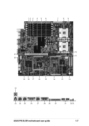
12 3 4 5 6 7 89 10 21 11 20 19 18 17 16 15 14 13 12 22 23 24 25 26 27 28 29 30 31 32 33 ASUS PR-DLSR motherboard user guide 1-7
12 3 4 5 6 7 89 10 21 11 20 19 18 17 16 15 14 13 12 22 23 24 25 26 27 28 29 30 31 32 33 ASUS PR-DLSR motherboard user guide 1-7
PR-DLSR User Manual
Page 21
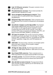
...data transfers of 160Mbps. This dual-channel 68-pin Ultra-160 SCSI connector supports up to 8MB display SDRAM for the optional ASUS Server Management daughterboards. 12 Backplane bridge board connectors. This connector provides the additional power required by PCI cards. 11 Server ... interface, ACPI power management and detection, XIO-APIC, and legacy functions 8237DMA, 8259APIC, and 8254 timer. 14 LPC super I /O functionality. ASUS PR-DLSR motherboard user guide 1-9 This power connector is for an SSI-type power supply. 10 PCI extended power connector. This Low Pin Count (LPC) ...
...data transfers of 160Mbps. This dual-channel 68-pin Ultra-160 SCSI connector supports up to 8MB display SDRAM for the optional ASUS Server Management daughterboards. 12 Backplane bridge board connectors. This connector provides the additional power required by PCI cards. 11 Server ... interface, ACPI power management and detection, XIO-APIC, and legacy functions 8237DMA, 8259APIC, and 8254 timer. 14 LPC super I /O functionality. ASUS PR-DLSR motherboard user guide 1-9 This power connector is for an SSI-type power supply. 10 PCI extended power connector. This Low Pin Count (LPC) ...
PR-DLSR User Manual
Page 24
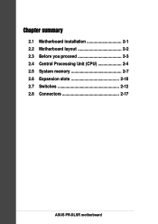
Chapter summary 2.1 Motherboard installation 2-1 2.2 Motherboard layout 2-2 2.3 Before you proceed 2-3 2.4 Central Processing Unit (CPU 2-4 2.5 System memory 2-7 2.6 Expansion slots 2-10 2.7 Switches 2-12 2.8 Connectors 2-17 ASUS PR-DLSR motherboard
Chapter summary 2.1 Motherboard installation 2-1 2.2 Motherboard layout 2-2 2.3 Before you proceed 2-3 2.4 Central Processing Unit (CPU 2-4 2.5 System memory 2-7 2.6 Expansion slots 2-10 2.7 Switches 2-12 2.8 Connectors 2-17 ASUS PR-DLSR motherboard

PR-DLSR User Manual
Page 25
...measures 12 x 12 inches (30.5 x 30.5 cm). Make sure to the chassis. Place this side towards the rear of the chassis ASUS PR-DLSR motherboard user guide 2-1 Failure to ensure that the motherboard fits into it into the holes indicated by circles to secure the motherboard to unplug the... power cord before installing or removing the motherboard. The PR-DLSR uses the extended ATX form factor that you install the motherboard, study the configuration of the chassis as indicated in the image below....
...measures 12 x 12 inches (30.5 x 30.5 cm). Make sure to the chassis. Place this side towards the rear of the chassis ASUS PR-DLSR motherboard user guide 2-1 Failure to ensure that the motherboard fits into it into the holes indicated by circles to secure the motherboard to unplug the... power cord before installing or removing the motherboard. The PR-DLSR uses the extended ATX form factor that you install the motherboard, study the configuration of the chassis as indicated in the image below....
PR-DLSR User Manual
Page 27
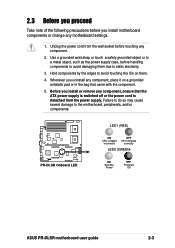
... them . 4. Before you install or remove any component, ensure that came with the component. 5. PR-DLSR ® PR-DLSR Onboard LED LED1 (RED) ON CPU installed incorrectly OFF CPU installed correctly LED2 (GREEN) ON Standby Power OFF Powered Off ASUS PR-DLSR motherboard user guide 2-3 Use a grounded wrist strap or touch a safely grounded object or to a metal...
... them . 4. Before you install or remove any component, ensure that came with the component. 5. PR-DLSR ® PR-DLSR Onboard LED LED1 (RED) ON CPU installed incorrectly OFF CPU installed correctly LED2 (GREEN) ON Standby Power OFF Powered Off ASUS PR-DLSR motherboard user guide 2-3 Use a grounded wrist strap or touch a safely grounded object or to a metal...
PR-DLSR User Manual
Page 29
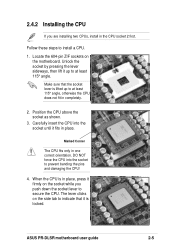
... at least 115° angle. Make sure that it fits in the CPU socket 2 first. Carefully insert the CPU into the socket to install a CPU. 1. ASUS PR-DLSR motherboard user guide 2-5 Follow these steps to prevent bending the pins and damaging the CPU! 4. When the CPU is locked. Marked Corner The CPU fits...
... at least 115° angle. Make sure that it fits in the CPU socket 2 first. Carefully insert the CPU into the socket to install a CPU. 1. ASUS PR-DLSR motherboard user guide 2-5 Follow these steps to prevent bending the pins and damaging the CPU! 4. When the CPU is locked. Marked Corner The CPU fits...

PR-DLSR User Manual
Page 31
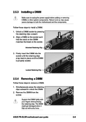
... SDRAM technology evolved from the mainstream PC66, PC100, PC133 memory known as an SDR DIMM, but it fits in a socket specially designed for DDR DIMMs. ASUS PR-DLSR motherboard user guide 2-7 DO NOT force a DIMM into a socket to the 168-pin of SDR memory. Also, a DDR DIMM is single notched while an SDR... Memory Module (DIMM) sockets. 2.5 System memory 2.5.1 Overview The motherboard comes with Serial Presence Detect (SPD) and Error Check and Correction (ECC). 104 Pins 80 Pins PR-DLSR ® PR-DLSR 184-Pin DDR DIMM Sockets A DDR DIMM is double notched.
... SDRAM technology evolved from the mainstream PC66, PC100, PC133 memory known as an SDR DIMM, but it fits in a socket specially designed for DDR DIMMs. ASUS PR-DLSR motherboard user guide 2-7 DO NOT force a DIMM into a socket to the 168-pin of SDR memory. Also, a DDR DIMM is single notched while an SDR... Memory Module (DIMM) sockets. 2.5 System memory 2.5.1 Overview The motherboard comes with Serial Presence Detect (SPD) and Error Check and Correction (ECC). 104 Pins 80 Pins PR-DLSR ® PR-DLSR 184-Pin DDR DIMM Sockets A DDR DIMM is double notched.
PR-DLSR User Manual
Page 33
ASUS PR-DLSR motherboard user guide 2-9 Unlocked Retaining Clip 3. Remove the DIMM from the socket. Support the DIMM lightly with extra force. Follow these steps to remove a DIMM. 1. ...
ASUS PR-DLSR motherboard user guide 2-9 Unlocked Retaining Clip 3. Remove the DIMM from the socket. Support the DIMM lightly with extra force. Follow these steps to remove a DIMM. 1. ...
PR-DLSR User Manual
Page 35
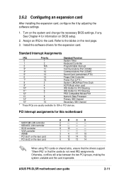
... an IRQ to the tables on BIOS setup. 2. 2.6.2 Configuring an expansion card After installing the expansion card, configure the it by adjusting the software settings. 1. ASUS PR-DLSR motherboard user guide 2-11 Otherwise, conflicts will arise between the two PCI groups, making the system unstable and the card inoperable. See Chapter 4 for this...
... an IRQ to the tables on BIOS setup. 2. 2.6.2 Configuring an expansion card After installing the expansion card, configure the it by adjusting the software settings. 1. ASUS PR-DLSR motherboard user guide 2-11 Otherwise, conflicts will arise between the two PCI groups, making the system unstable and the card inoperable. See Chapter 4 for this...

PR-DLSR User Manual
Page 37
... The option to set the frequency multiple between the CPU internal and external frequencies. If you to set in conjunction with the CPU Bus Frequency. ASUS PR-DLSR motherboard user guide 2-13 CPU Core:Bus frequency multiple (SW2 Switches 1-8) These switches allow you are using a locked CPU, setting the switches does not produce...
... The option to set the frequency multiple between the CPU internal and external frequencies. If you to set in conjunction with the CPU Bus Frequency. ASUS PR-DLSR motherboard user guide 2-13 CPU Core:Bus frequency multiple (SW2 Switches 1-8) These switches allow you are using a locked CPU, setting the switches does not produce...
PR-DLSR User Manual
Page 39
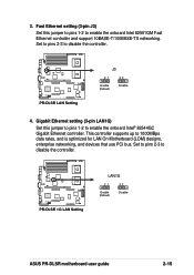
... pins 2-3 to enable the onboard Intel 82551QM Fast Ethernet controller and support 10BASE-T/100BASE-TX networking. PR-DLSR ® PR-DLSR LAN Setting J3 21 32 Enable (Default) Disable 4. PR-DLSR ® PR-DLSR 1G LAN Setting LAN1G 21 Enable (Default) 32 Disable ASUS PR-DLSR motherboard user guide 2-15 Gigabit Ethernet setting (3-pin LAN1G) Set this jumper to pins 1-2 to...
... pins 2-3 to enable the onboard Intel 82551QM Fast Ethernet controller and support 10BASE-T/100BASE-TX networking. PR-DLSR ® PR-DLSR LAN Setting J3 21 32 Enable (Default) Disable 4. PR-DLSR ® PR-DLSR 1G LAN Setting LAN1G 21 Enable (Default) 32 Disable ASUS PR-DLSR motherboard user guide 2-15 Gigabit Ethernet setting (3-pin LAN1G) Set this jumper to pins 1-2 to...
PR-DLSR User Manual
Page 41
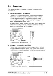
... detection feature. If you remove any chassis component, the sensor triggers and sends a high-level signal to record a chassis intrusion event. COM2 PIN 1 PR-DLSR ® PR-DLSR Serial COM2 Connector ASUS PR-DLSR motherboard user guide 2-17 Chassis alarm lead (4-1 pin CHASSIS) This lead is for a chassis designed with a jumper cap. 2.8 Connectors This section describes and...this connector then install the bracket into a slot opening at the back of the system chassis. CHASSIS +5Volt (Power Supply Stand By) Chassis Signal Ground PR-DLSR ® PR-DLSR Chassis Open Alarm Lead 2.
... detection feature. If you remove any chassis component, the sensor triggers and sends a high-level signal to record a chassis intrusion event. COM2 PIN 1 PR-DLSR ® PR-DLSR Serial COM2 Connector ASUS PR-DLSR motherboard user guide 2-17 Chassis alarm lead (4-1 pin CHASSIS) This lead is for a chassis designed with a jumper cap. 2.8 Connectors This section describes and...this connector then install the bracket into a slot opening at the back of the system chassis. CHASSIS +5Volt (Power Supply Stand By) Chassis Signal Ground PR-DLSR ® PR-DLSR Chassis Open Alarm Lead 2.
PR-DLSR User Manual
Page 43
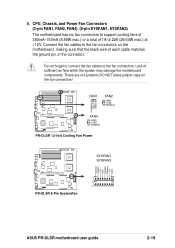
... connector. 5. These are not jumpers! FAN1 FAN2 GND +12V Rotation GND +12V Rotation PR-DLSR ® FAN4 GND +12V Rotation PR-DLSR 12-Volt Cooling Fan Power SYSFAN1 SYSFAN2 Rotation Rotation +12V GND Rotation Rotation +12V GND 1 PR-DLSR 1 ® PR-DLSR 8-Pin SystemFan ASUS PR-DLSR motherboard user guide 2-19 Do not forget to connect the fan cables to support...
... connector. 5. These are not jumpers! FAN1 FAN2 GND +12V Rotation GND +12V Rotation PR-DLSR ® FAN4 GND +12V Rotation PR-DLSR 12-Volt Cooling Fan Power SYSFAN1 SYSFAN2 Rotation Rotation +12V GND Rotation Rotation +12V GND 1 PR-DLSR 1 ® PR-DLSR 8-Pin SystemFan ASUS PR-DLSR motherboard user guide 2-19 Do not forget to connect the fan cables to support...

PR-DLSR User Manual
Page 45
The backplane connectors support two kinds of a SCSI card. BRIDGE-AR12 BPCON (MB) BPCON (BP) BRIDGE/S-AR12 PR-DLSR ® PR-DLSR BPCON Connectors SCSI connector (underneath) 8. 7. The BRIDGE-AR12 is the standard bridge board the links various functions and ...backplane bridge board that you to the backplane. The BRIDGE/S-AR12 functions similarly but, in the future.) ASMB-HE ASMB-LE PR-DLSR ® PR-DLSR ASMB Connectors ASUS PR-DLSR motherboard user guide 2-21 Server management board connectors (eRMC) These connectors allows you may purchase in addition, allows connection of...
The backplane connectors support two kinds of a SCSI card. BRIDGE-AR12 BPCON (MB) BPCON (BP) BRIDGE/S-AR12 PR-DLSR ® PR-DLSR BPCON Connectors SCSI connector (underneath) 8. 7. The BRIDGE-AR12 is the standard bridge board the links various functions and ...backplane bridge board that you to the backplane. The BRIDGE/S-AR12 functions similarly but, in the future.) ASMB-HE ASMB-LE PR-DLSR ® PR-DLSR ASMB Connectors ASUS PR-DLSR motherboard user guide 2-21 Server management board connectors (eRMC) These connectors allows you may purchase in addition, allows connection of...
PR-DLSR User Manual
Page 48
Chapter summary 3.1 Starting up for the first time 3-1 3.2 Powering off the computer 3-2 ASUS PR-DLSR motherboard
Chapter summary 3.1 Starting up for the first time 3-1 3.2 Powering off the computer 3-2 ASUS PR-DLSR motherboard
PR-DLSR User Manual
Page 49
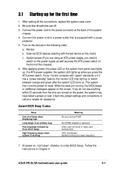
... the instructions in the following order: a. For ATX power supplies, the system LED lights up when you turned on the front of the system chassis. 4. ASUS PR-DLSR motherboard user guide 3-1 Connect the power cord to switch on the power supply as well as press the ATX power switch on the power, the...
... the instructions in the following order: a. For ATX power supplies, the system LED lights up when you turned on the front of the system chassis. 4. ASUS PR-DLSR motherboard user guide 3-1 Connect the power cord to switch on the power supply as well as press the ATX power switch on the power, the...


