
PR-DLSR User Manual
Page 6
... that may cause undesired operation. This equipment generates, uses and can be determined by turning the equipment off and on a circuit different from digital apparatus set out in a residential installation. FCC/CDC statements Federal Communications Commission Statement This device complies with Canadian ICES-003. vi
... that may cause undesired operation. This equipment generates, uses and can be determined by turning the equipment off and on a circuit different from digital apparatus set out in a residential installation. FCC/CDC statements Federal Communications Commission Statement This device complies with Canadian ICES-003. vi

PR-DLSR User Manual
Page 7
..., disconnect all power cables from the existing system before you are unplugged before using , contact your local power company. • If the power supply is set to the correct voltage in any damage, contact your dealer immediately. • To avoid short circuits, keep paper clips, screws, and staples away from connectors...
..., disconnect all power cables from the existing system before you are unplugged before using , contact your local power company. • If the power supply is set to the correct voltage in any damage, contact your dealer immediately. • To avoid short circuits, keep paper clips, screws, and staples away from connectors...
PR-DLSR User Manual
Page 8
..., and connectors on the motherboard. • Chapter 3: Powering up This chapter describes the power up sequence and gives information on the ASUS PR-DLSR motherboard. It includes description of the BIOS parameters are also provided. • Chapter 5: OS Installation This chapter tells how to perform ...to install SCSI, LAN, and VGA drivers for various operating systems. viii It includes brief descriptions of the special attributes of the PR-DLSR motherboard. How this guide This user guide contains detailed information on the BIOS beep codes. • Chapter 4: BIOS setup This ...
..., and connectors on the motherboard. • Chapter 3: Powering up This chapter describes the power up sequence and gives information on the ASUS PR-DLSR motherboard. It includes description of the BIOS parameters are also provided. • Chapter 5: OS Installation This chapter tells how to perform ...to install SCSI, LAN, and VGA drivers for various operating systems. viii It includes brief descriptions of the special attributes of the PR-DLSR motherboard. How this guide This user guide contains detailed information on the BIOS beep codes. • Chapter 4: BIOS setup This ...
PR-DLSR User Manual
Page 16
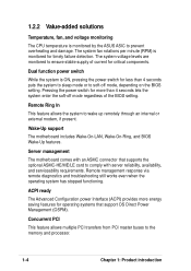
...per minute (RPM) is monitored for operating systems that supports the optional ASMC-HE/ME/LE card to soft-off mode, depending on the BIOS setting. Remote Ring In This feature allows the system to the memory and processor. 1-4 Chapter 1: Product introduction Server management The motherboard comes with an ... to wake up remotely through an internal or external modem, if present. Dual function power switch While the system is monitored by the ASUS ASIC to ensure stable supply of the BIOS setting. Pressing the power switch for more energy saving features for timely failure detection.
...per minute (RPM) is monitored for operating systems that supports the optional ASMC-HE/ME/LE card to soft-off mode, depending on the BIOS setting. Remote Ring In This feature allows the system to the memory and processor. 1-4 Chapter 1: Product introduction Server management The motherboard comes with an ... to wake up remotely through an internal or external modem, if present. Dual function power switch While the system is monitored by the ASUS ASIC to ensure stable supply of the BIOS setting. Pressing the power switch for more energy saving features for timely failure detection.
PR-DLSR User Manual
Page 20
...-X2 supports 64-bit PCI/PCI-X I/O buses that allows large, efficient, and flexible I /O subsystem, which supports multiple PCI/PCI-X interfaces that comply with up to set the CPU external frequency. 7 24-pin ATX power connector. This 5-switch Dual Inline Package (DIP) allows you to 133MHz. 3 DDR DIMM sockets. The Champion I/O Bridge...
...-X2 supports 64-bit PCI/PCI-X I/O buses that allows large, efficient, and flexible I /O subsystem, which supports multiple PCI/PCI-X interfaces that comply with up to set the CPU external frequency. 7 24-pin ATX power connector. This 5-switch Dual Inline Package (DIP) allows you to 133MHz. 3 DDR DIMM sockets. The Champion I/O Bridge...
PR-DLSR User Manual
Page 27
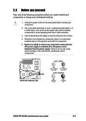
... it on them due to a metal object, such as the power supply case, before touching any motherboard settings. 1. PR-DLSR ® PR-DLSR Onboard LED LED1 (RED) ON CPU installed incorrectly OFF CPU installed correctly LED2 (GREEN) ON Standby Power OFF Powered Off ASUS PR-DLSR motherboard user guide 2-3 Before you install motherboard components or change any component. 2.
... it on them due to a metal object, such as the power supply case, before touching any motherboard settings. 1. PR-DLSR ® PR-DLSR Onboard LED LED1 (RED) ON CPU installed incorrectly OFF CPU installed correctly LED2 (GREEN) ON Standby Power OFF Powered Off ASUS PR-DLSR motherboard user guide 2-3 Before you install motherboard components or change any component. 2.
PR-DLSR User Manual
Page 34
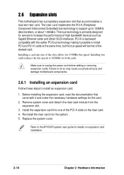
... SCSI interfaces. Before installing the expansion card, read the documentation that came with the earlier PCI bus technology making it and make the necessary hardware settings for both cards. This bus technology is backward compatible with it possible to unplug the power cord before adding or removing expansion cards. Failure to...
... SCSI interfaces. Before installing the expansion card, read the documentation that came with the earlier PCI bus technology making it and make the necessary hardware settings for both cards. This bus technology is backward compatible with it possible to unplug the power cord before adding or removing expansion cards. Failure to...
PR-DLSR User Manual
Page 35
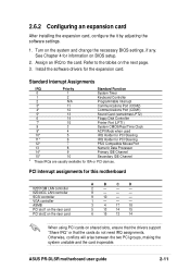
... any. 2.6.2 Configuring an expansion card After installing the expansion card, configure the it by adjusting the software settings. 1. PCI interrupt assignments for information on the next page. 3. ASUS PR-DLSR motherboard user guide 2-11 Install the software drivers for ISA or PCI devices. Turn on shared slots, ensure that the drivers support "Share IRQ...
... any. 2.6.2 Configuring an expansion card After installing the expansion card, configure the it by adjusting the software settings. 1. PCI interrupt assignments for information on the next page. 3. ASUS PR-DLSR motherboard user guide 2-11 Install the software drivers for ISA or PCI devices. Turn on shared slots, ensure that the drivers support "Share IRQ...
PR-DLSR User Manual
Page 36
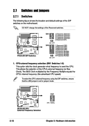
DO NOT change the settings of the CPU's external frequency (or Bus Clock). This allows the selection of the Reserved switches. PR-DLSR ® PR-DLSR DIP Switches SW1 ON 12345 1.Frequency Selection 2.Frequency Selection 3.Frequency Selection 4.Frequency Selection 5.Reserved (ON) ON...CPU speed). 2.7 Switches and jumpers 2.7.1 Switches The following figure shows the location and default settings of the DIP switches on the motherboard. SW1 ON 12345 PR-DLSR ® PR-DLSR CPU External Frequency Selection CPU 100MHz 2-12 Chapter 2: Hardware information CPU external frequency selection ...
DO NOT change the settings of the CPU's external frequency (or Bus Clock). This allows the selection of the Reserved switches. PR-DLSR ® PR-DLSR DIP Switches SW1 ON 12345 1.Frequency Selection 2.Frequency Selection 3.Frequency Selection 4.Frequency Selection 5.Reserved (ON) ON...CPU speed). 2.7 Switches and jumpers 2.7.1 Switches The following figure shows the location and default settings of the DIP switches on the motherboard. SW1 ON 12345 PR-DLSR ® PR-DLSR CPU External Frequency Selection CPU 100MHz 2-12 Chapter 2: Hardware information CPU external frequency selection ...

PR-DLSR User Manual
Page 37
... using a locked CPU, setting the switches does not produce any effect. SW2 ON 12345678 ON 12345678 ON 12345678 ON 12345678 15x 17x 20x 21x ON 12345678 ON 12345678 ON 12345678 PR-DLSR ® PR-DLSR CPU Frequency Multiple Selection 22x 23x 24x The option to set in conjunction with the CPU Bus Frequency. ASUS PR-DLSR motherboard user guide...
... using a locked CPU, setting the switches does not produce any effect. SW2 ON 12345678 ON 12345678 ON 12345678 ON 12345678 15x 17x 20x 21x ON 12345678 ON 12345678 ON 12345678 PR-DLSR ® PR-DLSR CPU Frequency Multiple Selection 22x 23x 24x The option to set in conjunction with the CPU Bus Frequency. ASUS PR-DLSR motherboard user guide...
PR-DLSR User Manual
Page 38
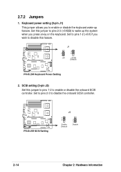
...) PR-DLSR ® PR-DLSR Keyboard Power Setting 2. PR-DLSR ® PR-DLSR SCSI Setting J5 1 2 Enable (Default) 2 3 Disable 2-14 Chapter 2: Hardware information 2.7.2 Jumpers 1. Set this jumper to pins 2-3 (+5VSB) to wake up feature. Set to pins 2-3 to enable or disable the onboard SCSI controller. Keyboard power setting (3-pin J1) This jumper allows you press a key on the keyboard. SCSI setting (3-pin J5) Set this...
...) PR-DLSR ® PR-DLSR Keyboard Power Setting 2. PR-DLSR ® PR-DLSR SCSI Setting J5 1 2 Enable (Default) 2 3 Disable 2-14 Chapter 2: Hardware information 2.7.2 Jumpers 1. Set this jumper to pins 2-3 (+5VSB) to wake up feature. Set to pins 2-3 to enable or disable the onboard SCSI controller. Keyboard power setting (3-pin J1) This jumper allows you press a key on the keyboard. SCSI setting (3-pin J5) Set this...
PR-DLSR User Manual
Page 39
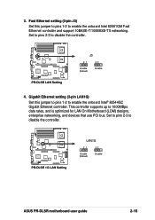
... (LOM) designs, enterprise networking, and devices that use PCI bus. PR-DLSR ® PR-DLSR 1G LAN Setting LAN1G 21 Enable (Default) 32 Disable ASUS PR-DLSR motherboard user guide 2-15 This controller supports up to disable the controller. PR-DLSR ® PR-DLSR LAN Setting J3 21 32 Enable (Default) Disable 4. 3. Set to pins 2-3 to enable the onboard Intel® 82544GC Gigabit Ethernet...
... (LOM) designs, enterprise networking, and devices that use PCI bus. PR-DLSR ® PR-DLSR 1G LAN Setting LAN1G 21 Enable (Default) 32 Disable ASUS PR-DLSR motherboard user guide 2-15 This controller supports up to disable the controller. PR-DLSR ® PR-DLSR LAN Setting J3 21 32 Enable (Default) Disable 4. 3. Set to pins 2-3 to enable the onboard Intel® 82544GC Gigabit Ethernet...
PR-DLSR User Manual
Page 49
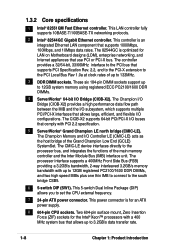
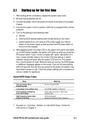
... are using an ATX power supply, you press the ATX power switch. 3.1 Starting up . Follow the instructions in the following order: a. ASUS PR-DLSR motherboard user guide 3-1 Award BIOS Beep Codes Beep One short beep when displaying logo Long beeps in an endless loop One long beep followed by...the ATX power switch on the chain) c. System power (if you turned on test. After making all switches are off. 3. Check the jumper settings and connections or call your monitor complies with "green" standards or if it has a "power standby" feature, the monitor LED may have failed ...
... are using an ATX power supply, you press the ATX power switch. 3.1 Starting up . Follow the instructions in the following order: a. ASUS PR-DLSR motherboard user guide 3-1 Award BIOS Beep Codes Beep One short beep when displaying logo Long beeps in an endless loop One long beep followed by...the ATX power switch on the chain) c. System power (if you turned on test. After making all switches are off. 3. Check the jumper settings and connections or call your monitor complies with "green" standards or if it has a "power standby" feature, the monitor LED may have failed ...
PR-DLSR User Manual
Page 51
BIOS setup Detailed descriptions of the BIOS parameters are also provided. Chapter 4 This chapter tells how to change system settings through the BIOS Setup menus.
BIOS setup Detailed descriptions of the BIOS parameters are also provided. Chapter 4 This chapter tells how to change system settings through the BIOS Setup menus.
PR-DLSR User Manual
Page 57
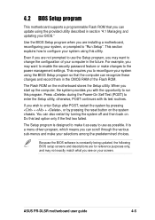
...you wish to reconfigure your system using the BIOS Setup program so that you may want to change the configuration of the Flash ROM. ASUS PR-DLSR motherboard user guide 4-5 For example, you can update using this utility. The Setup program is designed to make it as easy to ...the first two failed. This section explains how to enter the Setup utility, otherwise, POST continues with the opportunity to the power management settings. The Flash ROM on the system chassis. It is constantly being updated, the following BIOS setup screens and descriptions are for reference purposes ...
...you wish to reconfigure your system using the BIOS Setup program so that you may want to change the configuration of the Flash ROM. ASUS PR-DLSR motherboard user guide 4-5 For example, you can update using this utility. The Setup program is designed to make it as easy to ...the first two failed. This section explains how to enter the Setup utility, otherwise, POST continues with the opportunity to the power management settings. The Flash ROM on the system chassis. It is constantly being updated, the following BIOS setup screens and descriptions are for reference purposes ...
PR-DLSR User Manual
Page 58
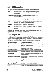
SERVER Use this menu to set server-related items EXIT Use this menu to exit the current menu or to configure power management features. POWER Use this menu to enable and ...
SERVER Use this menu to set server-related items EXIT Use this menu to exit the current menu or to configure power management features. POWER Use this menu to enable and ...
PR-DLSR User Manual
Page 59
... field. Use the key to return to field within a menu. ASUS PR-DLSR motherboard user guide 4-7 The General Help screen lists the legend keys and their corresponding functions. Scroll bar When a scroll bar appears to the right of the fields, use the set default hot key to the left ) appears to load the Setup...
... field. Use the key to return to field within a menu. ASUS PR-DLSR motherboard user guide 4-7 The General Help screen lists the legend keys and their corresponding functions. Scroll bar When a scroll bar appears to the right of the fields, use the set default hot key to the left ) appears to load the Setup...

PR-DLSR User Manual
Page 60
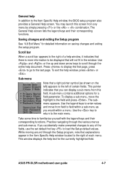
...Day: (1 to 31), Year: (up to 59). The Floppy 3 Mode feature allows reading and writing of floppy drive installed. System Time [XX:XX:XX] Sets the system to the date that you specify (usually the current time). Legacy Diskette A [1.44M, 3.5 in .] Floppy 3 Mode Support [Disabled] This is ...None] [360K, 5.25 in.] [1.2M , 5.25 in.] [720K , 3.5 in.] [1.44M, 3.5 in.] [2.88M, 3.5 in .] Sets the type of 1.2MB (as opposed to support older Japanese floppy drives. System Date [XX/XX/XXXX] Sets the system to the time that you enter the Setup program, the following screen appears. The format...
...Day: (1 to 31), Year: (up to 59). The Floppy 3 Mode feature allows reading and writing of floppy drive installed. System Time [XX:XX:XX] Sets the system to the date that you specify (usually the current time). Legacy Diskette A [1.44M, 3.5 in .] Floppy 3 Mode Support [Disabled] This is ...None] [360K, 5.25 in.] [1.2M , 5.25 in.] [720K , 3.5 in.] [1.44M, 3.5 in.] [2.88M, 3.5 in .] Sets the type of 1.2MB (as opposed to support older Japanese floppy drives. System Date [XX/XX/XXXX] Sets the system to the time that you enter the Setup program, the following screen appears. The format...
PR-DLSR User Manual
Page 61
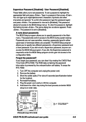
...Setup program and to gain full access to the configuration fields. If you did , the Supervisor password is set to Clear CMOS PR-DLSR ® PR-DLSR Clear RTC RAM ASUS PR-DLSR motherboard user guide 4-9 Remove the battery. 3. Plug the power cord and turn ON the computer. 6.... If you did not set to eight alphanumeric characters. Re-install the battery. 5. CR2032 3V Lithium Cell CMOS Power J7 ...
...Setup program and to gain full access to the configuration fields. If you did , the Supervisor password is set to Clear CMOS PR-DLSR ® PR-DLSR Clear RTC RAM ASUS PR-DLSR motherboard user guide 4-9 Remove the battery. 3. Plug the power cord and turn ON the computer. 6.... If you did not set to eight alphanumeric characters. Re-install the battery. 5. CR2032 3V Lithium Cell CMOS Power J7 ...
PR-DLSR User Manual
Page 62
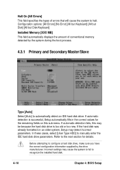
... Memory [XXX MB] This field automatically displays the amount of errors that will cause the system to automatically detect an IDE hard disk drive. Incorrect settings may detect incorrect parameters. Halt On [All Errors] This field specifies the types of conventional memory detected by the drive manufacturer.
... Memory [XXX MB] This field automatically displays the amount of errors that will cause the system to automatically detect an IDE hard disk drive. Incorrect settings may detect incorrect parameters. Halt On [All Errors] This field specifies the types of conventional memory detected by the drive manufacturer.