
PR-DLSR User Manual
Page 8
...and connectors on the motherboard. • Chapter 3: Powering up This chapter describes the power up sequence and gives information on the ASUS PR-DLSR motherboard. It includes brief descriptions of the special attributes of the BIOS parameters are also provided. • Chapter 5: OS Installation This... chapter tells how to perform when installing system components. It includes description of the PR-DLSR motherboard. How this guide This user guide contains detailed information on the BIOS beep codes. • Chapter 4: BIOS setup This...
...and connectors on the motherboard. • Chapter 3: Powering up This chapter describes the power up sequence and gives information on the ASUS PR-DLSR motherboard. It includes brief descriptions of the special attributes of the BIOS parameters are also provided. • Chapter 5: OS Installation This... chapter tells how to perform when installing system components. It includes description of the PR-DLSR motherboard. How this guide This user guide contains detailed information on the BIOS beep codes. • Chapter 4: BIOS setup This...
PR-DLSR User Manual
Page 13
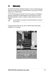
... ServerWorks® Grand Champion Low End (GCLE) SystemSet to deliver a reliable and high performance server platform. ASUS PR-DLSR motherboard user guide 1-1 1.1 Welcome! The PR-DLSR supports dual Intel® Xeon™ processors in the 1U system. The PR-DLSR is pre-installed in the long line of new features and latest technologies making it another standout...
... ServerWorks® Grand Champion Low End (GCLE) SystemSet to deliver a reliable and high performance server platform. ASUS PR-DLSR motherboard user guide 1-1 1.1 Welcome! The PR-DLSR supports dual Intel® Xeon™ processors in the 1U system. The PR-DLSR is pre-installed in the long line of new features and latest technologies making it another standout...

PR-DLSR User Manual
Page 15
Integrated IDE bridge The motherboard includes two connectors to provide onboard video solution. The IDE connectors support Ultra DMA 66/33, PIO modes 3 & 4 devices. ASUS PR-DLSR motherboard user guide 1-3 Onboard VGA The ATI Rage-XL PCI-based VGA controller integrates an 8MB display SDRAM to support an IDE board with dual-channel bus master IDE connectors.
Integrated IDE bridge The motherboard includes two connectors to provide onboard video solution. The IDE connectors support Ultra DMA 66/33, PIO modes 3 & 4 devices. ASUS PR-DLSR motherboard user guide 1-3 Onboard VGA The ATI Rage-XL PCI-based VGA controller integrates an 8MB display SDRAM to support an IDE board with dual-channel bus master IDE connectors.
PR-DLSR User Manual
Page 17
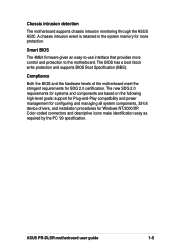
... icons make identification easy as required by the PC '99 specification. Chassis intrusion detection The motherboard supports chassis intrusion monitoring through the ASUS ASIC. A chassis intrusion event is retained in the system memory for more control and protection to the motherboard. The BIOS has ... management for configuring and managing all system components, 32-bit device drivers, and installation procedures for SDG 2.0 certification. ASUS PR-DLSR motherboard user guide 1-5 Smart BIOS The 4Mbit firmware gives an easy-to-use interface that provides more protection.
... icons make identification easy as required by the PC '99 specification. Chassis intrusion detection The motherboard supports chassis intrusion monitoring through the ASUS ASIC. A chassis intrusion event is retained in the system memory for more control and protection to the motherboard. The BIOS has ... management for configuring and managing all system components, 32-bit device drivers, and installation procedures for SDG 2.0 certification. ASUS PR-DLSR motherboard user guide 1-5 Smart BIOS The 4Mbit firmware gives an easy-to-use interface that provides more protection.
PR-DLSR User Manual
Page 19
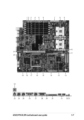
12 3 4 5 6 7 89 10 21 11 20 19 18 17 16 15 14 13 12 22 23 24 25 26 27 28 29 30 31 32 33 ASUS PR-DLSR motherboard user guide 1-7
12 3 4 5 6 7 89 10 21 11 20 19 18 17 16 15 14 13 12 22 23 24 25 26 27 28 29 30 31 32 33 ASUS PR-DLSR motherboard user guide 1-7
PR-DLSR User Manual
Page 21
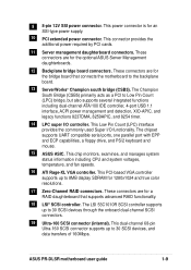
...supports up to 8MB display SDRAM for a RAID daughterboard that connects the motherboard to 30 SCSI devices, and data transfers of 160Mbps. ASUS PR-DLSR motherboard user guide 1-9 This Low Pin Count (LPC) interface provides the commonly used Super I /O controller. The chipset supports UART ...controller supports up to the backplane board. 13 ServerWorks® Champion south bridge (CSB5). This power connector is for the optional ASUS Server Management daughterboards. 12 Backplane bridge board connectors. The LSI 53C1010R SCSI controller supports up to Low Pin Count (LPC) bridge...
...supports up to 8MB display SDRAM for a RAID daughterboard that connects the motherboard to 30 SCSI devices, and data transfers of 160Mbps. ASUS PR-DLSR motherboard user guide 1-9 This Low Pin Count (LPC) interface provides the commonly used Super I /O controller. The chipset supports UART ...controller supports up to the backplane board. 13 ServerWorks® Champion south bridge (CSB5). This power connector is for the optional ASUS Server Management daughterboards. 12 Backplane bridge board connectors. The LSI 53C1010R SCSI controller supports up to Low Pin Count (LPC) bridge...
PR-DLSR User Manual
Page 24
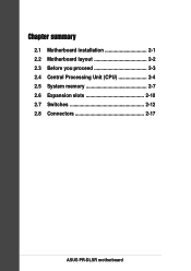
Chapter summary 2.1 Motherboard installation 2-1 2.2 Motherboard layout 2-2 2.3 Before you proceed 2-3 2.4 Central Processing Unit (CPU 2-4 2.5 System memory 2-7 2.6 Expansion slots 2-10 2.7 Switches 2-12 2.8 Connectors 2-17 ASUS PR-DLSR motherboard
Chapter summary 2.1 Motherboard installation 2-1 2.2 Motherboard layout 2-2 2.3 Before you proceed 2-3 2.4 Central Processing Unit (CPU 2-4 2.5 System memory 2-7 2.6 Expansion slots 2-10 2.7 Switches 2-12 2.8 Connectors 2-17 ASUS PR-DLSR motherboard

PR-DLSR User Manual
Page 25
... in the image below. 2.1.2 Screw holes Place seven (7) screws into the chassis in the correct orientation. Place this side towards the rear of the chassis ASUS PR-DLSR motherboard user guide 2-1 The edge with external ports goes to do so may damage the motherboard. Do not overtighten the screws! The... PR-DLSR uses the extended ATX form factor that the motherboard fits into it into the holes indicated by circles to secure the motherboard to unplug the ...
... in the image below. 2.1.2 Screw holes Place seven (7) screws into the chassis in the correct orientation. Place this side towards the rear of the chassis ASUS PR-DLSR motherboard user guide 2-1 The edge with external ports goes to do so may damage the motherboard. Do not overtighten the screws! The... PR-DLSR uses the extended ATX form factor that the motherboard fits into it into the holes indicated by circles to secure the motherboard to unplug the ...
PR-DLSR User Manual
Page 27
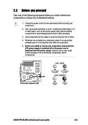
... off or the power cord is detached from the wall socket before touching any component. 2. PR-DLSR ® PR-DLSR Onboard LED LED1 (RED) ON CPU installed incorrectly OFF CPU installed correctly LED2 (GREEN) ON Standby Power OFF Powered Off ASUS PR-DLSR motherboard user guide 2-3 Hold components by the edges to static electricity. 3. Use a grounded wrist...
... off or the power cord is detached from the wall socket before touching any component. 2. PR-DLSR ® PR-DLSR Onboard LED LED1 (RED) ON CPU installed incorrectly OFF CPU installed correctly LED2 (GREEN) ON Standby Power OFF Powered Off ASUS PR-DLSR motherboard user guide 2-3 Hold components by the edges to static electricity. 3. Use a grounded wrist...
PR-DLSR User Manual
Page 29
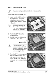
... does not fit in place. Locate the 604-pin ZIF sockets on the socket while you are installing two CPUs, install in one correct orientation. ASUS PR-DLSR motherboard user guide 2-5 Unlock the socket by pressing the lever sideways, then lift it fits in completely. 2. Carefully insert the CPU into the socket to...
... does not fit in place. Locate the 604-pin ZIF sockets on the socket while you are installing two CPUs, install in one correct orientation. ASUS PR-DLSR motherboard user guide 2-5 Unlock the socket by pressing the lever sideways, then lift it fits in completely. 2. Carefully insert the CPU into the socket to...

PR-DLSR User Manual
Page 31
... using 184-pin registered PC2100/1600 DDR DIMMs with Serial Presence Detect (SPD) and Error Check and Correction (ECC). 104 Pins 80 Pins PR-DLSR ® PR-DLSR 184-Pin DDR DIMM Sockets A DDR DIMM is keyed with six Double Data Rate (DDR) Dual Inline Memory Module (DIMM) sockets. DO...evolved from the mainstream PC66, PC100, PC133 memory known as an SDR DIMM, but it fits in a socket specially designed for DDR DIMMs. ASUS PR-DLSR motherboard user guide 2-7 DDR Data Transfer Rate 266MHz 200MHz DDR Base Frequency 133MHz 100MHz A DDR DIMM has the same physical dimensions as Single Data...
... using 184-pin registered PC2100/1600 DDR DIMMs with Serial Presence Detect (SPD) and Error Check and Correction (ECC). 104 Pins 80 Pins PR-DLSR ® PR-DLSR 184-Pin DDR DIMM Sockets A DDR DIMM is keyed with six Double Data Rate (DDR) Dual Inline Memory Module (DIMM) sockets. DO...evolved from the mainstream PC66, PC100, PC133 memory known as an SDR DIMM, but it fits in a socket specially designed for DDR DIMMs. ASUS PR-DLSR motherboard user guide 2-7 DDR Data Transfer Rate 266MHz 200MHz DDR Base Frequency 133MHz 100MHz A DDR DIMM has the same physical dimensions as Single Data...
PR-DLSR User Manual
Page 33
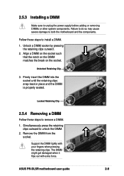
... DIMM is properly seated. Follow these steps to remove a DIMM. 1. Locked Retaining Clip 2.5.4 Removing a DIMM Follow these steps to both the motherboard and the components. ASUS PR-DLSR motherboard user guide 2-9 2.5.3 Installing a DIMM Make sure to unlock the DIMM. 2. Failure to do so may cause severe damage to install a DIMM. 1. Support the DIMM...
... DIMM is properly seated. Follow these steps to remove a DIMM. 1. Locked Retaining Clip 2.5.4 Removing a DIMM Follow these steps to both the motherboard and the components. ASUS PR-DLSR motherboard user guide 2-9 2.5.3 Installing a DIMM Make sure to unlock the DIMM. 2. Failure to do so may cause severe damage to install a DIMM. 1. Support the DIMM...
PR-DLSR User Manual
Page 35
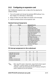
... that the cards do not need IRQ assignments. Otherwise, conflicts will arise between the two PCI groups, making the system unstable and the card inoperable. ASUS PR-DLSR motherboard user guide 2-11 Install the software drivers for ISA or PCI devices. Standard Interrupt Assignments IRQ Priority Standard Function 0 1 System Timer 1 2 Keyboard Controller 2 N/A Programmable...
... that the cards do not need IRQ assignments. Otherwise, conflicts will arise between the two PCI groups, making the system unstable and the card inoperable. ASUS PR-DLSR motherboard user guide 2-11 Install the software drivers for ISA or PCI devices. Standard Interrupt Assignments IRQ Priority Standard Function 0 1 System Timer 1 2 Keyboard Controller 2 N/A Programmable...

PR-DLSR User Manual
Page 37
... ON 12345678 ON 12345678 15x 17x 20x 21x ON 12345678 ON 12345678 ON 12345678 PR-DLSR ® PR-DLSR CPU Frequency Multiple Selection 22x 23x 24x The option to set the frequency multiple between the CPU internal and external frequencies. ASUS PR-DLSR motherboard user guide 2-13 2. CPU Core:Bus frequency multiple (SW2 Switches 1-8) These switches allow...
... ON 12345678 ON 12345678 15x 17x 20x 21x ON 12345678 ON 12345678 ON 12345678 PR-DLSR ® PR-DLSR CPU Frequency Multiple Selection 22x 23x 24x The option to set the frequency multiple between the CPU internal and external frequencies. ASUS PR-DLSR motherboard user guide 2-13 2. CPU Core:Bus frequency multiple (SW2 Switches 1-8) These switches allow...
PR-DLSR User Manual
Page 39
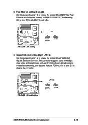
... J3) Set this jumper to pins 1-2 to enable the onboard Intel® 82544GC Gigabit Ethernet controller. PR-DLSR ® PR-DLSR LAN Setting J3 21 32 Enable (Default) Disable 4. PR-DLSR ® PR-DLSR 1G LAN Setting LAN1G 21 Enable (Default) 32 Disable ASUS PR-DLSR motherboard user guide 2-15 3. Gigabit Ethernet setting (3-pin LAN1G) Set this jumper to pins 1-2 to...
... J3) Set this jumper to pins 1-2 to enable the onboard Intel® 82544GC Gigabit Ethernet controller. PR-DLSR ® PR-DLSR LAN Setting J3 21 32 Enable (Default) Disable 4. PR-DLSR ® PR-DLSR 1G LAN Setting LAN1G 21 Enable (Default) 32 Disable ASUS PR-DLSR motherboard user guide 2-15 3. Gigabit Ethernet setting (3-pin LAN1G) Set this jumper to pins 1-2 to...
PR-DLSR User Manual
Page 41
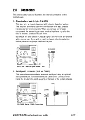
...connector then install the bracket into a slot opening at the back of the system chassis. COM2 PIN 1 PR-DLSR ® PR-DLSR Serial COM2 Connector ASUS PR-DLSR motherboard user guide 2-17 When you wish to record a chassis intrusion event. CHASSIS +5Volt (Power Supply... Stand By) Chassis Signal Ground PR-DLSR ® PR-DLSR Chassis Open Alarm Lead 2. 2.8 Connectors This section describes and illustrates the internal connectors ...
...connector then install the bracket into a slot opening at the back of the system chassis. COM2 PIN 1 PR-DLSR ® PR-DLSR Serial COM2 Connector ASUS PR-DLSR motherboard user guide 2-17 When you wish to record a chassis intrusion event. CHASSIS +5Volt (Power Supply... Stand By) Chassis Signal Ground PR-DLSR ® PR-DLSR Chassis Open Alarm Lead 2. 2.8 Connectors This section describes and illustrates the internal connectors ...
PR-DLSR User Manual
Page 43
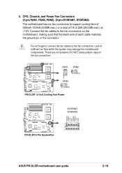
... sure that the black wire of each cable matches the ground pin of the connector. FAN1 FAN2 GND +12V Rotation GND +12V Rotation PR-DLSR ® FAN4 GND +12V Rotation PR-DLSR 12-Volt Cooling Fan Power SYSFAN1 SYSFAN2 Rotation Rotation +12V GND Rotation Rotation +12V GND 1 PR-DLSR 1 ® PR-DLSR 8-Pin SystemFan ASUS PR-DLSR motherboard user guide 2-19 5.
... sure that the black wire of each cable matches the ground pin of the connector. FAN1 FAN2 GND +12V Rotation GND +12V Rotation PR-DLSR ® FAN4 GND +12V Rotation PR-DLSR 12-Volt Cooling Fan Power SYSFAN1 SYSFAN2 Rotation Rotation +12V GND Rotation Rotation +12V GND 1 PR-DLSR 1 ® PR-DLSR 8-Pin SystemFan ASUS PR-DLSR motherboard user guide 2-19 5.

PR-DLSR User Manual
Page 45
7. The BRIDGE/S-AR12 functions similarly but, in the future.) ASMB-HE ASMB-LE PR-DLSR ® PR-DLSR ASMB Connectors ASUS PR-DLSR motherboard user guide 2-21 BRIDGE-AR12 BPCON (MB) BPCON (BP) BRIDGE/S-AR12 PR-DLSR ® PR-DLSR BPCON Connectors SCSI connector (underneath) 8. The BRIDGE-AR12 is the standard bridge board the links various functions and signals from the motherboard...
7. The BRIDGE/S-AR12 functions similarly but, in the future.) ASMB-HE ASMB-LE PR-DLSR ® PR-DLSR ASMB Connectors ASUS PR-DLSR motherboard user guide 2-21 BRIDGE-AR12 BPCON (MB) BPCON (BP) BRIDGE/S-AR12 PR-DLSR ® PR-DLSR BPCON Connectors SCSI connector (underneath) 8. The BRIDGE-AR12 is the standard bridge board the links various functions and signals from the motherboard...
PR-DLSR User Manual
Page 48
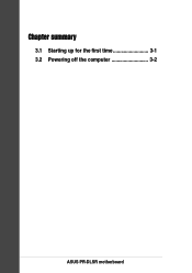
Chapter summary 3.1 Starting up for the first time 3-1 3.2 Powering off the computer 3-2 ASUS PR-DLSR motherboard
Chapter summary 3.1 Starting up for the first time 3-1 3.2 Powering off the computer 3-2 ASUS PR-DLSR motherboard
PR-DLSR User Manual
Page 49
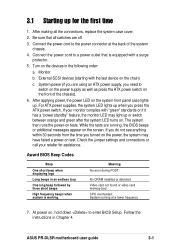
... POST No DRAM installed or detected Video card not found or video card memory bad CPU overheated; Connect the power cord to enter BIOS Setup. ASUS PR-DLSR motherboard user guide 3-1 Turn on tests. After applying power, the power LED on , hold down to a power outlet that all the connections, replace the system...
... POST No DRAM installed or detected Video card not found or video card memory bad CPU overheated; Connect the power cord to enter BIOS Setup. ASUS PR-DLSR motherboard user guide 3-1 Turn on tests. After applying power, the power LED on , hold down to a power outlet that all the connections, replace the system...


