User Manual
Page 31
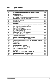
...65533;�S�B�9�1�0��; �U�S�B��1�1�1�2��) 16. Clear RTC RAM (3-pin CLRTC) 21. ATX P��o�w�e�r��c�o�n�n�e�c�t�o�rs&#... 2-33 2-13 2-10 2-22 2-23 2-24 2-25 2-14 2-22 2-34 2-27 2-12 2-26 2-25 2-30 2-21 2-10 2-28 2-28 2-30 ASUS P9X79 WS 2-3 System panel connector (20-8 pin PANEL) 15. LGA2011 CPU Socket 4. 2.2.2 Layout contents Connectors/Jumpers/Switches/Slots 1.
...65533;�S�B�9�1�0��; �U�S�B��1�1�1�2��) 16. Clear RTC RAM (3-pin CLRTC) 21. ATX P��o�w�e�r��c�o�n�n�e�c�t�o�rs&#... 2-33 2-13 2-10 2-22 2-23 2-24 2-25 2-14 2-22 2-34 2-27 2-12 2-26 2-25 2-30 2-21 2-10 2-28 2-28 2-30 ASUS P9X79 WS 2-3 System panel connector (20-8 pin PANEL) 15. LGA2011 CPU Socket 4. 2.2.2 Layout contents Connectors/Jumpers/Switches/Slots 1.
User Manual
Page 49
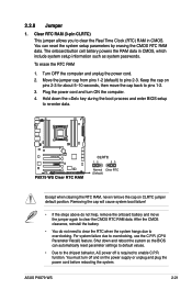
Clear RTC RAM (3-pin CLRTC) This jumper allows you to enable C.P.R. You can automatically reset parameter settings to default values. • Due to the chipset behavior, AC power off and on CLRTC jumper default position. For system failure due to pins 2-3. ASUS P9X79 WS 2-21 Turn OFF the computer and unplug ... BIOS setup to overclocking. Hold down and reboot the system so the BIOS can reset the system setup parameters by erasing the CMOS RTC RAM data. Keep the cap on pins 2-3 for about 5-10 seconds, then move the jumper again to pins 1-2. 3. Removing the cap ...
Clear RTC RAM (3-pin CLRTC) This jumper allows you to enable C.P.R. You can automatically reset parameter settings to default values. • Due to the chipset behavior, AC power off and on CLRTC jumper default position. For system failure due to pins 2-3. ASUS P9X79 WS 2-21 Turn OFF the computer and unplug ... BIOS setup to overclocking. Hold down and reboot the system so the BIOS can reset the system setup parameters by erasing the CMOS RTC RAM data. Keep the cap on pins 2-3 for about 5-10 seconds, then move the jumper again to pins 1-2. 3. Removing the cap ...
User Manual
Page 81
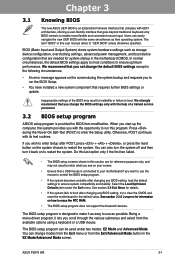
... setup program is connected to your screen. • Ensure that a USB mouse is designed to boot. Chapter 3 ASUS P9X79 WS 3-1 In normal circumstances, the default BIOS settings apply to most conditions to erase the RTC RAM. • The BIOS setup program does not support the bluetooth devices. Otherwise, POST continues with UEFI architecture, offering...
... setup program is connected to your screen. • Ensure that a USB mouse is designed to boot. Chapter 3 ASUS P9X79 WS 3-1 In normal circumstances, the default BIOS settings apply to most conditions to erase the RTC RAM. • The BIOS setup program does not support the bluetooth devices. Otherwise, POST continues with UEFI architecture, offering...

User Manual
Page 85
... Main\ Security > Advanced Password Description If ONLY the Administrator's password is set , then this is only asked for information on how to erase the RTC RAM. • The Administrator or User Password items on password and must be entered to Setup and is a power on top of the BIOS Setup program... characters long. UEFI BIOS Utility - UEFI BIOS Utility - In Setup the User will have forgotten your BIOS password, erase the CMOS Real Time Clock (RTC) RAM to change the system security settings. Chapter 3 ASUS P9X79 WS 3-5
... Main\ Security > Advanced Password Description If ONLY the Administrator's password is set , then this is only asked for information on how to erase the RTC RAM. • The Administrator or User Password items on password and must be entered to Setup and is a power on top of the BIOS Setup program... characters long. UEFI BIOS Utility - UEFI BIOS Utility - In Setup the User will have forgotten your BIOS password, erase the CMOS Real Time Clock (RTC) RAM to change the system security settings. Chapter 3 ASUS P9X79 WS 3-5


