
User Guide
Page 1
P9D-E/4L Motherboard
P9D-E/4L Motherboard

User Guide
Page 3
... guide...x How this guide is organized x Where to find more information x P9D-E/4L Specifications Summary xii Chapter 1: Product Introduction 1.1 Welcome!...1-3 1.2 Package contents 1-3 1.3 Serial number label 1-4 1.4 Special features 1-4 1.4.1 Product highlights 1-4 1.4.2 Innovative ASUS features 1-6 Chapter 2: Hardware Information 2.1 Before you proceed 2-3 2.2 Motherboard overview 2-4 2.2.1 Placement direction 2-4 2.2.2 Screw holes 2-4 2.2.3 Motherboard layout 2-5 2.2.4 Layout contents 2-6 2.3 Central Processing Unit (CPU 2-8 2.3.1 Installing the CPU...
... guide...x How this guide is organized x Where to find more information x P9D-E/4L Specifications Summary xii Chapter 1: Product Introduction 1.1 Welcome!...1-3 1.2 Package contents 1-3 1.3 Serial number label 1-4 1.4 Special features 1-4 1.4.1 Product highlights 1-4 1.4.2 Innovative ASUS features 1-6 Chapter 2: Hardware Information 2.1 Before you proceed 2-3 2.2 Motherboard overview 2-4 2.2.1 Placement direction 2-4 2.2.2 Screw holes 2-4 2.2.3 Motherboard layout 2-5 2.2.4 Layout contents 2-6 2.3 Central Processing Unit (CPU 2-8 2.3.1 Installing the CPU...

User Guide
Page 8
...read all cables are correctly connected and the power cables are using an adapter or extension cord. DO NOT throw the motherboard in municipal waste. These devices could interrupt the grounding circuit. • Make sure that your retailer. Operation safety • Before installing... a qualified service technician or your dealer immediately. • To avoid short circuits, keep paper clips, screws, and staples away from the motherboard, ensure that all power cables from the existing system before using , contact your local power company. • If the power supply is set...
...read all cables are correctly connected and the power cables are using an adapter or extension cord. DO NOT throw the motherboard in municipal waste. These devices could interrupt the grounding circuit. • Make sure that your retailer. Operation safety • Before installing... a qualified service technician or your dealer immediately. • To avoid short circuits, keep paper clips, screws, and staples away from the motherboard, ensure that all power cables from the existing system before using , contact your local power company. • If the power supply is set...

User Guide
Page 10
... through the BIOS Setup menus. How this guide This user guide contains the information you have been added by your dealer. ASUS websites The ASUS website provides updated information on the motherboard. • Chapter 3: Powering up This chapter describes the power up , creating, and configuring RAID sets using the available utilities. • Chapter...
... through the BIOS Setup menus. How this guide This user guide contains the information you have been added by your dealer. ASUS websites The ASUS website provides updated information on the motherboard. • Chapter 3: Powering up This chapter describes the power up , creating, and configuring RAID sets using the available utilities. • Chapter...

User Guide
Page 16
This chapter contains the following sections: 1.1 Welcome!...1-3 1.2 Package contents 1-3 1.3 Serial number label 1-4 1.4 Special features 1-4 ASUS P9D-E/4L Chapter summary 1 This chapter describes the motherboard features and the new technologies it supports.
This chapter contains the following sections: 1.1 Welcome!...1-3 1.2 Package contents 1-3 1.3 Serial number label 1-4 1.4 Special features 1-4 ASUS P9D-E/4L Chapter summary 1 This chapter describes the motherboard features and the new technologies it supports.

User Guide
Page 17
... provides KVM over IP solution Discrete 8-channel audio card provides clearest high quality sounds ASUS P9D-E/4L 1-3 Items Standard Gift Box Pack SATA DOM Power cable SATA 3G cable SATA 6G cable COM port cable Support CD ASWM Enterprise SDVD Motherboard User Guide Metal Plate for LGA1150 1 1 2 4 1 1 1 1 1 1...the items in the long line of the above items is damaged or missing, contact your motherboard package for buying an ASUS® P9D-E/4L motherboard! Thank you start installing the motherboard and hardware devices on it another standout in your package with the list below. 1.2 ...
... provides KVM over IP solution Discrete 8-channel audio card provides clearest high quality sounds ASUS P9D-E/4L 1-3 Items Standard Gift Box Pack SATA DOM Power cable SATA 3G cable SATA 6G cable COM port cable Support CD ASWM Enterprise SDVD Motherboard User Guide Metal Plate for LGA1150 1 1 2 4 1 1 1 1 1 1...the items in the long line of the above items is damaged or missing, contact your motherboard package for buying an ASUS® P9D-E/4L motherboard! Thank you start installing the motherboard and hardware devices on it another standout in your package with the list below. 1.2 ...

User Guide
Page 18
...from the ASUS Technical Support team, you must take note of the motherboard's serial number containing 12 characters xxS2xxxxxxxx shown as the figure below its power, current, and temperature specification limits. The Intel® EM64T feature allows your problems. P9D-E/4L xxS2xxxxxxxx Made... in China 合格 1.4 Special features 1.4.1 Product highlights Latest processor technology This motherboard supports the latest Intel® Xeon® Processor E3-1200 v3/ ...
...from the ASUS Technical Support team, you must take note of the motherboard's serial number containing 12 characters xxS2xxxxxxxx shown as the figure below its power, current, and temperature specification limits. The Intel® EM64T feature allows your problems. P9D-E/4L xxS2xxxxxxxx Made... in China 合格 1.4 Special features 1.4.1 Product highlights Latest processor technology This motherboard supports the latest Intel® Xeon® Processor E3-1200 v3/ ...

User Guide
Page 19
..., and Hot Swap. The Serial ATA II specification provides twice the bandwidth of PCIe 2.0. USB 2.0 technology The motherboard implements the Universal Serial Bus (USB) 2.0 specification that provides twice the performance and speed of the current Serial...Gigabit LAN controllers and ports which provide a total solution for your networking needs. Serial ATA II technology The motherboard supports the Serial ATA II 3 Gb/s technology through the Serial ATA interface and Intel® C224 chipset...with its complete backward compatibility to prevent overheating and damage. ASUS P9D-E/4L 1-5
..., and Hot Swap. The Serial ATA II specification provides twice the bandwidth of PCIe 2.0. USB 2.0 technology The motherboard implements the Universal Serial Bus (USB) 2.0 specification that provides twice the performance and speed of the current Serial...Gigabit LAN controllers and ports which provide a total solution for your networking needs. Serial ATA II technology The motherboard supports the Serial ATA II 3 Gb/s technology through the Serial ATA interface and Intel® C224 chipset...with its complete backward compatibility to prevent overheating and damage. ASUS P9D-E/4L 1-5

User Guide
Page 22
It includes description of the jumpers and connectors on the motherboard. This chapter contains the following sections: 2.1 Before you have to perform when installing system components. Chapter summary 2 This chapter lists the hardware setup procedures that you proceed 2-3 2.2 Motherboard overview 2-4 2.3 Central Processing Unit (CPU 2-8 2.4 System memory 2-14 2.5 Expansion slots 2-16 2.6 Onboard LEDs 2-23 2.7 Jumpers...2-26 2.8 Connectors 2-29 ASUS P9D-E/4L
It includes description of the jumpers and connectors on the motherboard. This chapter contains the following sections: 2.1 Before you have to perform when installing system components. Chapter summary 2 This chapter lists the hardware setup procedures that you proceed 2-3 2.2 Motherboard overview 2-4 2.3 Central Processing Unit (CPU 2-8 2.4 System memory 2-14 2.5 Expansion slots 2-16 2.6 Onboard LEDs 2-23 2.7 Jumpers...2-26 2.8 Connectors 2-29 ASUS P9D-E/4L

User Guide
Page 23
... from the wall socket before handling components to avoid damaging them due to static electricity. • Hold components by the edges to the motherboard, peripherals, and/or components. ASUS P9D-E/4L 2-3 Failure to do so may cause severe damage to avoid touching the ICs on them. • Whenever you uninstall any component, place it...
... from the wall socket before handling components to avoid damaging them due to static electricity. • Hold components by the edges to the motherboard, peripherals, and/or components. ASUS P9D-E/4L 2-3 Failure to do so may cause severe damage to avoid touching the ICs on them. • Whenever you uninstall any component, place it...

User Guide
Page 24
...an ATX 1.1 compliant chassis. Ensure to do so can damage the motherboard. DO NOT overtighten the screws! 2.2 Motherboard overview Before you install the motherboard, study the configuration of your chassis to ensure that the motherboard fits into it into the holes indicated by circles to secure the... motherboard to the chassis. The edge with external ports goes to the rear part of the chassis 2-4 Chapter 2: Hardware information Failure to unplug the chassis power cord before installing or removing the motherboard. Doing so can cause you ...
...an ATX 1.1 compliant chassis. Ensure to do so can damage the motherboard. DO NOT overtighten the screws! 2.2 Motherboard overview Before you install the motherboard, study the configuration of your chassis to ensure that the motherboard fits into it into the holes indicated by circles to secure the... motherboard to the chassis. The edge with external ports goes to the rear part of the chassis 2-4 Chapter 2: Hardware information Failure to unplug the chassis power cord before installing or removing the motherboard. Doing so can cause you ...

User Guide
Page 25
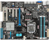
2.2.3 Motherboard layout ASUS P9D-E/4L 2-5
2.2.3 Motherboard layout ASUS P9D-E/4L 2-5

User Guide
Page 28
... product warranty does not cover damage to the PnP cap/socket contacts/motherboard components. ASUS will shoulder the cost of the PnP cap. 2.3.1 Installing the CPU To install the CPU: 1. ASUS will process Return Merchandise Authorization (RMA) requests only if the motherboard comes with a surface mount LGA1150 socket designed for the Intel® Xeon...
... product warranty does not cover damage to the PnP cap/socket contacts/motherboard components. ASUS will shoulder the cost of the PnP cap. 2.3.1 Installing the CPU To install the CPU: 1. ASUS will process Return Merchandise Authorization (RMA) requests only if the motherboard comes with a surface mount LGA1150 socket designed for the Intel® Xeon...

User Guide
Page 31
... and fan assembly in size and dimension. ASUS P9D-E/4L 2-11 A B A A B B A Orient the heatsink and fan assembly such that the CPU fan cable is incompatible with CPU fan. • Use an LGA1150-compatible CPU heatsink and CPU fan assembly only. Ensure that you have installed the motherboard to the chassis before you install the... the CPU fan and heatsink assembly. If you purchased a separate CPU heatsink and fan assembly, ensure that the four fasteners B match the holes on the motherboard. 2.
... and fan assembly in size and dimension. ASUS P9D-E/4L 2-11 A B A A B B A Orient the heatsink and fan assembly such that the CPU fan cable is incompatible with CPU fan. • Use an LGA1150-compatible CPU heatsink and CPU fan assembly only. Ensure that you have installed the motherboard to the chassis before you install the... the CPU fan and heatsink assembly. If you purchased a separate CPU heatsink and fan assembly, ensure that the four fasteners B match the holes on the motherboard. 2.

User Guide
Page 32
... fan cable to connect the CPU fan connector! B 3. Hardware monitoring errors can occur if you fail to disengage the heatsink and fan assembly from the motherboard. Carefully remove the heatsink and fan assembly from the connector on the motherboard labeled CPU_FAN1. A B A A B B A 4. DO NOT forget to the connector on the...
... fan cable to connect the CPU fan connector! B 3. Hardware monitoring errors can occur if you fail to disengage the heatsink and fan assembly from the motherboard. Carefully remove the heatsink and fan assembly from the connector on the motherboard labeled CPU_FAN1. A B A A B B A 4. DO NOT forget to the connector on the...

User Guide
Page 33
... using the recommended sequence below. ASUS P9D-E/4L 2-13 Peel off the sticker on the heatsink metal plate and affix the plate to the back of the CPU before installing the heatsink and fan. 1. A C D B A C D B • Ensure that you have applied the thermal interface material to the top of the motherboard, matching the standoffs to...
... using the recommended sequence below. ASUS P9D-E/4L 2-13 Peel off the sticker on the heatsink metal plate and affix the plate to the back of the CPU before installing the heatsink and fan. 1. A C D B A C D B • Ensure that you have applied the thermal interface material to the top of the motherboard, matching the standoffs to...

User Guide
Page 34
... 3 (DDR3) Dual Inline Memory Modules (DIMM) sockets. For optimum compatibility, it is notched differently to prevent installation on a DDR2 DIMM socket. 2.4 System memory 2.4.1 Overview The motherboard comes with the same CAS latency.
... 3 (DDR3) Dual Inline Memory Modules (DIMM) sockets. For optimum compatibility, it is notched differently to prevent installation on a DDR2 DIMM socket. 2.4 System memory 2.4.1 Overview The motherboard comes with the same CAS latency.

User Guide
Page 35
... of the DIMM simultaneously until the retaining 3 clip snaps back into the socket. Locked Retaining Clip Always insert the DIMM into a socket in the motherboard package. • Refer to the user guide for qualified vendor lists of the DIMM. Removing a DIMM from the socket. 2 1 Support the...Align a DIMM on the socket such that 1 the notch on the DIMM matches the DIMM slot key on a single clip DIMM socket 1. ASUS P9D-E/4L 2-15 Press the retaining clip outward to ensure proper sitting of the memory modules. The DIMM might get damaged when it fits in any further...
... of the DIMM simultaneously until the retaining 3 clip snaps back into the socket. Locked Retaining Clip Always insert the DIMM into a socket in the motherboard package. • Refer to the user guide for qualified vendor lists of the DIMM. Removing a DIMM from the socket. 2 1 Support the...Align a DIMM on the socket such that 1 the notch on the DIMM matches the DIMM slot key on a single clip DIMM socket 1. ASUS P9D-E/4L 2-15 Press the retaining clip outward to ensure proper sitting of the memory modules. The DIMM might get damaged when it fits in any further...

User Guide
Page 36
... make the necessary hardware settings for later use . 2.5 Expansion slots In the future, you may cause you physical injury and damage motherboard components. 2.5.1 Installing an expansion card To install an expansion card: 1. The following subsections describe the slots and the expansion cards that... use . 4. Before installing the expansion card, read the documentation that you removed earlier. 6. Remove the system unit cover (if your motherboard is completely seated on BIOS setup. 2. See Chapter 4 for the expansion card. When using PCI cards on shared slots, ensure that ...
... make the necessary hardware settings for later use . 2.5 Expansion slots In the future, you may cause you physical injury and damage motherboard components. 2.5.1 Installing an expansion card To install an expansion card: 1. The following subsections describe the slots and the expansion cards that... use . 4. Before installing the expansion card, read the documentation that you removed earlier. 6. Remove the system unit cover (if your motherboard is completely seated on BIOS setup. 2. See Chapter 4 for the expansion card. When using PCI cards on shared slots, ensure that ...

User Guide
Page 39
...connector location. ASUS P9D-E/4L 2-19 The motherboard layout and appearance may vary depending on the PIKE RAID card slot. • The motherboard illustration is completely seated on the model, but the installation steps remain the same. • Refer to install an optional ASUS RAID card on the motherboard. 2. ...Insert the RAID card into the PIKE RAID card slot. Locate the PIKE RAID card slot on your motherboard. 1. Align the golden fingers of the RAID card with the ...
...connector location. ASUS P9D-E/4L 2-19 The motherboard layout and appearance may vary depending on the PIKE RAID card slot. • The motherboard illustration is completely seated on the model, but the installation steps remain the same. • Refer to install an optional ASUS RAID card on the motherboard. 2. ...Insert the RAID card into the PIKE RAID card slot. Locate the PIKE RAID card slot on your motherboard. 1. Align the golden fingers of the RAID card with the ...

