
User Guide
Page 16
This chapter contains the following sections: 1.1 Welcome!...1-3 1.2 Package contents 1-3 1.3 Serial number label 1-4 1.4 Special features 1-4 ASUS P9D-E/4L Chapter summary 1 This chapter describes the motherboard features and the new technologies it supports.
This chapter contains the following sections: 1.1 Welcome!...1-3 1.2 Package contents 1-3 1.3 Serial number label 1-4 1.4 Special features 1-4 ASUS P9D-E/4L Chapter summary 1 This chapter describes the motherboard features and the new technologies it supports.

User Guide
Page 17
... RAID card MARVELL 4-port SATA 6G RAID card Remote Management solution provides KVM over IP solution Discrete 8-channel audio card provides clearest high quality sounds ASUS P9D-E/4L 1-3 Items Standard Gift Box Pack SATA DOM Power cable SATA 3G cable SATA 6G cable COM port cable Support CD ASWM Enterprise SDVD Motherboard User...
... RAID card MARVELL 4-port SATA 6G RAID card Remote Management solution provides KVM over IP solution Discrete 8-channel audio card provides clearest high quality sounds ASUS P9D-E/4L 1-3 Items Standard Gift Box Pack SATA DOM Power cable SATA 3G cable SATA 6G cable COM port cable Support CD ASWM Enterprise SDVD Motherboard User...

User Guide
Page 19
... core frequency depending on USB 2.0. USB 2.0 technology The motherboard implements the Universal Serial Bus (USB) 2.0 specification that provides twice the performance and speed of PCIe 2.0. ASUS P9D-E/4L 1-5 Serial ATA III technology The motherboard supports the Serial ATA III 6 Gb/s technology through the Serial ATA interface and Intel® C224 chipset. Intel®...
... core frequency depending on USB 2.0. USB 2.0 technology The motherboard implements the Universal Serial Bus (USB) 2.0 specification that provides twice the performance and speed of PCIe 2.0. ASUS P9D-E/4L 1-5 Serial ATA III technology The motherboard supports the Serial ATA III 6 Gb/s technology through the Serial ATA interface and Intel® C224 chipset. Intel®...

User Guide
Page 22
It includes description of the jumpers and connectors on the motherboard. This chapter contains the following sections: 2.1 Before you have to perform when installing system components. Chapter summary 2 This chapter lists the hardware setup procedures that you proceed 2-3 2.2 Motherboard overview 2-4 2.3 Central Processing Unit (CPU 2-8 2.4 System memory 2-14 2.5 Expansion slots 2-16 2.6 Onboard LEDs 2-23 2.7 Jumpers...2-26 2.8 Connectors 2-29 ASUS P9D-E/4L
It includes description of the jumpers and connectors on the motherboard. This chapter contains the following sections: 2.1 Before you have to perform when installing system components. Chapter summary 2 This chapter lists the hardware setup procedures that you proceed 2-3 2.2 Motherboard overview 2-4 2.3 Central Processing Unit (CPU 2-8 2.4 System memory 2-14 2.5 Expansion slots 2-16 2.6 Onboard LEDs 2-23 2.7 Jumpers...2-26 2.8 Connectors 2-29 ASUS P9D-E/4L

User Guide
Page 23
ASUS P9D-E/4L 2-3 2.1 Before you proceed Take note of the following precautions before you install or remove any component, ensure that the power supply is switched off or ...
ASUS P9D-E/4L 2-3 2.1 Before you proceed Take note of the following precautions before you install or remove any component, ensure that the power supply is switched off or ...

User Guide
Page 25
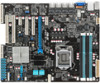
2.2.3 Motherboard layout ASUS P9D-E/4L 2-5
2.2.3 Motherboard layout ASUS P9D-E/4L 2-5

User Guide
Page 29
...-left corner of the socket. 3. Lift the load lever until it to the socket's alignment keys. Gold triangle mark Alignment key CPU notches Alignment key ASUS P9D-E/4L 2-9 Load lever Retention tab Load plate 4. 2. The CPU fits in only one orientation.
...-left corner of the socket. 3. Lift the load lever until it to the socket's alignment keys. Gold triangle mark Alignment key CPU notches Alignment key ASUS P9D-E/4L 2-9 Load lever Retention tab Load plate 4. 2. The CPU fits in only one orientation.

User Guide
Page 31
... and LGA1366 sockets in place. Push down two fasteners at a time in a diagonal sequence to the chassis before you install the heatsink and fan assembly. ASUS P9D-E/4L 2-11 2.3.2 Installing the CPU heatsink The Intel® LGA1150 processor requires a specially designed CPU heatsink to ensure optimum thermal condition and performance. • If you...
... and LGA1366 sockets in place. Push down two fasteners at a time in a diagonal sequence to the chassis before you install the heatsink and fan assembly. ASUS P9D-E/4L 2-11 2.3.2 Installing the CPU heatsink The Intel® LGA1150 processor requires a specially designed CPU heatsink to ensure optimum thermal condition and performance. • If you...

User Guide
Page 33
... that the heatsink is not skewed or tilted, otherwise the CPU will overheat. • Do not overtighten the screws. Doing so can damage the CPU. ASUS P9D-E/4L 2-13 Peel off the sticker on the heatsink metal plate and affix the plate to the back of the CPU before installing the heatsink and...
... that the heatsink is not skewed or tilted, otherwise the CPU will overheat. • Do not overtighten the screws. Doing so can damage the CPU. ASUS P9D-E/4L 2-13 Peel off the sticker on the heatsink metal plate and affix the plate to the back of the CPU before installing the heatsink and...

User Guide
Page 35
... proper sitting of the DIMM simultaneously until the retaining 3 clip snaps back into the socket. Press the retaining clip outward to avoid damaging the DIMM. 3. ASUS P9D-E/4L 2-15 Unlock a DIMM socket by both ends of the DIMM. 2.4.3 Installing a DIMM on the socket. 2 DIMM slot key Unlocked retaining clip A DIMM is keyed with...
... proper sitting of the DIMM simultaneously until the retaining 3 clip snaps back into the socket. Press the retaining clip outward to avoid damaging the DIMM. 3. ASUS P9D-E/4L 2-15 Unlock a DIMM socket by both ends of the DIMM. 2.4.3 Installing a DIMM on the socket. 2 DIMM slot key Unlocked retaining clip A DIMM is keyed with...

User Guide
Page 37
... Intel® C224 PCH. 2.5.7 PCI slot The PCI 1 and PCI 2 slots supports cards such as LAN, USB, and other cards that complies with PCI specifications. ASUS P9D-E/4L 2-17 2.5.3 Interrupt assignments Standard Interrupt assignments IRQ Priority Standard function 0 1 System Timer 1 2 Keyboard Controller 2 -
... Intel® C224 PCH. 2.5.7 PCI slot The PCI 1 and PCI 2 slots supports cards such as LAN, USB, and other cards that complies with PCI specifications. ASUS P9D-E/4L 2-17 2.5.3 Interrupt assignments Standard Interrupt assignments IRQ Priority Standard function 0 1 System Timer 1 2 Keyboard Controller 2 -

User Guide
Page 39
... the golden fingers of the RAID card with the PIKE RAID card slot. 3. Insert the RAID card into the PIKE RAID card slot. ASUS P9D-E/4L 2-19 2.5.9 Installing the ASUS PIKE RAID card Follow the steps below to section 2.8.2 Internal Connectors for reference only. Ensure that it is for the PIKE SAS/SATA connector...
... the golden fingers of the RAID card with the PIKE RAID card slot. 3. Insert the RAID card into the PIKE RAID card slot. ASUS P9D-E/4L 2-19 2.5.9 Installing the ASUS PIKE RAID card Follow the steps below to section 2.8.2 Internal Connectors for reference only. Ensure that it is for the PIKE SAS/SATA connector...

User Guide
Page 41
2.5.11 Connecting the Thermal sensor cable Follow the steps below to connect the Thermal sensor (TR1) cable to the connector on the model, but the installation steps remain the same. Connect the Thermal Sensor cable to monitor temperature. Place the other end of the Thermal Sensor cable to the device you would like to the connector. 3. The motherboard illustration is for reference only. ASUS P9D-E/4L 2-21 The motherboard layout and appearance may vary depending on your motherboard. 1. Locate the Thermal Sensor (TR1) connector on the motherboard. 2.
2.5.11 Connecting the Thermal sensor cable Follow the steps below to connect the Thermal sensor (TR1) cable to the connector on the model, but the installation steps remain the same. Connect the Thermal Sensor cable to monitor temperature. Place the other end of the Thermal Sensor cable to the device you would like to the connector. 3. The motherboard illustration is for reference only. ASUS P9D-E/4L 2-21 The motherboard layout and appearance may vary depending on your motherboard. 1. Locate the Thermal Sensor (TR1) connector on the motherboard. 2.

User Guide
Page 43
Standby Power LED (SB_PWR1) The motherboard comes with the ASUS ASMB7 management device and indicates its initiation status. The illustration below shows the location of the onboard LED. 2. The BMC LED blinks after system initiation ... or plugging in soft-off mode. The BMC LED works with a standby power LED. When the PSU is plugged and the system is working normally. ASUS P9D-E/4L 2-23 Baseboard Management Controller LED (BMC_LED1) The green heartbeat LED blinks per second to indicate that the ASMB7 is OFF...
Standby Power LED (SB_PWR1) The motherboard comes with the ASUS ASMB7 management device and indicates its initiation status. The illustration below shows the location of the onboard LED. 2. The BMC LED blinks after system initiation ... or plugging in soft-off mode. The BMC LED works with a standby power LED. When the PSU is plugged and the system is working normally. ASUS P9D-E/4L 2-23 Baseboard Management Controller LED (BMC_LED1) The green heartbeat LED blinks per second to indicate that the ASMB7 is OFF...

User Guide
Page 45
ASUS P9D-E/4L 2-25 This LED helps you visually locate the server among other servers especially when you are located at the back of the server rack. 5. Location LED (LOCLED1) The Location LED is an onboard LED that ligths up when the Location Button on the front panel is pressed.
ASUS P9D-E/4L 2-25 This LED helps you visually locate the server among other servers especially when you are located at the back of the server rack. 5. Location LED (LOCLED1) The Location LED is an onboard LED that ligths up when the Location Button on the front panel is pressed.

User Guide
Page 47
VGA controller setting (3-pin VGA_SW1) This jumper allows you to activate the Gigabit LAN feature. Set to pins 1-2 to enable or disable the onboard VGA controller. 2. Set to pins 1-2 to enable or disable the onboard Intel® I210AT Gigabit LAN controllers. ASUS P9D-E/4L 2-27 LAN controller setting (3-pin LAN_SW1, LAN_SW2, LAN_SW3, LAN_SW4) These jumpers allow you to activate the VGA feature. 3.
VGA controller setting (3-pin VGA_SW1) This jumper allows you to activate the Gigabit LAN feature. Set to pins 1-2 to enable or disable the onboard VGA controller. 2. Set to pins 1-2 to enable or disable the onboard Intel® I210AT Gigabit LAN controllers. ASUS P9D-E/4L 2-27 LAN controller setting (3-pin LAN_SW1, LAN_SW2, LAN_SW3, LAN_SW4) These jumpers allow you to activate the VGA feature. 3.

User Guide
Page 49
... No link OFF 10 Mbps connection GREEN Linked ORANGE 100 Mbps connection BLINKING Data activity GREEN 1 Gbps connection ACT/LINK SPEED LED LED LAN port ASUS P9D-E/4L 2-29 RJ-45 ports for connecting USB 3.0 devices. 2.8 Connectors 2.8.1 Rear panel connectors 1. PS/2 keyboard/mouse port (purple/green). These ports allows Gigabit connection to turn...
... No link OFF 10 Mbps connection GREEN Linked ORANGE 100 Mbps connection BLINKING Data activity GREEN 1 Gbps connection ACT/LINK SPEED LED LED LAN port ASUS P9D-E/4L 2-29 RJ-45 ports for connecting USB 3.0 devices. 2.8 Connectors 2.8.1 Rear panel connectors 1. PS/2 keyboard/mouse port (purple/green). These ports allows Gigabit connection to turn...

User Guide
Page 51
Hard disk activity LED connector (4-pin HDLED1) This LED connector is for the storage add-on card. 2. ASUS P9D-E/4L 2-31 PSAS connectors (7-pin PSAS1, PSAS2, PSAS3, PSAS4, PSAS5, PSAS6, PSAS7, PSAS8 [Light Blue]) This motherboard comes with eight (8) PIKE Serial Attached SCSI (PSAS) connectors ...
Hard disk activity LED connector (4-pin HDLED1) This LED connector is for the storage add-on card. 2. ASUS P9D-E/4L 2-31 PSAS connectors (7-pin PSAS1, PSAS2, PSAS3, PSAS4, PSAS5, PSAS6, PSAS7, PSAS8 [Light Blue]) This motherboard comes with eight (8) PIKE Serial Attached SCSI (PSAS) connectors ...

User Guide
Page 53
... fans. Thermal sensor cable connectors (3-pin TR1) This connector allows you want to the fan connectors on the fan connectors! • All connectors feature the ASUS Smart Fan technology. Insufficient air flow inside the system may damage the motherboard components. • These are not jumpers! Connect the Thermal sensor cable to... ground pin of the connector. • DO NOT forget to connect the fan cables to connect a Thermal sensor cable that you to the fan connectors. ASUS P9D-E/4L 2-33 6.
... fans. Thermal sensor cable connectors (3-pin TR1) This connector allows you want to the fan connectors on the fan connectors! • All connectors feature the ASUS Smart Fan technology. Insufficient air flow inside the system may damage the motherboard components. • These are not jumpers! Connect the Thermal sensor cable to... ground pin of the connector. • DO NOT forget to connect the fan cables to connect a Thermal sensor cable that you to the fan connectors. ASUS P9D-E/4L 2-33 6.

User Guide
Page 55
Serial port connectors (10-1 pin COM1/COM2) These connectors are for the serial COM ports. Power Supply SMBus connector (5-pin PSUSMB1) This connector allows you install the ASUS ASMB7. ASUS P9D-E/4L 2-35 This connector functions only when you to connect SMBus (System Management Bus) to the power supply unit to a slot opening at the back of these connectors, then install the module to read PSU information. Connect the serial port module cable to one of the system chassis. 10. 9. Devices communicate with an SMBus host and/or other SMBus devices using the SMBus interface.
Serial port connectors (10-1 pin COM1/COM2) These connectors are for the serial COM ports. Power Supply SMBus connector (5-pin PSUSMB1) This connector allows you install the ASUS ASMB7. ASUS P9D-E/4L 2-35 This connector functions only when you to connect SMBus (System Management Bus) to the power supply unit to a slot opening at the back of these connectors, then install the module to read PSU information. Connect the serial port module cable to one of the system chassis. 10. 9. Devices communicate with an SMBus host and/or other SMBus devices using the SMBus interface.


