
User Guide
Page 4
... menu 3-32 3.10 Updating BIOS 3-33 3.10.1 ASUS Update utility 3-34 3.10.2 ASUS EZ Flash Utility 3-37 3.10.3 ASUS CrashFree BIOS 3 utility 3-38 3.10.4 ASUS BIOS Updater 3-39 iv Contents 2.3.10 Rear panel connection 2-40 2.3.11 Audio I/O connections 2-41 2.4 Starting up for the first time 2-44 2.5 Turning off the computer 2-45 Chapter 3: BIOS setup 3.1 Knowing BIOS 3-1 3.2 BIOS setup program 3-1 3.2.1 EZ...
... menu 3-32 3.10 Updating BIOS 3-33 3.10.1 ASUS Update utility 3-34 3.10.2 ASUS EZ Flash Utility 3-37 3.10.3 ASUS CrashFree BIOS 3 utility 3-38 3.10.4 ASUS BIOS Updater 3-39 iv Contents 2.3.10 Rear panel connection 2-40 2.3.11 Audio I/O connections 2-41 2.4 Starting up for the first time 2-44 2.5 Turning off the computer 2-45 Chapter 3: BIOS setup 3.1 Knowing BIOS 3-1 3.2 BIOS setup program 3-1 3.2.1 EZ...
User Guide
Page 5
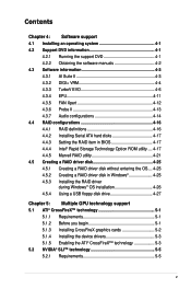
... Xpert 4-12 4.3.6 Probe II 4-13 4.3.7 Audio configurations 4-14 4.4 RAID configurations 4-16 4.4.1 RAID definitions 4-16 4.4.2 Installing Serial ATA hard disks 4-17 4.4.3 Setting the RAID item in BIOS 4-17 4.4.4 Intel® Rapid Storage Technology Option ROM utility..... 4-17 4.4.5 Marvell RAID utility 4-21 4.5 Creating a RAID driver disk 4-25 4.5.1 Creating a RAID driver disk without entering...
... Xpert 4-12 4.3.6 Probe II 4-13 4.3.7 Audio configurations 4-14 4.4 RAID configurations 4-16 4.4.1 RAID definitions 4-16 4.4.2 Installing Serial ATA hard disks 4-17 4.4.3 Setting the RAID item in BIOS 4-17 4.4.4 Intel® Rapid Storage Technology Option ROM utility..... 4-17 4.4.5 Marvell RAID utility 4-21 4.5 Creating a RAID driver disk 4-25 4.5.1 Creating a RAID driver disk without entering...
User Guide
Page 9
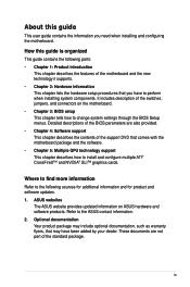
... Your product package may include optional documentation, such as warranty flyers, that you need when installing and configuring the motherboard. ASUS websites The ASUS website provides updated information on the motherboard. • Chapter 3: BIOS setup This chapter tells how to install and configure multiple ATI® CrossFireX™ and NVIDIA® SLI™...
... Your product package may include optional documentation, such as warranty flyers, that you need when installing and configuring the motherboard. ASUS websites The ASUS website provides updated information on the motherboard. • Chapter 3: BIOS setup This chapter tells how to install and configure multiple ATI® CrossFireX™ and NVIDIA® SLI™...

User Guide
Page 12
... cards support ASUS WS Diag. Jack-Sensing - MemOK! - ASUS Fan Xpert ASUS EZ DIY - ASUS CrashFree BIOS 3 - ASUS EZ Flash Utility ASUS Q-LED (CPU, DRAM, VGA, Boot Device LED) ASUS Q-Slot ASUS Q-DIMM 4 PCIe x16 slots G.P. ASUS Fanless Design: Heat-pipe solution - P8P67 WS Revolution specifications summary 1394 Audio ASUS Unique Features ASUS Q-Design Workstation Unique Features BIOS Features Back Panel I /O - ASUS Noise-Filer ASUS Digi+ VRM Utility ASUS Exclusive...
... cards support ASUS WS Diag. Jack-Sensing - MemOK! - ASUS Fan Xpert ASUS EZ DIY - ASUS CrashFree BIOS 3 - ASUS EZ Flash Utility ASUS Q-LED (CPU, DRAM, VGA, Boot Device LED) ASUS Q-Slot ASUS Q-DIMM 4 PCIe x16 slots G.P. ASUS Fanless Design: Heat-pipe solution - P8P67 WS Revolution specifications summary 1394 Audio ASUS Unique Features ASUS Q-Design Workstation Unique Features BIOS Features Back Panel I /O - ASUS Noise-Filer ASUS Digi+ VRM Utility ASUS Exclusive...

User Guide
Page 21
The Heat Pipe design is that goes beyond traditional keyboard BIOS input to enable more stable and enhances the overclocking capability. EFI BIOS(EZ Mode) Flexible, Easy BIOS Interface ASUS brand new EFI BIOS offers a user-friendly interface that the groundbreaking fanless design does not have lifetime... system more flexible and convenient mouse controls. Doing so may bend the tubing and affect the heat dissipation performance. ASUS P8P67 WS Revolution 1-5 Users can be carried away by different climate conditions in one place so you enjoy different functions without switching ...
The Heat Pipe design is that goes beyond traditional keyboard BIOS input to enable more stable and enhances the overclocking capability. EFI BIOS(EZ Mode) Flexible, Easy BIOS Interface ASUS brand new EFI BIOS offers a user-friendly interface that the groundbreaking fanless design does not have lifetime... system more flexible and convenient mouse controls. Doing so may bend the tubing and affect the heat dissipation performance. ASUS P8P67 WS Revolution 1-5 Users can be carried away by different climate conditions in one place so you enjoy different functions without switching ...
User Guide
Page 22
... Q-DIMM, and Q-Slot design speed up and simplify the DIY process! ASUS EZ-Flash Utility Simply update BIOS from a USB flash drive before entering the OS EZ Flash Utility is a user-friendly BIOS update utility. S/PDIF-out on Back I/O Port This motherboard provides convenient connectivity...experience. All of plugging in a few clicks without preparing an additional floppy diskette or using an OS-based flash utility. ASUS CrashFree BIOS 3 The ASUS CrashFree BIOS 3 allows users to external home theater audio systems via coaxial and optical S/PDIF-out (SONY-PHILIPS Digital Interface) jacks....
... Q-DIMM, and Q-Slot design speed up and simplify the DIY process! ASUS EZ-Flash Utility Simply update BIOS from a USB flash drive before entering the OS EZ Flash Utility is a user-friendly BIOS update utility. S/PDIF-out on Back I/O Port This motherboard provides convenient connectivity...experience. All of plugging in a few clicks without preparing an additional floppy diskette or using an OS-based flash utility. ASUS CrashFree BIOS 3 The ASUS CrashFree BIOS 3 allows users to external home theater audio systems via coaxial and optical S/PDIF-out (SONY-PHILIPS Digital Interface) jacks....
User Guide
Page 32
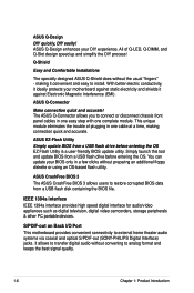
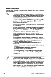
... to Intel CPU spec, CPUs with a core frequency of 2.66G support the maximum DIMM frequency of up of a higher frequency with the same CAS latency. ASUS exclusively provides two DDR3-1600 DIMM support for the dual-channel configuration. Under the default state, some memory modules for overclocking may install varying memory...
... to Intel CPU spec, CPUs with a core frequency of 2.66G support the maximum DIMM frequency of up of a higher frequency with the same CAS latency. ASUS exclusively provides two DDR3-1600 DIMM support for the dual-channel configuration. Under the default state, some memory modules for overclocking may install varying memory...
User Guide
Page 38
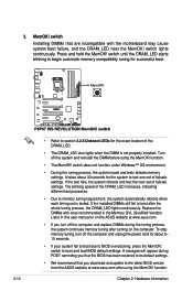
... tuning, turn off the computer and replace DIMMs during the tuning process, the system continues memory tuning after turning on the ASUS website at www.asus.com after the whole tuning process, the DRAM_LED lights continuously. A messgae will appear during POST reminding you turn off the ...MemOK! function. • The MemOK! switch Installing DIMMs that you download and update to the latest BIOS version from the ASUS website at www.asus.com. • If you that the BIOS has been restored to boot after using the MemOK! switch lights continuously. switch does not function under...
... tuning, turn off the computer and replace DIMMs during the tuning process, the system continues memory tuning after turning on the ASUS website at www.asus.com after the whole tuning process, the DRAM_LED lights continuously. A messgae will appear during POST reminding you turn off the ...MemOK! function. • The MemOK! switch Installing DIMMs that you download and update to the latest BIOS version from the ASUS website at www.asus.com. • If you that the BIOS has been restored to boot after using the MemOK! switch lights continuously. switch does not function under...

User Guide
Page 39
This user-friendly design provides an intuitive way to section 3.7.2 Boot Setting Configuration for details. 2. You may disable the POST State LEDs in sequence during motherboard booting process. POST State LEDs POST State LEDs check key components (CPU, DRAM, VGA card, and HDD) in BIOS. ASUS P8P67 WS Revolution 2-13 2.2.6 Onboard LEDs 1. TPU LED The TPU LED lights when the TPU switch is solved. Refer to locate the root problem within seconds. If an error is found, the LED next to the error device will continue lighting until the problem is turned to Enable.
This user-friendly design provides an intuitive way to section 3.7.2 Boot Setting Configuration for details. 2. You may disable the POST State LEDs in sequence during motherboard booting process. POST State LEDs POST State LEDs check key components (CPU, DRAM, VGA card, and HDD) in BIOS. ASUS P8P67 WS Revolution 2-13 2.2.6 Onboard LEDs 1. TPU LED The TPU LED lights when the TPU switch is solved. Refer to locate the root problem within seconds. If an error is found, the LED next to the error device will continue lighting until the problem is turned to Enable.
User Guide
Page 41
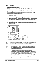
...required to pins 2-3. Hold down and reboot the system so the BIOS can clear the CMOS memory of date, time, and system setup parameters by erasing the CMOS RTC RAM data. For system failure due to re-enter data. ASUS P8P67 WS Revolution 2-15 To erase the RTC RAM 1. Except when clearing the ...RTC RAM, never remove the cap on pins 2-3 for about 5-10 seconds, then move the jumper again to pins 1-2. 3. Shut down the key during the boot process and enter BIOS setup to overclocking, use ...
...required to pins 2-3. Hold down and reboot the system so the BIOS can clear the CMOS memory of date, time, and system setup parameters by erasing the CMOS RTC RAM data. For system failure due to re-enter data. ASUS P8P67 WS Revolution 2-15 To erase the RTC RAM 1. Except when clearing the ...RTC RAM, never remove the cap on pins 2-3 for about 5-10 seconds, then move the jumper again to pins 1-2. 3. Shut down the key during the boot process and enter BIOS setup to overclocking, use ...

User Guide
Page 43
... for details. • Before creating a RAID set the SATA Mode in the motherboard support DVD. • When using Windows® XP SP3 or later versions. ASUS P8P67 WS Revolution 2-17 Refer to section 3.5.4 SATA Configuration for details. • You must install Windows® XP Service Pack 3 or later versions before using these connectors, set... only if you intend to [AHCI Mode] by default. If you are set to create a Serial ATA RAID set the SATA Mode item in the BIOS to section 4.4 RAID configurations or the manual bundled in the...
... for details. • Before creating a RAID set the SATA Mode in the motherboard support DVD. • When using Windows® XP SP3 or later versions. ASUS P8P67 WS Revolution 2-17 Refer to section 3.5.4 SATA Configuration for details. • You must install Windows® XP Service Pack 3 or later versions before using these connectors, set... only if you intend to [AHCI Mode] by default. If you are set to create a Serial ATA RAID set the SATA Mode item in the BIOS to section 4.4 RAID configurations or the manual bundled in the...
User Guide
Page 44
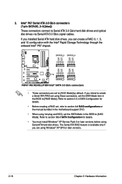
... • You must install Windows® XP Service Pack 3 or later versions before using hot-plug and NCQ, set the SATA Mode item in the BIOS to [AHCI Mode] by default. Refer to section 3.5.4 SATA Configuration for details. • Before creating a RAID set, refer to create a Serial ATA... connectors connect to [AHCI Mode]. 2. If you installed Serial ATA hard disk drives, you intend to section 4.4 RAID configurations or the manual bundled in the BIOS to Serial ATA 3.0 Gb/s hard disk drives and optical disc drives via Serial ATA 3.0 Gb/s signal cables. If you can create a RAID 0, 1, 5,...
... • You must install Windows® XP Service Pack 3 or later versions before using hot-plug and NCQ, set the SATA Mode item in the BIOS to [AHCI Mode] by default. Refer to section 3.5.4 SATA Configuration for details. • Before creating a RAID set, refer to create a Serial ATA... connectors connect to [AHCI Mode]. 2. If you installed Serial ATA hard disk drives, you intend to section 4.4 RAID configurations or the manual bundled in the BIOS to Serial ATA 3.0 Gb/s hard disk drives and optical disc drives via Serial ATA 3.0 Gb/s signal cables. If you can create a RAID 0, 1, 5,...

User Guide
Page 45
ASUS P8P67 WS Revolution 2-19 Marvell® Serial ATA 6.0 Gb/s connectors (7-pin SATA6G_E1/E2 [navy blue]) These connectors connect to Serial ATA 6.0 Gb/s hard disk drives via Serial ATA 6.0 ... 4.4.5 RAID configurations or the manual bundled in the motherboard support DVD. • When using hot-plug and NCQ, set the Marvell Controller item in the BIOS to section 3.5.6 Onboard Devices Configuration for details. 3. Refer to [AHCI Mode].
ASUS P8P67 WS Revolution 2-19 Marvell® Serial ATA 6.0 Gb/s connectors (7-pin SATA6G_E1/E2 [navy blue]) These connectors connect to Serial ATA 6.0 Gb/s hard disk drives via Serial ATA 6.0 ... 4.4.5 RAID configurations or the manual bundled in the motherboard support DVD. • When using hot-plug and NCQ, set the Marvell Controller item in the BIOS to section 3.5.6 Onboard Devices Configuration for details. 3. Refer to [AHCI Mode].

User Guide
Page 49
... is for a serial (COM) port. ASUS P8P67 WS Revolution 2-23 Connect one end of the front panel audio I /O module that you connect a high-definition front panel audio module to this connector to avail of the system chassis. By default, this connector, set the Front Panel Type item in the BIOS setup to [HD]; if you...
... is for a serial (COM) port. ASUS P8P67 WS Revolution 2-23 Connect one end of the front panel audio I /O module that you connect a high-definition front panel audio module to this connector to avail of the system chassis. By default, this connector, set the Front Panel Type item in the BIOS setup to [HD]; if you...

User Guide
Page 51
... off the power supply unit before installing the diagnosis card to OS S1 S3 S4 S5 Resume from S1 Resume from S3 Resume from S4 ASUS P8P67 WS Revolution 2-25 Locate the TPM connector (20-1 pin TPM) on the connector completely. With the LEDs of the diagnosis card facing to the PCIe slots, align... the motherboard. 2. Diagnosis card 15, 19 Initiate chip AC E0 Check and wake up AP 03 98 Detect PS2 mouse/keyboard 04 97 Initiate VGA BIOS 05 9A-9D USB initiation 10 A2 Detect IDE 30 B2 Initiate option ROM 40 OS in PIC mode OS in APIC mode Leave...
... off the power supply unit before installing the diagnosis card to OS S1 S3 S4 S5 Resume from S1 Resume from S3 Resume from S4 ASUS P8P67 WS Revolution 2-25 Locate the TPM connector (20-1 pin TPM) on the connector completely. With the LEDs of the diagnosis card facing to the PCIe slots, align... the motherboard. 2. Diagnosis card 15, 19 Initiate chip AC E0 Check and wake up AP 03 98 Detect PS2 mouse/keyboard 04 97 Initiate VGA BIOS 05 9A-9D USB initiation 10 A2 Detect IDE 30 B2 Initiate option ROM 40 OS in PIC mode OS in APIC mode Leave...

User Guide
Page 53
... IDE LED lights up when you to the HDD. • System warning speaker (4-pin SPEAKER) This 4-pin connector is for the system power button. ASUS P8P67 WS Revolution 2-27 The speaker allows you turn on the system power, and blinks when the system is in sleep or soft-off button (2-pin PWRSW) This... connector is for the HDD Activity LED. Pressing the power button turns the system on the BIOS settings. Connect the HDD Activity LED cable to this connector. Pressing the power switch for more than four seconds while the system is ON ...
... IDE LED lights up when you to the HDD. • System warning speaker (4-pin SPEAKER) This 4-pin connector is for the system power button. ASUS P8P67 WS Revolution 2-27 The speaker allows you turn on the system power, and blinks when the system is in sleep or soft-off button (2-pin PWRSW) This... connector is for the HDD Activity LED. Pressing the power button turns the system on the BIOS settings. Connect the HDD Activity LED cable to this connector. Pressing the power switch for more than four seconds while the system is ON ...

User Guide
Page 70
... One continuous beep followed by three No VGA detected short beeps One continuous beep followed by four Hardware component failure short beeps 7. BIOS Beep Description One short beep VGA detected Quick boot set to the power connector at the back of the system chassis. 4. Check ... that all the connections, replace the system case cover. 2. If you do not see anything within 30 seconds from orange to enter the BIOS Setup. Follow the instructions in the following order: a. 2.4 Starting up . External SCSI devices (starting with ATX power supplies, the system ...
... One continuous beep followed by three No VGA detected short beeps One continuous beep followed by four Hardware component failure short beeps 7. BIOS Beep Description One short beep VGA detected Quick boot set to the power connector at the back of the system chassis. 4. Check ... that all the connections, replace the system case cover. 2. If you do not see anything within 30 seconds from orange to enter the BIOS Setup. Follow the instructions in the following order: a. 2.4 Starting up . External SCSI devices (starting with ATX power supplies, the system ...

User Guide
Page 71
Pressing the power switch for more than four seconds puts the system on the BIOS setting. 2.5 Turning off the computer While the system is ON, pressing the power switch for less than four seconds lets the system enter the soft-off mode, depending on sleep mode or soft-off mode regardless of the BIOS setting. Refer to section 3.7 Power Menu for details. ASUS P8P67 WS Revolution 2-45
Pressing the power switch for more than four seconds puts the system on the BIOS setting. 2.5 Turning off the computer While the system is ON, pressing the power switch for less than four seconds lets the system enter the soft-off mode, depending on sleep mode or soft-off mode regardless of the BIOS setting. Refer to section 3.7 Power Menu for details. ASUS P8P67 WS Revolution 2-45

User Guide
Page 73
Detailed descriptions of the BIOS parameters are also provided. This chapter tells how to change the BIOS se3tup system settings through the BIOS Setup menus.
Detailed descriptions of the BIOS parameters are also provided. This chapter tells how to change the BIOS se3tup system settings through the BIOS Setup menus.

User Guide
Page 74
Chapter summary 3 3.1 Managing and updating your BIOS 3-1 3.2 BIOS setup program 3-7 3.3 Main menu 3-10 3.4....A.i .T.w.e.a.ke.r.�m.�.e�.n�.u 3-15 3.5 Advanced menu 3-22 3.6 Power menu 3-29 3.7 Boot menu 3-34 3.8 Tools menu 3-38 3.9 Exit menu 3-42 ASUS P8P67 WS Revolution
Chapter summary 3 3.1 Managing and updating your BIOS 3-1 3.2 BIOS setup program 3-7 3.3 Main menu 3-10 3.4....A.i .T.w.e.a.ke.r.�m.�.e�.n�.u 3-15 3.5 Advanced menu 3-22 3.6 Power menu 3-29 3.7 Boot menu 3-34 3.8 Tools menu 3-38 3.9 Exit menu 3-42 ASUS P8P67 WS Revolution


