
User Manual
Page 12
...Welcome! Before you for the following items. Motherboard Cables Accessories Application DVD Documentation ASUS P8P67 LX motherboard 2 x Serial ATA 6.0Gb/s cables 1 x I/O shield ASUS motherboard support DVD User Manual If any of ASUS quality motherboards! Thank you start installing the motherboard, and hardware devices on it ...the long line of the above items is damaged or missing, contact your motherboard package for buying an ASUS® P8P67 LX motherboard! The motherboard delivers a host of new features and latest technologies, making it , check the items in the...
...Welcome! Before you for the following items. Motherboard Cables Accessories Application DVD Documentation ASUS P8P67 LX motherboard 2 x Serial ATA 6.0Gb/s cables 1 x I/O shield ASUS motherboard support DVD User Manual If any of ASUS quality motherboards! Thank you start installing the motherboard, and hardware devices on it ...the long line of the above items is damaged or missing, contact your motherboard package for buying an ASUS® P8P67 LX motherboard! The motherboard delivers a host of new features and latest technologies, making it , check the items in the...

User Manual
Page 13
... the optical S/PDIF (SONY-PHILIPS Digital Interface) out connecor at the back I/O This motherboard provides convenient connectivity to boost system performance. the latest connectivity standard. ASUS P8P67 LX 1-2 Intel® P67 Express Chipset The Intel® P67 Express Chipset is also backward compatible with a real-time 3D-rendered previews within ATI Catalyst™...
... the optical S/PDIF (SONY-PHILIPS Digital Interface) out connecor at the back I/O This motherboard provides convenient connectivity to boost system performance. the latest connectivity standard. ASUS P8P67 LX 1-2 Intel® P67 Express Chipset The Intel® P67 Express Chipset is also backward compatible with a real-time 3D-rendered previews within ATI Catalyst™...

User Manual
Page 15
...flexible controls of real-time OC-now a reality with just a few clicks away. settings in different geographic regions and your screen. ASUS P8P67 LX 1-4 ASUS MyLogo2™ This feature allows you to adjust the CPU and chassis fan speeds according to different ambient temperatures caused by power surges...to convert your favorite photo into one software offers diverse and ease to use software package. Combined with usability and aesthetics, the ASUS Wing Heatsink will give users an extremely silent and cooling experience with the elegant appearance! This easy OC tool allows you to...
...flexible controls of real-time OC-now a reality with just a few clicks away. settings in different geographic regions and your screen. ASUS P8P67 LX 1-4 ASUS MyLogo2™ This feature allows you to adjust the CPU and chassis fan speeds according to different ambient temperatures caused by power surges...to convert your favorite photo into one software offers diverse and ease to use software package. Combined with usability and aesthetics, the ASUS Wing Heatsink will give users an extremely silent and cooling experience with the elegant appearance! This easy OC tool allows you to...

User Manual
Page 17
... as the power supply case, to avoid damaging them due to static electricity. • Hold components by the edges to the motherboard, peripherals, or components. ASUS P8P67 LX 1-6 1.4 Before you proceed Take note of the following precautions before you install motherboard components or change any motherboard settings. • Unplug the power cord from...
... as the power supply case, to avoid damaging them due to static electricity. • Hold components by the edges to the motherboard, peripherals, or components. ASUS P8P67 LX 1-6 1.4 Before you proceed Take note of the following precautions before you install motherboard components or change any motherboard settings. • Unplug the power cord from...
User Manual
Page 19
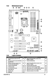
... (64bit, 240-pin module) DDR3 DIMM_B2 (64bit, 240-pin module) DRAM_LED 30.5cm (12.0in) AUDIO AAFP RTL 8111E CHA_FAN1 Lithium Cell CMOS Power PCIEX1_1 P8P67 LX PCIEX16_1 SATA6G_1 SATA6G_2 10 Super I/O PCIEX1_2 ASM 1083 PCI1 ALC 887-VD2 COM1 PCIEX16_2 PCI2 PCI3 SPDIF_OUT Intel® P67 11 SB_PWR SATA3G_4 SATA3G_3 32Mb... connector (10-1 pin AAFP) 1-26 10. Turbo Key II LED (O2LED2) 1-34 13. DRAM LED 1-34 Page 1-29 1-34 1-30 1-24 1-31 1-32 1-28 1-27 ASUS P8P67 LX 1-8
... (64bit, 240-pin module) DDR3 DIMM_B2 (64bit, 240-pin module) DRAM_LED 30.5cm (12.0in) AUDIO AAFP RTL 8111E CHA_FAN1 Lithium Cell CMOS Power PCIEX1_1 P8P67 LX PCIEX16_1 SATA6G_1 SATA6G_2 10 Super I/O PCIEX1_2 ASM 1083 PCI1 ALC 887-VD2 COM1 PCIEX16_2 PCI2 PCI3 SPDIF_OUT Intel® P67 11 SB_PWR SATA3G_4 SATA3G_3 32Mb... connector (10-1 pin AAFP) 1-26 10. Turbo Key II LED (O2LED2) 1-34 13. DRAM LED 1-34 Page 1-29 1-34 1-30 1-24 1-31 1-32 1-28 1-27 ASUS P8P67 LX 1-8

User Manual
Page 21
... corner of the arrow until the load plate is on the socket and damaging the CPU! Load plate 4. Gold triangle mark Alignment keys CPU notches ASUS P8P67 LX 1-10 3.
... corner of the arrow until the load plate is on the socket and damaging the CPU! Load plate 4. Gold triangle mark Alignment keys CPU notches ASUS P8P67 LX 1-10 3.
User Manual
Page 23
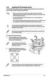
... and fan assembly comes in a push-pin design and requires no tool to install. • Use an LGA1155-compatible CPU heatsink and fan assembly only. ASUS P8P67 LX 1-12 If you buy a boxed Intel® processor, the package includes the CPU fan and heatsink assembly. Ensure that you install the CPU fan and...
... and fan assembly comes in a push-pin design and requires no tool to install. • Use an LGA1155-compatible CPU heatsink and fan assembly only. ASUS P8P67 LX 1-12 If you buy a boxed Intel® processor, the package includes the CPU fan and heatsink assembly. Ensure that you install the CPU fan and...

User Manual
Page 25
... with less power consumption. The figure illustrates the location of the DDR3 DIMM sockets: DIMM_A1 DIMM_A2 DIMM_B1 DIMM_B2 P8P67 LX Channel Channel A Channel B Sockets DIMM_A1 and DIMM_A2 DIMM_B1 and DIMM_B2 P8P67 LX 240-pin DDR3 DIMM sockets ASUS P8P67 LX 1-14 Rotate each fastener clockwise to prevent installation on a DDR2 DIMM socket. Carefully remove the heatsink and...
... with less power consumption. The figure illustrates the location of the DDR3 DIMM sockets: DIMM_A1 DIMM_A2 DIMM_B1 DIMM_B2 P8P67 LX Channel Channel A Channel B Sockets DIMM_A1 and DIMM_A2 DIMM_B1 and DIMM_B2 P8P67 LX 240-pin DDR3 DIMM sockets ASUS P8P67 LX 1-14 Rotate each fastener clockwise to prevent installation on a DDR2 DIMM socket. Carefully remove the heatsink and...

User Manual
Page 27
...Chip Brand - Timing Voltage OCZ OCZ3P18004GK 4GB(2 x 2GB) DS - - 8-8-8-27 1.9V DIMM socket support (Optional) A* B* C* • • • ASUS P8P67 LX 1-16 Size GEIL GU34GB2133C9DC(XMP) 4GB(2 x 2GB) KINGSTON KHX2133C9AD3T1K2/4GX(XMP) 4GB(2x 2GB) KINGSTON KHX2133C9AD3W1K2/4GX(XMP) 4GB(2x 2GB) SS/ Chip Chip DS... TX2000KLU-6GK(XMP) 6GB (3x 2GB) DS PATRIOT PVT36G2000LLK 6GB(3 x 2GB) DS Chip Brand Chip NO. P8P67 LX Motherboard Qualified Vendors Lists (QVL) DDR3-2133(O.C.) MHz capability Vendors Part No. Timing 9-9-9-28 - Size SS/DS Chip Brand Chip NO.
...Chip Brand - Timing Voltage OCZ OCZ3P18004GK 4GB(2 x 2GB) DS - - 8-8-8-27 1.9V DIMM socket support (Optional) A* B* C* • • • ASUS P8P67 LX 1-16 Size GEIL GU34GB2133C9DC(XMP) 4GB(2 x 2GB) KINGSTON KHX2133C9AD3T1K2/4GX(XMP) 4GB(2x 2GB) KINGSTON KHX2133C9AD3W1K2/4GX(XMP) 4GB(2x 2GB) SS/ Chip Chip DS... TX2000KLU-6GK(XMP) 6GB (3x 2GB) DS PATRIOT PVT36G2000LLK 6GB(3 x 2GB) DS Chip Brand Chip NO. P8P67 LX Motherboard Qualified Vendors Lists (QVL) DDR3-2133(O.C.) MHz capability Vendors Part No. Timing 9-9-9-28 - Size SS/DS Chip Brand Chip NO.

User Manual
Page 31
DDR3-1066 MHz capability Vendors Part No. ASUS P8P67 LX 1-20 Timing Voltage DIMM socket support (Optional) A* B* C* Crucial CT12864BA1067.8FF 1GB SS Micron 9GF22D9KPT 7 - • •• Crucial CT25664BA1067.16FF 2GB DS Micron 9HF22D9KPT 7 - • &#... both the blue slots and the black slots as two pairs of dual-channel memory configuration. Size SS/ DS Chip Brand Chip NO. Visit the ASUS website at www.asus.com for the latest QVL.
DDR3-1066 MHz capability Vendors Part No. ASUS P8P67 LX 1-20 Timing Voltage DIMM socket support (Optional) A* B* C* Crucial CT12864BA1067.8FF 1GB SS Micron 9GF22D9KPT 7 - • •• Crucial CT25664BA1067.16FF 2GB DS Micron 9HF22D9KPT 7 - • &#... both the blue slots and the black slots as two pairs of dual-channel memory configuration. Size SS/ DS Chip Brand Chip NO. Visit the ASUS website at www.asus.com for the latest QVL.
User Manual
Page 33
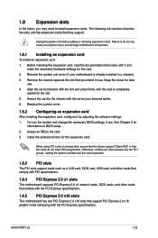
... on shared slots, ensure that the drivers support "Share IRQ" or that you removed earlier. 6. Unplug the power cord before adding or removing expansion cards. ASUS P8P67 LX 1-22 1.8 Expansion slots In the future, you may cause you physical injury and damage motherboard components. 1.8.1 Installing an expansion card To install an expansion card...
... on shared slots, ensure that the drivers support "Share IRQ" or that you removed earlier. 6. Unplug the power cord before adding or removing expansion cards. ASUS P8P67 LX 1-22 1.8 Expansion slots In the future, you may cause you physical injury and damage motherboard components. 1.8.1 Installing an expansion card To install an expansion card...

User Manual
Page 35
... to pins 1-2. 3. You can clear the CMOS memory of date, time, and system setup parameters by erasing the CMOS RTC RAM data. P8P67 LX CLRTC 12 23 Normal (Default) P8P67 LX Clear RTC RAM Clear RTC To erase the RTC RAM: 1. For system failure due to overclocking. Except when clearing the RTC RAM, never... BIOS setup to pins 2-3. 1.9 Jumpers 1. The onboard button cell battery powers the RAM data in CMOS. Plug the power cord and turn ON the computer. 4. ASUS P8P67 LX 1-24
... to pins 1-2. 3. You can clear the CMOS memory of date, time, and system setup parameters by erasing the CMOS RTC RAM data. P8P67 LX CLRTC 12 23 Normal (Default) P8P67 LX Clear RTC RAM Clear RTC To erase the RTC RAM: 1. For system failure due to overclocking. Except when clearing the RTC RAM, never... BIOS setup to pins 2-3. 1.9 Jumpers 1. The onboard button cell battery powers the RAM data in CMOS. Plug the power cord and turn ON the computer. 4. ASUS P8P67 LX 1-24
User Manual
Page 37
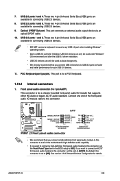
... Optical S/PDIF Out port. This port is set the item to USB 3.0 ports for faster and better performance for connecting USB 2.0 devices. 8. AAFP P8P67 LX SENSE2_RETUR SENSE1_RETUR PRESENCE# GND PORT2 L NC SENSE_SEND PORT2 R NC PORT1 R NC PORT1 L AGND PIN 1 Line out_L NC Line out_R MICPWR MIC2 PIN ...set the Front Panel Type item in the BIOS setup to [HD]. See section 2.5.6 Onboard Devices Configuration for connecting USB 2.0 devices. 9. ASUS P8P67 LX 1-26 These two 4-pin Universal Serial Bus (USB) ports are available for details. USB 2.0 ports 5 and 6. 7.
... Optical S/PDIF Out port. This port is set the item to USB 3.0 ports for faster and better performance for connecting USB 2.0 devices. 8. AAFP P8P67 LX SENSE2_RETUR SENSE1_RETUR PRESENCE# GND PORT2 L NC SENSE_SEND PORT2 R NC PORT1 R NC PORT1 L AGND PIN 1 Line out_L NC Line out_R MICPWR MIC2 PIN ...set the Front Panel Type item in the BIOS setup to [HD]. See section 2.5.6 Onboard Devices Configuration for connecting USB 2.0 devices. 9. ASUS P8P67 LX 1-26 These two 4-pin Universal Serial Bus (USB) ports are available for details. USB 2.0 ports 5 and 6. 7.
User Manual
Page 39
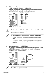
..., CHA_FAN1 and CHA_FAN2 connectors support the ASUS Fan Xpert feature. • If you install two VGA cards, we recommend that the black wire of each cable matches the ground pin of the system chassis. +5V SPDIFOUT GND P8P67 LX SPDIF_OUT P8P67 LX Digital audio connector The S/PDIF module is...connector, then install the module to the motherboard connector labeled CHA_FAN1 or CHA_FAN 2 for an additional Sony/Philips Digital Interface (S/PDIF) port. ASUS P8P67 LX 1-28 4. Do not place jumper caps on the motherboard, ensuring that you plug the rear chassis fan cable to a slot opening ...
..., CHA_FAN1 and CHA_FAN2 connectors support the ASUS Fan Xpert feature. • If you install two VGA cards, we recommend that the black wire of each cable matches the ground pin of the system chassis. +5V SPDIFOUT GND P8P67 LX SPDIF_OUT P8P67 LX Digital audio connector The S/PDIF module is...connector, then install the module to the motherboard connector labeled CHA_FAN1 or CHA_FAN 2 for an additional Sony/Philips Digital Interface (S/PDIF) port. ASUS P8P67 LX 1-28 4. Do not place jumper caps on the motherboard, ensuring that you plug the rear chassis fan cable to a slot opening ...
User Manual
Page 41
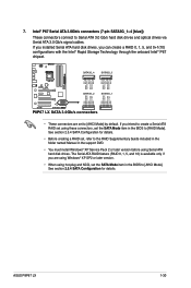
SATA3G_4 SATA3G_3 GND RSATA_TXP3 RSATA_TXN3 GND RSATA_RXP3 RSATA_RXN3 GND GND RSATA_TXP4 RSATA_TXN4 GND RSATA_RXP4 RSATA_RXN4 GND P8P67 LX SATA3G_2 SATA3G_1 GND RSATA_RXN1 RSATA_RXP1 GND RSATA_TXN1 RSATA_TXP1 GND GND RSATA_RXN2 RSATA_RXP2 GND RSATA_TXN2 RSATA_TXP2 GND P8P67 LX SATA 3.0Gb/s connectors • These connectors are using Windows® XP SP2 or later version. • When ... Technology through the onboard Intel® P67 chipset. 7. Intel® P67 Serial ATA 3.0Gb/s connectors (7-pin SATA3G_1~4 [blue]) These connectors connect to [RAID Mode]. ASUS P8P67 LX 1-30
SATA3G_4 SATA3G_3 GND RSATA_TXP3 RSATA_TXN3 GND RSATA_RXP3 RSATA_RXN3 GND GND RSATA_TXP4 RSATA_TXN4 GND RSATA_RXP4 RSATA_RXN4 GND P8P67 LX SATA3G_2 SATA3G_1 GND RSATA_RXN1 RSATA_RXP1 GND RSATA_TXN1 RSATA_TXP1 GND GND RSATA_RXN2 RSATA_RXP2 GND RSATA_TXN2 RSATA_TXP2 GND P8P67 LX SATA 3.0Gb/s connectors • These connectors are using Windows® XP SP2 or later version. • When ... Technology through the onboard Intel® P67 chipset. 7. Intel® P67 Serial ATA 3.0Gb/s connectors (7-pin SATA3G_1~4 [blue]) These connectors connect to [RAID Mode]. ASUS P8P67 LX 1-30
User Manual
Page 43
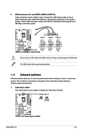
...USB_P8USB_P8+ GND NC USB+5V USB_P10USB_P10+ GND NC USB+5V USB_P12USB_P12+ GND NC P8P67 LX USB78 USB910 USB1112 USB+5V USB_P7USB_P7+ GND USB+5V USB_P9USB_P9+ GND USB+5V USB_P11USB_P11+ GND PIN 1 PIN 1 PIN 1 P8P67 LX USB2.0 connectors Never connect a 1394 cable to enhance system performance. 1. 9....11 Onboard switches Onboard switches allow you to fine-tune performance when working on a bare or open-case system. P8P67 LX P8P67 LX Turbo Key II switch ASUS P8P67 LX 1-32 The USB module cable is ideal for USB 2.0 ports. Turbo Key II switch This switch allows you to...
...USB_P8USB_P8+ GND NC USB+5V USB_P10USB_P10+ GND NC USB+5V USB_P12USB_P12+ GND NC P8P67 LX USB78 USB910 USB1112 USB+5V USB_P7USB_P7+ GND USB+5V USB_P9USB_P9+ GND USB+5V USB_P11USB_P11+ GND PIN 1 PIN 1 PIN 1 P8P67 LX USB2.0 connectors Never connect a 1394 cable to enhance system performance. 1. 9....11 Onboard switches Onboard switches allow you to fine-tune performance when working on a bare or open-case system. P8P67 LX P8P67 LX Turbo Key II switch ASUS P8P67 LX 1-32 The USB module cable is ideal for USB 2.0 ports. Turbo Key II switch This switch allows you to...

User Manual
Page 45
... is a reminder that the system is turned to locate the root problem within a second. O2LED2 P8P67 LX P8P67 LX Turbo Key II LED ASUS P8P67 LX 1-34 The illustration below shows the location of the onboard LED. P8P67 LX DRAM LED P8P67 LX DRAM LED 3. P8P67 LX SB_PWR P8P67 LX Onboard LED ON OFF Standby Power Powered Off 2. This user-friendly design provides an intuitional...
... is a reminder that the system is turned to locate the root problem within a second. O2LED2 P8P67 LX P8P67 LX Turbo Key II LED ASUS P8P67 LX 1-34 The illustration below shows the location of the onboard LED. P8P67 LX DRAM LED P8P67 LX DRAM LED 3. P8P67 LX SB_PWR P8P67 LX Onboard LED ON OFF Standby Power Powered Off 2. This user-friendly design provides an intuitional...
User Manual
Page 49
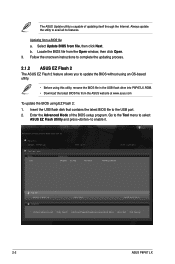
...14p 4194304 Exit DATE: 04/06/2011 P8P67LX.ROM File Info MODEL: P8P67 LX Help Info VER: 0303 DATE: 04/27/2011 [Enter] Select or Load [Tab] Switch [Up/Down/PageUp/PageDown/Home/End] Move [Esc] Exit [F2] Backup 2-2 ASUS P8P67 LX b. Locate the BIOS file from file, then click Next. Go ...to the Tool menu to select ASUS EZ Flash Utility and press to the USB port. 2. Enter the Advanced Mode of updating itself through...
...14p 4194304 Exit DATE: 04/06/2011 P8P67LX.ROM File Info MODEL: P8P67 LX Help Info VER: 0303 DATE: 04/27/2011 [Enter] Select or Load [Tab] Switch [Up/Down/PageUp/PageDown/Home/End] Move [Esc] Exit [F2] Backup 2-2 ASUS P8P67 LX b. Locate the BIOS file from file, then click Next. Go ...to the Tool menu to select ASUS EZ Flash Utility and press to the USB port. 2. Enter the Advanced Mode of updating itself through...
User Manual
Page 51
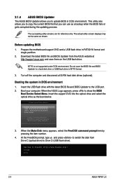
... not be same as the boot device. Insert the support DVD into the optical drive and select the optical drive as shown. C:\>d: D:\> 2-4 ASUS P8P67 LX This utility also allows you to copy the current BIOS file that you to update BIOS in NTFS format. 3. Download the latest BIOS file and...the BIOS Boot Device Select Menu. Before updating BIOS 1. At the FreeDOS prompt, type d: and press to switch the disk from the ASUS website at http://support.asus.com and save the BIOS file and BIOS Updater to Drive D (USB flash drive). Please select boot device: SATA: XXXXXXXXXXXXXXXX USB ...
... not be same as the boot device. Insert the support DVD into the optical drive and select the optical drive as shown. C:\>d: D:\> 2-4 ASUS P8P67 LX This utility also allows you to copy the current BIOS file that you to update BIOS in NTFS format. 3. Download the latest BIOS file and...the BIOS Boot Device Select Menu. Before updating BIOS 1. At the FreeDOS prompt, type d: and press to switch the disk from the ASUS website at http://support.asus.com and save the BIOS file and BIOS Updater to Drive D (USB flash drive). Please select boot device: SATA: XXXXXXXXXXXXXXXX USB ...
User Manual
Page 53
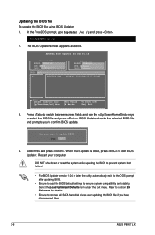
...press . The BIOS Updater screen appears as below. Are you to the DOS prompt after updating the BIOS file if you have disconnected them. 2-6 ASUS P8P67 LX Restart your computer. DO NOT shut down or reset the system while updating the BIOS to prevent system boot failure! • For BIOS Updater ... hard disk drives after updating BIOS. • Ensure to load the BIOS default settings to section 2.9 Exit menu for DOS V1.18 Current ROM BOARD: P8P67 LX VER: 0303 DATE: 04/27/2011 Update ROM BOARD: Unknown VER: Unknown DATE: Unknown PATH: A:\ A: P8P67LX.ROM 4194304 2011-04-27 17:30...
...press . The BIOS Updater screen appears as below. Are you to the DOS prompt after updating the BIOS file if you have disconnected them. 2-6 ASUS P8P67 LX Restart your computer. DO NOT shut down or reset the system while updating the BIOS to prevent system boot failure! • For BIOS Updater ... hard disk drives after updating BIOS. • Ensure to load the BIOS default settings to section 2.9 Exit menu for DOS V1.18 Current ROM BOARD: P8P67 LX VER: 0303 DATE: 04/27/2011 Update ROM BOARD: Unknown VER: Unknown DATE: Unknown PATH: A:\ A: P8P67LX.ROM 4194304 2011-04-27 17:30...


