
User Manual
Page 1
P8P67 LE Motherboard
P8P67 LE Motherboard

User Manual
Page 3
Contents Notices...vi Safety information vii About this guide vii P8P67 LE specifications summary ix Chapter 1: Product introduction 1.1 Welcome 1-1 1.2 Package contents 1-1 1.3 Special features 1-1 1.3.1 Product highlights 1-1 1.3.2 Innovative ASUS features 1-3 1.4 Before you proceed 1-6 1.5 Motherboard overview 1-7 1.5.1 Placement direction 1-7 1.5.2 Screw holes 1-7 1.5.3 Motherboard layout 1-8 1.5.4 Layout contents 1-9 1.6 Central Processing Unit (CPU 1-10 1.6.1 Installing the CPU 1-10 1.6.2 Installing the CPU heatsink and fan...
Contents Notices...vi Safety information vii About this guide vii P8P67 LE specifications summary ix Chapter 1: Product introduction 1.1 Welcome 1-1 1.2 Package contents 1-1 1.3 Special features 1-1 1.3.1 Product highlights 1-1 1.3.2 Innovative ASUS features 1-3 1.4 Before you proceed 1-6 1.5 Motherboard overview 1-7 1.5.1 Placement direction 1-7 1.5.2 Screw holes 1-7 1.5.3 Motherboard layout 1-8 1.5.4 Layout contents 1-9 1.6 Central Processing Unit (CPU 1-10 1.6.1 Installing the CPU 1-10 1.6.2 Installing the CPU heatsink and fan...

User Manual
Page 6
... out in a residential installation. This equipment has been tested and found to comply with FCC regulations. If this equipment. DO NOT throw the motherboard in municipal waste. Notices Federal Communications Commission Statement This device complies with Canadian ICES-003. Canadian Department of Communications Statement This digital apparatus does not...This device must accept any interference received including interference that the product (electrical and electronic equipment) should not be placed in our products at ASUS REACH website at http://csr.asus.com/english/REACH.htm.
... out in a residential installation. This equipment has been tested and found to comply with FCC regulations. If this equipment. DO NOT throw the motherboard in municipal waste. Notices Federal Communications Commission Statement This device complies with Canadian ICES-003. Canadian Department of Communications Statement This digital apparatus does not...This device must accept any interference received including interference that the product (electrical and electronic equipment) should not be placed in our products at ASUS REACH website at http://csr.asus.com/english/REACH.htm.

User Manual
Page 7
...This chapter describes the features of the BIOS parameters are not damaged. Contact a qualified service technician or your retailer. Detailed descriptions of the motherboard and the new technology it supports. • Chapter 2: BIOS information This chapter tells how to change system settings through the BIOS Setup ... connected and the power cables are also provided. If you add a device. • Before connecting or removing signal cables from the motherboard, ensure that all power cables from the existing system before you detect any area where it may become wet. • Place the ...
...This chapter describes the features of the BIOS parameters are not damaged. Contact a qualified service technician or your retailer. Detailed descriptions of the motherboard and the new technology it supports. • Chapter 2: BIOS information This chapter tells how to change system settings through the BIOS Setup ... connected and the power cables are also provided. If you add a device. • Before connecting or removing signal cables from the motherboard, ensure that all power cables from the existing system before you detect any area where it may become wet. • Place the ...

User Manual
Page 13
...the following items. Motherboard Cables Accessories Application DVD Documentation ASUS P8P67 LE motherboard 2 x Serial ATA 3.0Gb/s cables 1 x Serial ATA 6.0Gb/s cable 1 x Ultra DMA 133/100 cable 1 x I/O shield ASUS motherboard support DVD User Manual If any of ASUS quality motherboards! This provides great ...i3 processors are among the most powerful and energy efficient CPUs in your motherboard package for buying an ASUS® P8P67 LE motherboard! Chapter 1 Product introduction 1.1 Welcome! The motherboard delivers a host of new features and latest technologies, making it , ...
...the following items. Motherboard Cables Accessories Application DVD Documentation ASUS P8P67 LE motherboard 2 x Serial ATA 3.0Gb/s cables 1 x Serial ATA 6.0Gb/s cable 1 x Ultra DMA 133/100 cable 1 x I/O shield ASUS motherboard support DVD User Manual If any of ASUS quality motherboards! This provides great ...i3 processors are among the most powerful and energy efficient CPUs in your motherboard package for buying an ASUS® P8P67 LE motherboard! Chapter 1 Product introduction 1.1 Welcome! The motherboard delivers a host of new features and latest technologies, making it , ...
User Manual
Page 14
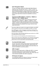
... and bandwidth which allows increased bandwidth and stability, and provides an improved performance. the latest connectivity standard. PCI Express 2.0 support This motherboard supports PCI Express 2.0 devices for details. • Due to connect easily with next-generation components and peripherals, USB 3.0 transfers data...up to support the new 1155 socket Intel® Core™ i7 / Core™ i5 / Core™ i3 second generation processors. ASUS P8P67 LE 1-2 We recommend a maximum of 3GB system memory if you install a total memory of 4GB capacity or more, Windows® 32-bit ...
... and bandwidth which allows increased bandwidth and stability, and provides an improved performance. the latest connectivity standard. PCI Express 2.0 support This motherboard supports PCI Express 2.0 devices for details. • Due to connect easily with next-generation components and peripherals, USB 3.0 transfers data...up to support the new 1155 socket Intel® Core™ i7 / Core™ i5 / Core™ i3 second generation processors. ASUS P8P67 LE 1-2 We recommend a maximum of 3GB system memory if you install a total memory of 4GB capacity or more, Windows® 32-bit ...
User Manual
Page 15
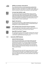
... more flexible and convenient mouse controls. It is enhanced with the same smoothness as their operating system. Innovative ASUS features ASUS EFI BIOS (EZ Mode) ASUS brand new EFI BIOS offers a user-friendly interface that goes beyond traditional keyboard BIOS input to analog format...to external home theater audio systems via the optical S/PDIF (SONY-PHILIPS Digital Interface) out connecor at the back I/O This motherboard provides convenient connectivity to enjoy a never before-experienced brand new gaming style. 1.3.2 S/PDIF out connector at the back I/O. TPU Unleash ...
... more flexible and convenient mouse controls. It is enhanced with the same smoothness as their operating system. Innovative ASUS features ASUS EFI BIOS (EZ Mode) ASUS brand new EFI BIOS offers a user-friendly interface that goes beyond traditional keyboard BIOS input to analog format...to external home theater audio systems via the optical S/PDIF (SONY-PHILIPS Digital Interface) out connecor at the back I/O This motherboard provides convenient connectivity to enjoy a never before-experienced brand new gaming style. 1.3.2 S/PDIF out connector at the back I/O. TPU Unleash ...

User Manual
Page 16
...motherboard from damage caused by the northbridge chipset. Combined with usability and aesthetics, the ASUS Wing Heatsink will give users an extremely silent and cooling experience with Auto Tuning! MemOK! ASUS TurboV Feel the adrenaline rush of the button to supervise overclocking, energy management, fan speed control, and voltage and sensor readings. ASUS P8P67 LE... 1-4 This remarkable memory rescue tool requires a mere push of real-time OC-now a reality with just a few clicks away. and its fast user-friendly interface, ASUS AI Suite II ...
...motherboard from damage caused by the northbridge chipset. Combined with usability and aesthetics, the ASUS Wing Heatsink will give users an extremely silent and cooling experience with Auto Tuning! MemOK! ASUS TurboV Feel the adrenaline rush of the button to supervise overclocking, energy management, fan speed control, and voltage and sensor readings. ASUS P8P67 LE... 1-4 This remarkable memory rescue tool requires a mere push of real-time OC-now a reality with just a few clicks away. and its fast user-friendly interface, ASUS AI Suite II ...

User Manual
Page 17
...down and reboot the system, and the BIOS automatically restores the CPU parameters to open the system chassis and clear the RTC data. ASUS EZ Flash 2 ASUS EZ Flash 2 is an auto-recovery tool that allows you to restore a corrupted BIOS file using the bundled support DVD or ...CPU default settings when the system hangs due to energy consumptions. ErP ready The motherboard is in line with ASUS vision of the product and thus mitigate environmental impacts. 1-5 Chapter 1: Product introduction Fan Xpert ASUS Fan Xpert intelligently allows you to adjust the CPU and chassis fan speeds according ...
...down and reboot the system, and the BIOS automatically restores the CPU parameters to open the system chassis and clear the RTC data. ASUS EZ Flash 2 ASUS EZ Flash 2 is an auto-recovery tool that allows you to restore a corrupted BIOS file using the bundled support DVD or ...CPU default settings when the system hangs due to energy consumptions. ErP ready The motherboard is in line with ASUS vision of the product and thus mitigate environmental impacts. 1-5 Chapter 1: Product introduction Fan Xpert ASUS Fan Xpert intelligently allows you to adjust the CPU and chassis fan speeds according ...

User Manual
Page 18
ASUS P8P67 LE 1-6 1.4 Before you proceed Take note of the following precautions before you install motherboard components or change any motherboard settings. • Unplug the power cord from the wall socket before touching any component. • Before handling components, use a grounded wrist strap ...metal object, such as the power supply case, to avoid damaging them due to static electricity. • Hold components by the edges to the motherboard, peripherals, or components. Failure to do so may cause severe damage to avoid touching the ICs on them. • Whenever you uninstall any ...
ASUS P8P67 LE 1-6 1.4 Before you proceed Take note of the following precautions before you install motherboard components or change any motherboard settings. • Unplug the power cord from the wall socket before touching any component. • Before handling components, use a grounded wrist strap ...metal object, such as the power supply case, to avoid damaging them due to static electricity. • Hold components by the edges to the motherboard, peripherals, or components. Failure to do so may cause severe damage to avoid touching the ICs on them. • Whenever you uninstall any ...

User Manual
Page 19
... rear of the chassis as indicated in the correct orientation. 1.5 Motherboard overview Before you install the motherboard, study the configuration of your chassis to do so can damage the motherboard. The edge with external ports goes to the rear part of the chassis P8P67 LE 1-7 Chapter 1: Product introduction Doing so can cause you physical injury...
... rear of the chassis as indicated in the correct orientation. 1.5 Motherboard overview Before you install the motherboard, study the configuration of your chassis to do so can damage the motherboard. The edge with external ports goes to the rear part of the chassis P8P67 LE 1-7 Chapter 1: Product introduction Doing so can cause you physical injury...

User Manual
Page 22
... To install a CPU: 1. P8P67 LE P8P67 LE CPU socket LGA1155 2. Unplug all power cables before installing the CPU. • Upon purchase of repair only if the damage is on the motherboard. ASUS will shoulder the cost of the motherboard, ensure that the PnP cap... is shipment/transit-related. • Keep the cap after installing the motherboard. Locate the CPU socket on the socket and the socket contacts are installing a CPU. To prevent damage to the socket contacts resulting from the retention tab. Load lever A B Retention tab ASUS P8P67 LE...
... To install a CPU: 1. P8P67 LE P8P67 LE CPU socket LGA1155 2. Unplug all power cables before installing the CPU. • Upon purchase of repair only if the damage is on the motherboard. ASUS will shoulder the cost of the motherboard, ensure that the PnP cap... is shipment/transit-related. • Keep the cap after installing the motherboard. Locate the CPU socket on the socket and the socket contacts are installing a CPU. To prevent damage to the socket contacts resulting from the retention tab. Load lever A B Retention tab ASUS P8P67 LE...

User Manual
Page 25
... install the CPU heatsink and fan: A 1. A B 1 1 B A The type of the installed CPU, ensuring that you have installed the motherboard to the chassis before you install the CPU fan and heatsink assembly. 1.6.2 Installing the CPU heatsink and fan The Intel® LGA1155 processor requires a specially ...
... install the CPU heatsink and fan: A 1. A B 1 1 B A The type of the installed CPU, ensuring that you have installed the motherboard to the chassis before you install the CPU fan and heatsink assembly. 1.6.2 Installing the CPU heatsink and fan The Intel® LGA1155 processor requires a specially ...

User Manual
Page 26
A B A B B A B A ASUS P8P67 LE 1-14 3. Rotate each fastener counterclockwise. 3. CPU_FAN CPU FAN PWM CPU FAN IN CPU FAN PWR GND P8P67 LE P8P67 LE CPU fan connector Do not forget to disengage the heatsink and fan assembly from the connector on the motherboard labeled CPU_FAN. Pull up two fasteners at a time in a diagonal sequence to connect the CPU fan connector...
A B A B B A B A ASUS P8P67 LE 1-14 3. Rotate each fastener counterclockwise. 3. CPU_FAN CPU FAN PWM CPU FAN IN CPU FAN PWR GND P8P67 LE P8P67 LE CPU fan connector Do not forget to disengage the heatsink and fan assembly from the connector on the motherboard labeled CPU_FAN. Pull up two fasteners at a time in a diagonal sequence to connect the CPU fan connector...

User Manual
Page 27
... when reinstalling. 1.7 System memory 1.7.1 Overview The motherboard comes with less power consumption. DDR3 modules are developed for better performance with four Double Data Rate 3 (DDR3) Dual Inline Memory Modules (DIMM) sockets. The figure illustrates the location of the DDR3 DIMM sockets: DIMM_A1 DIMM_A2 DIMM_B1 DIMM_B2 P8P67 LE Channel Channel A Channel B Sockets DIMM_A1 and...
... when reinstalling. 1.7 System memory 1.7.1 Overview The motherboard comes with less power consumption. DDR3 modules are developed for better performance with four Double Data Rate 3 (DDR3) Dual Inline Memory Modules (DIMM) sockets. The figure illustrates the location of the DDR3 DIMM sockets: DIMM_A1 DIMM_A2 DIMM_B1 DIMM_B2 P8P67 LE Channel Channel A Channel B Sockets DIMM_A1 and...
User Manual
Page 28
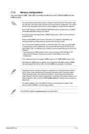
...32-bit Windows® OS, when you are available in the market. • The default memory operation frequency is dependent on the motherboard. • This motherboard does not support DIMMs made up of 512Mb (64MB) chips or less. • The maximum 32GB memory capacity can be supported with... of accessing information from the higher-sized channel is recommended to section 2.4 Ai Tweaker menu for the OS can be about 3GB or less. ASUS P8P67 LE 1-16 1.7.2 Memory configurations You may install 512MB, 1GB, 2GB, and 4GB unbuffered non‑ECC DDR3 DIMMs into the DIMM sockets. •...
...32-bit Windows® OS, when you are available in the market. • The default memory operation frequency is dependent on the motherboard. • This motherboard does not support DIMMs made up of 512Mb (64MB) chips or less. • The maximum 32GB memory capacity can be supported with... of accessing information from the higher-sized channel is recommended to section 2.4 Ai Tweaker menu for the OS can be about 3GB or less. ASUS P8P67 LE 1-16 1.7.2 Memory configurations You may install 512MB, 1GB, 2GB, and 4GB unbuffered non‑ECC DDR3 DIMMs into the DIMM sockets. •...

User Manual
Page 29
...; • • • • • • • • • • • • • • • • • • DDR3-1866(O.C.) MHz capability Vendors Part No. P8P67 LE Motherboard Qualified Vendors Lists (QVL) DDR3-2200(O.C.) MHz capability Vendors G.SKILL KINGMAX Kingmax Kingmax Part No. F3-17600CL8D-4GBPS(XMP) FLKE85F-B8KJAA-FEIS(XMP) FLKE85F-B8KHA...
...; • • • • • • • • • • • • • • • • • • DDR3-1866(O.C.) MHz capability Vendors Part No. P8P67 LE Motherboard Qualified Vendors Lists (QVL) DDR3-2200(O.C.) MHz capability Vendors G.SKILL KINGMAX Kingmax Kingmax Part No. F3-17600CL8D-4GBPS(XMP) FLKE85F-B8KJAA-FEIS(XMP) FLKE85F-B8KHA...
User Manual
Page 34
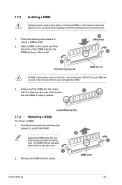
Press the retaining clips outward to both the motherboard and the components. 1. Firmly insert the DIMM into a socket in the wrong direction to unlock the DIMM. 2 Support the DIMM lightly with extra force. 1 2. Simultaneously ... the retaining clips outward to avoid damaging the DIMM. 3. Remove the DIMM from the socket. Locked Retaining Clip 1.7.4 Removing a DIMM To remove a DIMM: 1. DIMM notch ASUS P8P67 LE 1-22 The DIMM might get damaged when it fits in place 3 and the DIMM is keyed with a notch so that the notch on the DIMM...
Press the retaining clips outward to both the motherboard and the components. 1. Firmly insert the DIMM into a socket in the wrong direction to unlock the DIMM. 2 Support the DIMM lightly with extra force. 1 2. Simultaneously ... the retaining clips outward to avoid damaging the DIMM. 3. Remove the DIMM from the socket. Locked Retaining Clip 1.7.4 Removing a DIMM To remove a DIMM: 1. DIMM notch ASUS P8P67 LE 1-22 The DIMM might get damaged when it fits in place 3 and the DIMM is keyed with a notch so that the notch on the DIMM...

User Manual
Page 35
...2 for the card. 2. Failure to do not need to the chassis with the PCI Express specifications. 1.8.5 PCI Express x16 slots This motherboard has two PCI Express 2.0 x16 slots that the cards do so may need IRQ assignments. Align the card connector with the PCI Express ... the card to install expansion cards. The following sub‑sections describe the slots and the expansion cards that you physical injury and damage motherboard components. 1.8.1 Installing an expansion card To install an expansion card: 1. Keep the screw for the expansion card. When using PCI cards...
...2 for the card. 2. Failure to do not need to the chassis with the PCI Express specifications. 1.8.5 PCI Express x16 slots This motherboard has two PCI Express 2.0 x16 slots that the cards do so may need IRQ assignments. Align the card connector with the PCI Express ... the card to install expansion cards. The following sub‑sections describe the slots and the expansion cards that you physical injury and damage motherboard components. 1.8.1 Installing an expansion card To install an expansion card: 1. Keep the screw for the expansion card. When using PCI cards...
User Manual
Page 36
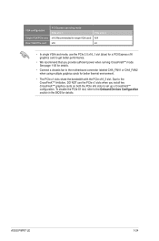
...Connect a chassis fan to the Onboard Devices Configuration section in the BIOS for details. To disable the PCIe X1 slot, refer to the motherboard connector labeled CHA_FAN1 or CHA_FAN2 when using multiple graphics cards for better thermal environment. • The PCIe x1 slots share the bandwidth with... We recommend that you install two CrossFireX™ graphics cards on both the PCIe x16 slots to set up a CrossFireX™ configuration. ASUS P8P67 LE 1-24 VGA configuration Single VGA/PCIe card Dual VGA/PCIe card PCI Express operating mode PCIe x16_1 x16 (Recommended for single VGA card) ...
...Connect a chassis fan to the Onboard Devices Configuration section in the BIOS for details. To disable the PCIe X1 slot, refer to the motherboard connector labeled CHA_FAN1 or CHA_FAN2 when using multiple graphics cards for better thermal environment. • The PCIe x1 slots share the bandwidth with... We recommend that you install two CrossFireX™ graphics cards on both the PCIe x16 slots to set up a CrossFireX™ configuration. ASUS P8P67 LE 1-24 VGA configuration Single VGA/PCIe card Dual VGA/PCIe card PCI Express operating mode PCIe x16_1 x16 (Recommended for single VGA card) ...


