
User Manual
Page 3
...this guide...viii P8P67 EVO specifications summary x Chapter 1: Product introduction 1.1 Welcome!...1-1 1.2 Package contents 1-1 1.3 Special features 1-2 1.3.1 Product highlights 1-2 1.3.2 Dual Intelligent Processors 2 with DIGI+ VRM 1-3 1.3.3 ASUS Exclusive Features 1-3 1.3.4 ASUS Quiet Thermal Solution 1-4 1.3.5 ASUS EZ DIY 1-4... CPU heatsink and fan assembly installation 2-33 2.3.4 DIMM installation 2-35 2.3.5 Motherboard installation 2-36 2.3.6 ATX Power connection 2-38 2.3.7 SATA device connection 2-39 2.3.8 Front I/O Connector 2-40 2.3.9 Expension Card ...
...this guide...viii P8P67 EVO specifications summary x Chapter 1: Product introduction 1.1 Welcome!...1-1 1.2 Package contents 1-1 1.3 Special features 1-2 1.3.1 Product highlights 1-2 1.3.2 Dual Intelligent Processors 2 with DIGI+ VRM 1-3 1.3.3 ASUS Exclusive Features 1-3 1.3.4 ASUS Quiet Thermal Solution 1-4 1.3.5 ASUS EZ DIY 1-4... CPU heatsink and fan assembly installation 2-33 2.3.4 DIMM installation 2-35 2.3.5 Motherboard installation 2-36 2.3.6 ATX Power connection 2-38 2.3.7 SATA device connection 2-39 2.3.8 Front I/O Connector 2-40 2.3.9 Expension Card ...
User Manual
Page 12
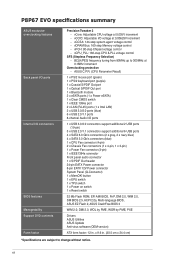
ASUS C.P.R. (CPU Parameter Recall) 1 x PS/2 mouse port (green) 1 x PS/2 keyboard port (purple) 1 x Coaxial S/PDIF Out port 1 x Optical S/PDIF Out port 1 x Bluetooth module 2 x eSATA ports (1 x Power eSATA)...by PME, WOR by PME, PXE Drivers ASUS Utilities ASUS Update Anti-virus software (OEM version) ATX form factor: 12 in . (30.5 cm x 24.4 cm) *Specifications are subject to 300MHz at 0.1MHz increment Overclocking protection - xii vPCH: 90-step Chipset voltage control - x 9.6 in . P8P67 EVO specifications summary ASUS exclusive overclocking features Back panel I/O ports Internal...
ASUS C.P.R. (CPU Parameter Recall) 1 x PS/2 mouse port (green) 1 x PS/2 keyboard port (purple) 1 x Coaxial S/PDIF Out port 1 x Optical S/PDIF Out port 1 x Bluetooth module 2 x eSATA ports (1 x Power eSATA)...by PME, WOR by PME, PXE Drivers ASUS Utilities ASUS Update Anti-virus software (OEM version) ATX form factor: 12 in . (30.5 cm x 24.4 cm) *Specifications are subject to 300MHz at 0.1MHz increment Overclocking protection - xii vPCH: 90-step Chipset voltage control - x 9.6 in . P8P67 EVO specifications summary ASUS exclusive overclocking features Back panel I/O ports Internal...

User Manual
Page 19
ASUS P8P67 EVO 2-1 Chapter 2: Chapter 2 Hardware information 2.1 Before you proceed Take note of the following precautions before you install motherboard components or change any motherboard settings. • Unplug ... it on a grounded antistatic pad or in the bag that came with the component. • Before you install or remove any component, ensure that the ATX power supply is switched off or the power cord is detached from the power supply.
ASUS P8P67 EVO 2-1 Chapter 2: Chapter 2 Hardware information 2.1 Before you proceed Take note of the following precautions before you install motherboard components or change any motherboard settings. • Unplug ... it on a grounded antistatic pad or in the bag that came with the component. • Before you install or remove any component, ensure that the ATX power supply is switched off or the power cord is detached from the power supply.

User Manual
Page 45
Find the proper orientation and push down firmly until the connectors completely fit. ASUS P8P67 EVO 2-27 if you connect a high-definition front panel audio module to this connector. • We recommend that supports either HD Audio or legacy...of the motherboard's high-definition audio capability. The power supply plugs are for a chassis-mounted front panel audio I /O module cable to this connector to [AC97]. ATX power connectors (24-pin EATXPWR; 8-pin EATX12V) These connectors are designed to [HD]; By default, this connector, set to [HD]. 10. Chapter 2 9. ...
Find the proper orientation and push down firmly until the connectors completely fit. ASUS P8P67 EVO 2-27 if you connect a high-definition front panel audio module to this connector. • We recommend that supports either HD Audio or legacy...of the motherboard's high-definition audio capability. The power supply plugs are for a chassis-mounted front panel audio I /O module cable to this connector to [AC97]. ATX power connectors (24-pin EATXPWR; 8-pin EATX12V) These connectors are designed to [HD]; By default, this connector, set to [HD]. 10. Chapter 2 9. ...

User Manual
Page 46
... • Use of 350 W. • Do not forget to the Recommended Power Supply Wattage Calculator at http://support.asus. Chapter 2 • For a fully configured system, we recommend that complies with ATX 12 V Specification 2.0 (or later version) and provides a minimum power of a PSU with a higher power output ...plug; PSU Suggested List AcBel PC7030 AcBel API5PC36 AcBel PC6018 AMA AA1200U-C AMA AA1000U-C Antec SG-850 Antec EA-380 ASUS P-50GA ASUS P-55GA ASUS U-65GA ASUS U-75HA Be quiet BN073 Be quiet BN077 Be quiet P6-PRO-850W Bubalus PE600WJD CoolerMaster RS-650 CoolerMaster RS-750 ...
... • Use of 350 W. • Do not forget to the Recommended Power Supply Wattage Calculator at http://support.asus. Chapter 2 • For a fully configured system, we recommend that complies with ATX 12 V Specification 2.0 (or later version) and provides a minimum power of a PSU with a higher power output ...plug; PSU Suggested List AcBel PC7030 AcBel API5PC36 AcBel PC6018 AMA AA1200U-C AMA AA1000U-C Antec SG-850 Antec EA-380 ASUS P-50GA ASUS P-55GA ASUS U-65GA ASUS U-75HA Be quiet BN073 Be quiet BN077 Be quiet P6-PRO-850W Bubalus PE600WJD CoolerMaster RS-650 CoolerMaster RS-750 ...

User Manual
Page 47
System panel connector (20-8 pin PANEL) This connector supports several chassis-mounted functions. ASUS P8P67 EVO 2-29 Chapter 2 • System power LED (2-pin PLED) This 2-pin connector is for the chassis-mounted reset button for system reboot without turning off the ... this connector. The speaker allows you turn on the BIOS settings. 11. Connect the chassis power LED cable to hear system beeps and warnings. • ATX power button/soft-off mode depending on the system power, and blinks when the system is for the chassis-mounted system warning speaker.
System panel connector (20-8 pin PANEL) This connector supports several chassis-mounted functions. ASUS P8P67 EVO 2-29 Chapter 2 • System power LED (2-pin PLED) This 2-pin connector is for the chassis-mounted reset button for system reboot without turning off the ... this connector. The speaker allows you turn on the BIOS settings. 11. Connect the chassis power LED cable to hear system beeps and warnings. • ATX power button/soft-off mode depending on the system power, and blinks when the system is for the chassis-mounted system warning speaker.

User Manual
Page 56
2.3.6 1 ATX Power connection 2 OR OR Chapter 2 2-38 Chapter 2: Hardware information
2.3.6 1 ATX Power connection 2 OR OR Chapter 2 2-38 Chapter 2: Hardware information

User Manual
Page 64
...is ON, pressing the power switch for the first time 1. Connect the power cord to section 3.5.7 APM for assistance. External SCSI devices (starting with ATX power supplies, the system LED lights up when you turned on test. System power 6. While the tests are off mode regardless of the system chassis...standby" feature, the monitor LED may have failed a power-on the power, the system may light up or change from the time you press the ATX power button. Monitor b. If you do not see anything within 30 seconds from orange to enter the BIOS Setup. Chapter 2 2.4 Starting up for less...
...is ON, pressing the power switch for the first time 1. Connect the power cord to section 3.5.7 APM for assistance. External SCSI devices (starting with ATX power supplies, the system LED lights up when you turned on test. System power 6. While the tests are off mode regardless of the system chassis...standby" feature, the monitor LED may have failed a power-on the power, the system may light up or change from the time you press the ATX power button. Monitor b. If you do not see anything within 30 seconds from orange to enter the BIOS Setup. Chapter 2 2.4 Starting up for less...

User Manual
Page 86
...On By RTC [Disabled] [Disabled] Disables RTC to generate a wake event. [Enabled] When set values. 3-22 Chapter 3: BIOS setup Chapter 3 This feature requires an ATX power supply that provides at least 1A on the +5VSB lead. Power On By PCIE [Disabled] [Disabled] Disables the PCIE devices to generate a wake event... on state after an AC power loss. [Power Off] The system goes into off or on the +5VSB lead. This feature requires an ATX power supply that provides at least 1A on state, whatever the system state was before the AC power loss. Advanced Mode Exit Main Back Ai...
...On By RTC [Disabled] [Disabled] Disables RTC to generate a wake event. [Enabled] When set values. 3-22 Chapter 3: BIOS setup Chapter 3 This feature requires an ATX power supply that provides at least 1A on the +5VSB lead. Power On By PCIE [Disabled] [Disabled] Disables the PCIE devices to generate a wake event... on state after an AC power loss. [Power Off] The system goes into off or on the +5VSB lead. This feature requires an ATX power supply that provides at least 1A on state, whatever the system state was before the AC power loss. Advanced Mode Exit Main Back Ai...

