
P8H61-M2/TPM/SI R2.0 User's Manual
Page 3
...About this guide vi P8H61-M2/TPM/SI R2.0 specifications summary viii Chapter 1: Product introduction 1.1 Welcome 1-1 1.2 Package contents 1-1 1.3 Special features 1-1 1.3.1 Product highlights 1-1 1.3.2 Innovative ASUS features 1-3 1.4 Before you proceed 1-5 1.5 Motherboard overview 1-6 1.5.1 Placement direction 1-6 1.5.2 Screw holes 1-6 1.5.3 Motherboard layout 1-7 1.5.4 Layout contents 1-7 1.6 Central Processing Unit (CPU 1-8 1.6.1 ... Connectors 1-21 1.10.1 Rear panel ports 1-21 1.10.2 Internal connectors 1-22 iii E7361_P8H61-M2-TPM-SI R2.0_Manua3 3 5/16/12 1:43:40 PM
...About this guide vi P8H61-M2/TPM/SI R2.0 specifications summary viii Chapter 1: Product introduction 1.1 Welcome 1-1 1.2 Package contents 1-1 1.3 Special features 1-1 1.3.1 Product highlights 1-1 1.3.2 Innovative ASUS features 1-3 1.4 Before you proceed 1-5 1.5 Motherboard overview 1-6 1.5.1 Placement direction 1-6 1.5.2 Screw holes 1-6 1.5.3 Motherboard layout 1-7 1.5.4 Layout contents 1-7 1.6 Central Processing Unit (CPU 1-8 1.6.1 ... Connectors 1-21 1.10.1 Rear panel ports 1-21 1.10.2 Internal connectors 1-22 iii E7361_P8H61-M2-TPM-SI R2.0_Manua3 3 5/16/12 1:43:40 PM
P8H61-M2/TPM/SI R2.0 User's Manual
Page 18
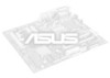
1.6 Central Processing Unit (CPU) The motherboard comes with your retailer immediately if the PnP cap is released from incorrect CPU installation/removal, or misplacement/loss/incorrect removal of the PnP cap. 1.6.1 Installing the CPU To install a CPU: 1. ASUS will process Return Merchandise Authorization ... does not cover damage to the socket contacts resulting from the retention tab. Load lever A B Retention tab 1-8 E7361_P8H61-M2-TPM-SI R2.0_Manua8 8 ASUS P8H61-M2/TPM/SI R2.0 5/16/12 1:43:59 PM Unplug all power cables before installing the CPU. • Upon purchase of repair...
1.6 Central Processing Unit (CPU) The motherboard comes with your retailer immediately if the PnP cap is released from incorrect CPU installation/removal, or misplacement/loss/incorrect removal of the PnP cap. 1.6.1 Installing the CPU To install a CPU: 1. ASUS will process Return Merchandise Authorization ... does not cover damage to the socket contacts resulting from the retention tab. Load lever A B Retention tab 1-8 E7361_P8H61-M2-TPM-SI R2.0_Manua8 8 ASUS P8H61-M2/TPM/SI R2.0 5/16/12 1:43:59 PM Unplug all power cables before installing the CPU. • Upon purchase of repair...

P8H61-M2/TPM/SI R2.0 User's Manual
Page 29
... the bracket opposite the slot that came with the PCI Express specifications. See Chapter 2 for the card. 2. Failure to install expansion cards. Remove the system unit cover (if your motherboard is completely seated on shared slots, ensure that the drivers support "Share IRQ" or that they support. Keep the screw for.... 2. Assign an IRQ to the chassis with the slot and press firmly until the card is already installed in a chassis). 3. Chapter 1: Product introduction 1-19 E7361_P8H61-M2-TPM-SI R2.0_Manua19 19 5/16/12 1:44:19 PM
... the bracket opposite the slot that came with the PCI Express specifications. See Chapter 2 for the card. 2. Failure to install expansion cards. Remove the system unit cover (if your motherboard is completely seated on shared slots, ensure that the drivers support "Share IRQ" or that they support. Keep the screw for.... 2. Assign an IRQ to the chassis with the slot and press firmly until the card is already installed in a chassis). 3. Chapter 1: Product introduction 1-19 E7361_P8H61-M2-TPM-SI R2.0_Manua19 19 5/16/12 1:44:19 PM

P8H61-M2/TPM/SI R2.0 User's Manual
Page 32
...power supply unit (PSU) that complies with more power-consuming devices or when you intend to install additional devices. USB 2.0 ports 3 and 4. These two 4-pin Universal Serial Bus (USB) ports are available for details. 1-22 E7361_P8H61-M2-TPM-SI R2.0_Manua22 22 ASUS P8H61-M2/TPM/SI R2.0 ... Volts GND +3 Volts +3 Volts PIN 1 GND +5 Volts +5 Volts +5 Volts -5 Volts GND GND GND PSON# GND -12 Volts +3 Volts P8H61-M2/TPM/SI R2.0 ATX power connectors • For a fully configured system, we recommend that you are designed to USB 2.0/1.1 devices. 1.10.2 Internal connectors 1....
...power supply unit (PSU) that complies with more power-consuming devices or when you intend to install additional devices. USB 2.0 ports 3 and 4. These two 4-pin Universal Serial Bus (USB) ports are available for details. 1-22 E7361_P8H61-M2-TPM-SI R2.0_Manua22 22 ASUS P8H61-M2/TPM/SI R2.0 ... Volts GND +3 Volts +3 Volts PIN 1 GND +5 Volts +5 Volts +5 Volts -5 Volts GND GND GND PSON# GND -12 Volts +3 Volts P8H61-M2/TPM/SI R2.0 ATX power connectors • For a fully configured system, we recommend that you are designed to USB 2.0/1.1 devices. 1.10.2 Internal connectors 1....
P8H61-M2/TPM/SI R2.0 User's Manual
Page 67
Operation is subject to the following two conditions: (1) this device may not cause interference, and (2) this unit not expressly approved by one or more of the FCC Rules. These limits are designed to this device must accept any interference, including ...du Règlement sur le matériel brouilleur du Canada. However, there is no guarantee that to comply with FCC regulations. Appendices A-1 E7361_P8H61-M2-TPM-SI R2.0_Manua1 1 5/16/12 1:45:11 PM IC: Canadian Compliance Statement Complies with RSS 210 of the Canadian interference-causing equipment regulations. This device...
Operation is subject to the following two conditions: (1) this device may not cause interference, and (2) this unit not expressly approved by one or more of the FCC Rules. These limits are designed to this device must accept any interference, including ...du Règlement sur le matériel brouilleur du Canada. However, there is no guarantee that to comply with FCC regulations. Appendices A-1 E7361_P8H61-M2-TPM-SI R2.0_Manua1 1 5/16/12 1:45:11 PM IC: Canadian Compliance Statement Complies with RSS 210 of the Canadian interference-causing equipment regulations. This device...


