
User Manual
Page 14
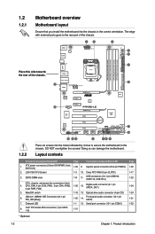
... 4. MemOK! ATX power connectors (24-pin EATXPWR, 8-pin EATX12V) 1-20 9. DDR3 DIMM slots 1-8 11. DO NOT overtighten the screws! LGA1156 CPU Socket 1-3 10. Clear RTC RAM (3-pin CLRTC) 1-17 3. JMicron® JMB361 IDE Connector (40-1 pin PRI_IDE [Blue]) 1-25 14. Optical drive audio connector (4-pin CD) 1-24 6. Onboard LED 1-1 15. 1.2 1.2.1 Motherboard...
... 4. MemOK! ATX power connectors (24-pin EATXPWR, 8-pin EATX12V) 1-20 9. DDR3 DIMM slots 1-8 11. DO NOT overtighten the screws! LGA1156 CPU Socket 1-3 10. Clear RTC RAM (3-pin CLRTC) 1-17 3. JMicron® JMB361 IDE Connector (40-1 pin PRI_IDE [Blue]) 1-25 14. Optical drive audio connector (4-pin CD) 1-24 6. Onboard LED 1-1 15. 1.2 1.2.1 Motherboard...
User Manual
Page 29
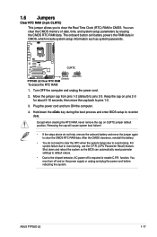
... CMOS memory of date, time, and system setup parameters by erasing the CMOS RTC RAM data. You must turn ON the computer. 4. Move the jumper cap from pins 1-2 (default)... to re-enter data. Except when clearing the RTC RAM, never remove the cap on the power supply or unplug and plug the power cord before...RAM data. Plug the power cord and turn off is required to overclocking. function. Removing the cap will cause system boot failure! • If the steps above do not need to clear the RTC when the system hangs due to enable C.P.R. ASUS P7P55D LE...
... CMOS memory of date, time, and system setup parameters by erasing the CMOS RTC RAM data. You must turn ON the computer. 4. Move the jumper cap from pins 1-2 (default)... to re-enter data. Except when clearing the RTC RAM, never remove the cap on the power supply or unplug and plug the power cord before...RAM data. Plug the power cord and turn off is required to overclocking. function. Removing the cap will cause system boot failure! • If the steps above do not need to clear the RTC when the system hangs due to enable C.P.R. ASUS P7P55D LE...
User Manual
Page 59
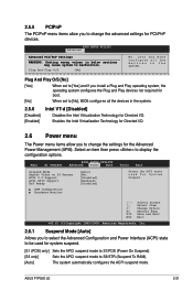
Select an item then press to malfunction. ASUS P7P55D LE 2-21 BIOS SETUP UTILITY Advanced Advanced PCI/PnP Settings WARNING: Setting wrong values in below sections may cause system to display the configuration options. Plug ... and Play operating system, the operating system configures the Plug and Play devices not required for boot. [No] When set to S3/STR (Suspend To RAM). [Auto] The system automatically configures the ACPI suspend mode. Change Option F1 General Help F10 Save and Exit ESC Exit v02.61 (C)Copyright 1985-2009...
Select an item then press to malfunction. ASUS P7P55D LE 2-21 BIOS SETUP UTILITY Advanced Advanced PCI/PnP Settings WARNING: Setting wrong values in below sections may cause system to display the configuration options. Plug ... and Play operating system, the operating system configures the Plug and Play devices not required for boot. [No] When set to S3/STR (Suspend To RAM). [Auto] The system automatically configures the ACPI suspend mode. Change Option F1 General Help F10 Save and Exit ESC Exit v02.61 (C)Copyright 1985-2009...
User Manual
Page 65
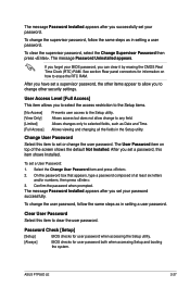
... on top of at least six letters and/or numbers, then press . 3. ASUS P7P55D LE 2-27 The message Password Installed appears after you can clear it by erasing the CMOS Real Time Clock (RTC) RAM. Clear User Password Select this item shows Installed. See section Rear panel connectors for... the user password, follow the same steps as in setting a user password. To change the user password. After you to erase the RTC RAM. To clear the supervisor password, select the Change Supervisor Password then press . To change other items appear to allow change to any field....
... on top of at least six letters and/or numbers, then press . 3. ASUS P7P55D LE 2-27 The message Password Installed appears after you can clear it by erasing the CMOS Real Time Clock (RTC) RAM. Clear User Password Select this item shows Installed. See section Rear panel connectors for... the user password, follow the same steps as in setting a user password. To change the user password. After you to erase the RTC RAM. To clear the supervisor password, select the Change Supervisor Password then press . To change other items appear to allow change to any field....
User Manual
Page 68
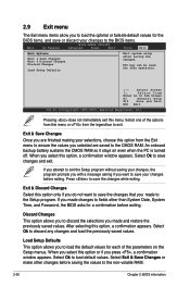
...8592;→ Select Screen ↑↓ Select Item Enter Go to the CMOS RAM. If you made changes to fields other changes before exiting. Discard Changes This option allows you to the non...-volatile RAM. 2-30 Chapter 2: BIOS information Select Ok to save the changes that you press , a...one of the parameters on even when the PC is turned off. An onboard backup battery sustains the CMOS RAM so it stays on the Setup menus. Select Exit & Save Changes or make other than System Date,...
...8592;→ Select Screen ↑↓ Select Item Enter Go to the CMOS RAM. If you made changes to fields other changes before exiting. Discard Changes This option allows you to the non...-volatile RAM. 2-30 Chapter 2: BIOS information Select Ok to save the changes that you press , a...one of the parameters on even when the PC is turned off. An onboard backup battery sustains the CMOS RAM so it stays on the Setup menus. Select Exit & Save Changes or make other than System Date,...


