
User Manual
Page 2
...repaired, modified or altered, unless such repair, modification of their respective companies, and are included in writing by downloading it from http://support.asus.com/download; Legal Compliance Dept. 15 Li Te Rd., Beitou, Taipei 112 Taiwan In your contact details so that uses the Library")...THE PRODUCTS AND SOFTWARE DESCRIBED IN IT. Copies of these licenses are used only for the cost of ASUSTeK Computer Inc. ("ASUS"). IN NO EVENT SHALL ASUS, ITS DIRECTORS, OFFICERS, EMPLOYEES OR AGENTS BE LIABLE FOR ANY INDIRECT, SPECIAL, INCIDENTAL, OR CONSEQUENTIAL DAMAGES (INCLUDING DAMAGES FOR...
...repaired, modified or altered, unless such repair, modification of their respective companies, and are included in writing by downloading it from http://support.asus.com/download; Legal Compliance Dept. 15 Li Te Rd., Beitou, Taipei 112 Taiwan In your contact details so that uses the Library")...THE PRODUCTS AND SOFTWARE DESCRIBED IN IT. Copies of these licenses are used only for the cost of ASUSTeK Computer Inc. ("ASUS"). IN NO EVENT SHALL ASUS, ITS DIRECTORS, OFFICERS, EMPLOYEES OR AGENTS BE LIABLE FOR ANY INDIRECT, SPECIAL, INCIDENTAL, OR CONSEQUENTIAL DAMAGES (INCLUDING DAMAGES FOR...

User Manual
Page 3
Contents Notices...v Safety information vi About this guide vi P7H55-M SI specifications summary viii Chapter 1: Product introduction 1.1 Before you proceed 1-1 1.2 Motherboard overview 1-2 1.2.1 Motherboard ... 1.7 Connectors 1-9 1.7.1 Rear panel ports 1-9 1.7.2 Internal connectors 1-10 1.8 Software support 1-18 1.8.1 Installing an operating system 1-18 1.8.2 Support DVD information 1-18 Chapter 2: BIOS information 2.1 Managing and updating your BIOS 2-1 2.1.1 ASUS Update utility 2-1 2.1.2 ASUS EZ Flash 2 utility 2-2 2.1.3 ASUS BIOS Updater 2-3 2.1.4 ASUS CrashFree BIOS 2-6 iii
Contents Notices...v Safety information vi About this guide vi P7H55-M SI specifications summary viii Chapter 1: Product introduction 1.1 Before you proceed 1-1 1.2 Motherboard overview 1-2 1.2.1 Motherboard ... 1.7 Connectors 1-9 1.7.1 Rear panel ports 1-9 1.7.2 Internal connectors 1-10 1.8 Software support 1-18 1.8.1 Installing an operating system 1-18 1.8.2 Support DVD information 1-18 Chapter 2: BIOS information 2.1 Managing and updating your BIOS 2-1 2.1.1 ASUS Update utility 2-1 2.1.2 ASUS EZ Flash 2 utility 2-2 2.1.3 ASUS BIOS Updater 2-3 2.1.4 ASUS CrashFree BIOS 2-6 iii

User Manual
Page 6
If you are not sure about the voltage of the motherboard and the new technology it supports. • Chapter 2: BIOS information This chapter tells how to change system settings through the BIOS setup menus. Contact a qualified service technician or your area. Safety ...
If you are not sure about the voltage of the motherboard and the new technology it supports. • Chapter 2: BIOS information This chapter tells how to change system settings through the BIOS setup menus. Contact a qualified service technician or your area. Safety ...

User Manual
Page 8
... Surge (continued on the next page) viii P7H55-M SI specifications summary CPU Chipset Memory Expansion Slots Graphics Storage LAN Audio USB ASUS Unique Features LGA1156 socket for the latest Memory QVL (Qualified Vendors List). 1 x PCIe 2.0 x16 slot 1 x PCIe 2.0 x1 slot 2 x PCI slots Integrated Intel® Graphics Media Accelerator (Intel® GMA4500) support: - DVI Max.
... Surge (continued on the next page) viii P7H55-M SI specifications summary CPU Chipset Memory Expansion Slots Graphics Storage LAN Audio USB ASUS Unique Features LGA1156 socket for the latest Memory QVL (Qualified Vendors List). 1 x PCIe 2.0 x16 slot 1 x PCIe 2.0 x1 slot 2 x PCI slots Integrated Intel® Graphics Media Accelerator (Intel® GMA4500) support: - DVI Max.

User Manual
Page 9
P7H55-M SI specifications summary Back Panel I/O Ports Internal I/O Connectors BIOS Manageability Accessories Support DVD Form Factor 1 x PS/2 Keyboard port 1 x PS/2 Mouse port 1 x HDMI port 1 x DVI port 1 x VGA port 1 x COM port 1 x RJ45 port 6 x USB 2.0/1.1 ports 3 x Audio jacks 3 x USB 2.0/1.1 connectors support additional 6 USB 2.0/1.1 ports 6 x SATA ... by Ring 1 x UltraDMA 133/100 cable 2 x Serial ATA 3.0Gb/s cables 1 x I/O shield 1 x Support DVD 1 x User Manual Drivers ASUS PC Probe II ASUS Update Anti-Virus software (OEM version) uATX form factor: 9.6 in x 9.6 in (24.4cm x 24.4cm...
P7H55-M SI specifications summary Back Panel I/O Ports Internal I/O Connectors BIOS Manageability Accessories Support DVD Form Factor 1 x PS/2 Keyboard port 1 x PS/2 Mouse port 1 x HDMI port 1 x DVI port 1 x VGA port 1 x COM port 1 x RJ45 port 6 x USB 2.0/1.1 ports 3 x Audio jacks 3 x USB 2.0/1.1 connectors support additional 6 USB 2.0/1.1 ports 6 x SATA ... by Ring 1 x UltraDMA 133/100 cable 2 x Serial ATA 3.0Gb/s cables 1 x I/O shield 1 x Support DVD 1 x User Manual Drivers ASUS PC Probe II ASUS Update Anti-Virus software (OEM version) uATX form factor: 9.6 in x 9.6 in (24.4cm x 24.4cm...

User Manual
Page 14
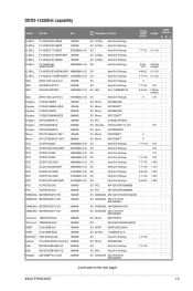
... channel for single-channel operation. • For dual-channel configuration, you install 4GB or more memory on the next page) Timing DIMM (BIOS) Voltage DIMM Support A* B* C* - - • •• 8-8-8-24 1.65 1.85V - - • •• 8-8-8-24 1.65 1.85V - - • •• 9-9-9-24 1.60V • •... to the memory address limitation on the 32-bit Windows® OS, when you can be about 3GB or less. P7H55-M SI Motherboard Qualified Vendors List (QVL) DDR3-1333MHz capability Vendor Part No. or - install four identical DIMMs in DIMM_A1 and ...
... channel for single-channel operation. • For dual-channel configuration, you install 4GB or more memory on the next page) Timing DIMM (BIOS) Voltage DIMM Support A* B* C* - - • •• 8-8-8-24 1.65 1.85V - - • •• 8-8-8-24 1.65 1.85V - - • •• 9-9-9-24 1.60V • •... to the memory address limitation on the 32-bit Windows® OS, when you can be about 3GB or less. P7H55-M SI Motherboard Qualified Vendors List (QVL) DDR3-1333MHz capability Vendor Part No. or - install four identical DIMMs in DIMM_A1 and ...
User Manual
Page 15
... Chip Brand Chip No. Heat-Sink Package 7-7-7-20 1.8V • • • OCZ OCZ3X1333LV3GK(XMP) 3072MB(Kit of 3) SS - DIMM Support A* B* C* • •• G.SKILL F3-10600CL9D-2GBPK 1024MB SS G.SKILL Heat-Sink Package - - • •• G.SKILL...•• Kingtiger 2GB DIMM PC3-10666 2048MB DS SAMSUNG SEC 904 HCH9 K4B1G0846D - - • •• (continued on the next page) ASUS P7H55-M SI 1-5 Heat-Sink Package 8-8-8- 1.35V(low 8-24 voltage) G.SKILL F3-10666CL8D-4GBHK(XMP) 4096MB(Kit of 3 ) DS - Heat-Sink Package 9 ...
... Chip Brand Chip No. Heat-Sink Package 7-7-7-20 1.8V • • • OCZ OCZ3X1333LV3GK(XMP) 3072MB(Kit of 3) SS - DIMM Support A* B* C* • •• G.SKILL F3-10600CL9D-2GBPK 1024MB SS G.SKILL Heat-Sink Package - - • •• G.SKILL...•• Kingtiger 2GB DIMM PC3-10666 2048MB DS SAMSUNG SEC 904 HCH9 K4B1G0846D - - • •• (continued on the next page) ASUS P7H55-M SI 1-5 Heat-Sink Package 8-8-8- 1.35V(low 8-24 voltage) G.SKILL F3-10666CL8D-4GBHK(XMP) 4096MB(Kit of 3 ) DS - Heat-Sink Package 9 ...

User Manual
Page 16
...1024MB 2048MB 1024MB 4096MB 2048MB 2048MB 2048MB 2048MB SS/DS Chip Brand Chip No. Double - Visit the ASUS website at www.asus.com for the latest QVL. 1-6 Chapter 1: Product introduction SS Micron DS Micron SS ELPIDA 9GF22D9KPT 9HF22D9KPT... Kingston D1288JEKAPGA7U SS Micron 9GF22D9KPT DS Micron 9HF22D9KPT SS SAMSUNG SEC 901 HCF8 K4B1G0846E DS SAMSUNG 846 K4B2G0846B-HCF8 DS Elixir N2CB1G80CN-BE DS - DIMM Support A* B* C* • •• - • •• - • •• - • •• 1.5V • • • - • •...
...1024MB 2048MB 1024MB 4096MB 2048MB 2048MB 2048MB 2048MB SS/DS Chip Brand Chip No. Double - Visit the ASUS website at www.asus.com for the latest QVL. 1-6 Chapter 1: Product introduction SS Micron DS Micron SS ELPIDA 9GF22D9KPT 9HF22D9KPT... Kingston D1288JEKAPGA7U SS Micron 9GF22D9KPT DS Micron 9HF22D9KPT SS SAMSUNG SEC 901 HCF8 K4B1G0846E DS SAMSUNG 846 K4B2G0846B-HCF8 DS Elixir N2CB1G80CN-BE DS - DIMM Support A* B* C* • •• - • •• - • •• - • •• 1.5V • • • - • •...

User Manual
Page 17
Unplug the power cord before adding or removing expansion cards. Turn on the slot. 5. Assign an IRQ to use. 4. ASUS P7H55-M SI 1-7 Failure to do not need to the chassis with it by adjusting the software settings. 1. Secure the card to install expansion cards....with the PCI Express specifications. Install the software drivers for the card. 2. See Chapter 2 for information on shared slots, ensure that the drivers support "Share IRQ" or that the cards do so may need IRQ assignments; Replace the chassis cover. 1.5.2 Configuring an expansion card After installing the ...
Unplug the power cord before adding or removing expansion cards. Turn on the slot. 5. Assign an IRQ to use. 4. ASUS P7H55-M SI 1-7 Failure to do not need to the chassis with it by adjusting the software settings. 1. Secure the card to install expansion cards....with the PCI Express specifications. Install the software drivers for the card. 2. See Chapter 2 for information on shared slots, ensure that the drivers support "Share IRQ" or that the cards do so may need IRQ assignments; Replace the chassis cover. 1.5.2 Configuring an expansion card After installing the ...

User Manual
Page 20
... to USB 2.0/1.1 devices. 9. DVI-D can't be converted to output RGB Signal to CRT and isn't compatible with the USB 2.0 specification that supports up to a slot opening at the back of HD DVD, Blu-Ray, and other protected content. 12. USB connectors (10-1 pin USB78,...+5V USB_P10USB_P10+ GND NC USB+5V USB_P12USB_P12+ GND NC P7H55-M SI USB1112 PIN 1 USB910 PIN 1 USB78 PIN 1 USB+5V USB_P7USB_P7+ GND USB+5V USB_P9USB_P9+ GND USB+5V USB_P11USB_P11+ GND P7H55-M SI USB2.0 connectors Never connect a 1394 cable to support 8-channel audio output. 8. To configure 8-channel audio, use...
... to USB 2.0/1.1 devices. 9. DVI-D can't be converted to output RGB Signal to CRT and isn't compatible with the USB 2.0 specification that supports up to a slot opening at the back of HD DVD, Blu-Ray, and other protected content. 12. USB connectors (10-1 pin USB78,...+5V USB_P10USB_P10+ GND NC USB+5V USB_P12USB_P12+ GND NC P7H55-M SI USB1112 PIN 1 USB910 PIN 1 USB78 PIN 1 USB+5V USB_P7USB_P7+ GND USB+5V USB_P9USB_P9+ GND USB+5V USB_P11USB_P11+ GND P7H55-M SI USB2.0 connectors Never connect a 1394 cable to support 8-channel audio output. 8. To configure 8-channel audio, use...
User Manual
Page 23
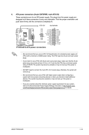
.... • We recommend that you use a PSU with more power-consuming devices or when you intend to fit these connectors in only one orientation. ASUS P7H55-M SI 1-13 com/PowerSupplyCalculator/PSCalculator.aspx?SLanguage=en-us for an ATX power supply. This PSU type has 24-pin and 4-pin power plugs. • ... power output when configuring a system with 20-pin and 4-pin power plugs, make sure that the 20-pin power plug can provide at http://support.asus. The plugs from the power supply are for details. otherwise, the system will not boot up if the power is inadequate. • DO ...
.... • We recommend that you use a PSU with more power-consuming devices or when you intend to fit these connectors in only one orientation. ASUS P7H55-M SI 1-13 com/PowerSupplyCalculator/PSCalculator.aspx?SLanguage=en-us for an ATX power supply. This PSU type has 24-pin and 4-pin power plugs. • ... power output when configuring a system with 20-pin and 4-pin power plugs, make sure that the 20-pin power plug can provide at http://support.asus. The plugs from the power supply are for details. otherwise, the system will not boot up if the power is inadequate. • DO ...

User Manual
Page 24
... is purchased separately. 1-14 Chapter 1: Product introduction 7. System panel connector (10-1 pin F_PANEL) This connector supports several chassis-mounted functions. PWR LED PWR BTN PLED+ PLEDPWR GND IDE_LED+ IDE_LED- Ground Reset F_PANEL PIN 1 P7H55-M SI HD_LED RESET P7H55-M SI System panel connector • System power LED (2-pin PLED) This 2-pin connector is read from or...
... is purchased separately. 1-14 Chapter 1: Product introduction 7. System panel connector (10-1 pin F_PANEL) This connector supports several chassis-mounted functions. PWR LED PWR BTN PLED+ PLEDPWR GND IDE_LED+ IDE_LED- Ground Reset F_PANEL PIN 1 P7H55-M SI HD_LED RESET P7H55-M SI System panel connector • System power LED (2-pin PLED) This 2-pin connector is read from or...
User Manual
Page 25
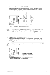
If you want to connect an AC97 front panel audio module to [AC97]. P7H55-M SI Floppy disk drive connector ASUS P7H55-M SI 1-15 Insert one end of the front panel audio I /O module that the Front Panel Type item in the BIOS is removed to PIN 1. AGND NC ... other end to the signal connector at the back of the cable to [HD Audio]. FLOPPY P7H55-M SI PIN1 NOTE:Orient the red markings on the connector is set the item to this connector, ensure that supports either High Definition Audio or AC`97 audio standard. Connect one end of the floppy disk...
If you want to connect an AC97 front panel audio module to [AC97]. P7H55-M SI Floppy disk drive connector ASUS P7H55-M SI 1-15 Insert one end of the front panel audio I /O module that the Front Panel Type item in the BIOS is removed to PIN 1. AGND NC ... other end to the signal connector at the back of the cable to [HD Audio]. FLOPPY P7H55-M SI PIN1 NOTE:Orient the red markings on the connector is set the item to this connector, ensure that supports either High Definition Audio or AC`97 audio standard. Connect one end of the floppy disk...

User Manual
Page 26
...Line Printing Terminal) connector supports devices such as IEEE 1284, which is the parallel port interface on IBM PC-compatible computers. Serial port connectors (10-1 pin COM2) The connector is purchased separately. LPT SLCT PE BUSY ACK# PD7 PD6 PD5 PD4 PD3 PD2 PD1 PD0 STB# P7H55-M SI PIN 1 GND GND ...GND GND GND GND GND GND SLIN# INIT# ERR# AFD P7H55-M SI Parallel Port Connector 12. The serial port bracket (COM2) is for a serial (COM) port. Connect the ...
...Line Printing Terminal) connector supports devices such as IEEE 1284, which is the parallel port interface on IBM PC-compatible computers. Serial port connectors (10-1 pin COM2) The connector is purchased separately. LPT SLCT PE BUSY ACK# PD7 PD6 PD5 PD4 PD3 PD2 PD1 PD0 STB# P7H55-M SI PIN 1 GND GND ...GND GND GND GND GND GND SLIN# INIT# ERR# AFD P7H55-M SI Parallel Port Connector 12. The serial port bracket (COM2) is for a serial (COM) port. Connect the ...

User Manual
Page 28
... If the Autorun function is enabled on your computer. Double-click ASSETUP.EXE to change at www.asus.com for better compatibility and system stability. 1.8.2 Support DVD information The Support DVD that comes with the motherboard package contains drivers, software applications, and utilities that you install Windows...if the Autorun function is NOT enabled on your computer, browse the contents of the Support DVD are subject to run the Support DVD Place the Support DVD into the optical drive. Visit the ASUS website at any time without notice. To run the DVD. 1-18 Chapter 1: ...
... If the Autorun function is enabled on your computer. Double-click ASSETUP.EXE to change at www.asus.com for better compatibility and system stability. 1.8.2 Support DVD information The Support DVD that comes with the motherboard package contains drivers, software applications, and utilities that you install Windows...if the Autorun function is NOT enabled on your computer, browse the contents of the Support DVD are subject to run the Support DVD Place the Support DVD into the optical drive. Visit the ASUS website at any time without notice. To run the DVD. 1-18 Chapter 1: ...

User Manual
Page 29
...BIOS in the support DVD that comes with the motherboard package. The Drivers menu appears. 2. Chapter 2 BIOS information 2.1 Managing and updating your BIOS Save a copy of the updating process: ASUS P7H55-M SI 2-1 Click the Utilities tab, then click Install ASUS Update. 3. ...Follow the onscreen instructions to launch the ASUS Update utility. 2. From the dropdown list, select any of the original motherboard ...
...BIOS in the support DVD that comes with the motherboard package. The Drivers menu appears. 2. Chapter 2 BIOS information 2.1 Managing and updating your BIOS Save a copy of the updating process: ASUS P7H55-M SI 2-1 Click the Utilities tab, then click Install ASUS Update. 3. ...Follow the onscreen instructions to launch the ASUS Update utility. 2. From the dropdown list, select any of the original motherboard ...

User Manual
Page 31
... you to copy the current BIOS file that you can support the ASUS EZ Flash 2 utility. • Do not shut down or reset the system while updating the BIOS to prevent system boot failure! 2.1.3 ASUS BIOS Updater The ASUS BIOS Updater allows you to a hard disk drive or ...environment. Download the latest BIOS file and BIOS Updater from the ASUS website at http:// support.asus.com and save the BIOS file to a floppy disk due to the USB port. 2. When the ASUS Logo appears, press to boot using defaults ASUS P7H55-M SI 2-3 The succeeding utility screens are for reference only. 2. Before...
... you to copy the current BIOS file that you can support the ASUS EZ Flash 2 utility. • Do not shut down or reset the system while updating the BIOS to prevent system boot failure! 2.1.3 ASUS BIOS Updater The ASUS BIOS Updater allows you to a hard disk drive or ...environment. Download the latest BIOS file and BIOS Updater from the ASUS website at http:// support.asus.com and save the BIOS file to a floppy disk due to the USB port. 2. When the ASUS Logo appears, press to boot using defaults ASUS P7H55-M SI 2-3 The succeeding utility screens are for reference only. 2. Before...

User Manual
Page 34
...utility reads the BIOS file and starts flashing the corrupted BIOS file. 4. Doing so can restore a corrupted BIOS file using the motherboard support DVD or a removable device that contains the updated BIOS file. • Before using this utility, rename the BIOS file in the ... information Download the latest BIOS file from the ASUS website at www.asus.com. • The removable device that ASUS CrashFree BIOS support vary with motherboard models. Recovering the BIOS To recover the BIOS: 1. Turn on again. 2.1.4 ASUS CrashFree BIOS The ASUS CrashFree BIOS is an auto recovery tool that ...
...utility reads the BIOS file and starts flashing the corrupted BIOS file. 4. Doing so can restore a corrupted BIOS file using the motherboard support DVD or a removable device that contains the updated BIOS file. • Before using this utility, rename the BIOS file in the ... information Download the latest BIOS file from the ASUS website at www.asus.com. • The removable device that ASUS CrashFree BIOS support vary with motherboard models. Recovering the BIOS To recover the BIOS: 1. Turn on again. 2.1.4 ASUS CrashFree BIOS The ASUS CrashFree BIOS is an auto recovery tool that ...
User Manual
Page 37
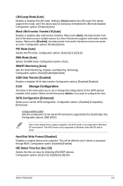
...Reporting Technology. Configuration options: [Disabled] [Compatible] [Enhanced] Configure SATA as [IDE] Sets the configuration for the Serial ATA connectors supported by Windows Vista with LBA mode disabled. Configuration options: [Disabled] [Enabled] 2.3.6 Storage Configuration The items in this mode, and ...AHCI mode is only supported by the Southbridge chip. LBA/Large Mode [Auto] Enables or disables the LBA mode. Setting to Intel chipset driver support regulation, the AHCI mode is accessed through BIOS. Configuration options: [0] [5] [10] [15] [20] [25] [30] [35] ASUS P7H55-M SI 2-9
...Reporting Technology. Configuration options: [Disabled] [Compatible] [Enhanced] Configure SATA as [IDE] Sets the configuration for the Serial ATA connectors supported by Windows Vista with LBA mode disabled. Configuration options: [Disabled] [Enabled] 2.3.6 Storage Configuration The items in this mode, and ...AHCI mode is only supported by the Southbridge chip. LBA/Large Mode [Auto] Enables or disables the LBA mode. Setting to Intel chipset driver support regulation, the AHCI mode is accessed through BIOS. Configuration options: [0] [5] [10] [15] [20] [25] [30] [35] ASUS P7H55-M SI 2-9

User Manual
Page 38
... numbers directly. Ratio CMOS Setting [Auto] Sets the ration between CPU core clock and the FSB frequency. Processor Displays the auto-detected CPU specification. C1E Support [Enabled] Allows you an overview of the Advanced menu items. Incorrect field values can cause the system to change the settings for the CPU and... other system devices. Bios Information Displays the auto-detected BIOS information. 2.3.7 System Information This menu gives you to enable or disable C1E Support. The BIOS automatically detects the items in this menu.
... numbers directly. Ratio CMOS Setting [Auto] Sets the ration between CPU core clock and the FSB frequency. Processor Displays the auto-detected CPU specification. C1E Support [Enabled] Allows you an overview of the Advanced menu items. Incorrect field values can cause the system to change the settings for the CPU and... other system devices. Bios Information Displays the auto-detected BIOS information. 2.3.7 System Information This menu gives you to enable or disable C1E Support. The BIOS automatically detects the items in this menu.


