
User Manual
Page 3
Contents Notices...v Safety information vi About this guide vi P7H55-M SI specifications summary viii Chapter 1: Product introduction 1.1 Before you proceed 1-1 1.2 Motherboard overview 1-2 1.2.1 Motherboard layout 1-2 1.2.2 Layout contents 1-2 1.3 Central... 1.7.2 Internal connectors 1-10 1.8 Software support 1-18 1.8.1 Installing an operating system 1-18 1.8.2 Support DVD information 1-18 Chapter 2: BIOS information 2.1 Managing and updating your BIOS 2-1 2.1.1 ASUS Update utility 2-1 2.1.2 ASUS EZ Flash 2 utility 2-2 2.1.3 ASUS BIOS Updater 2-3 2.1.4 ASUS CrashFree BIOS 2-6 iii
Contents Notices...v Safety information vi About this guide vi P7H55-M SI specifications summary viii Chapter 1: Product introduction 1.1 Before you proceed 1-1 1.2 Motherboard overview 1-2 1.2.1 Motherboard layout 1-2 1.2.2 Layout contents 1-2 1.3 Central... 1.7.2 Internal connectors 1-10 1.8 Software support 1-18 1.8.1 Installing an operating system 1-18 1.8.2 Support DVD information 1-18 Chapter 2: BIOS information 2.1 Managing and updating your BIOS 2-1 2.1.1 ASUS Update utility 2-1 2.1.2 ASUS EZ Flash 2 utility 2-2 2.1.3 ASUS BIOS Updater 2-3 2.1.4 ASUS CrashFree BIOS 2-6 iii

User Manual
Page 6
.... If you detect any area where it may become wet. • Place the product on it supports. • Chapter 2: BIOS information This chapter tells how to change system settings through the BIOS setup menus. Operation safety • Before installing the motherboard and adding devices on a stable surface. • If you are using... company. • If the power supply is organized This guide contains the following parts: • Chapter 1: Product introduction This chapter describes the features of the BIOS parameters are also provided.
.... If you detect any area where it may become wet. • Place the product on it supports. • Chapter 2: BIOS information This chapter tells how to change system settings through the BIOS setup menus. Operation safety • Before installing the motherboard and adding devices on a stable surface. • If you are using... company. • If the power supply is organized This guide contains the following parts: • Chapter 1: Product introduction This chapter describes the features of the BIOS parameters are also provided.

User Manual
Page 9
ix P7H55-M SI specifications summary Back Panel I/O Ports Internal I/O Connectors BIOS Manageability Accessories Support DVD Form Factor 1 x PS/2 Keyboard port 1 x PS/2 Mouse port 1 x HDMI port 1 x DVI port 1 x VGA port 1 x COM port 1 x RJ45 port 6 x USB 2.0/1.1 ports 3..., DMI2.0, WfM2.0, SM BIOS 2.5, ACPI2.0a, Multi-language BIOS WOL, PXE, PME Wake up, WOR by Ring 1 x UltraDMA 133/100 cable 2 x Serial ATA 3.0Gb/s cables 1 x I/O shield 1 x Support DVD 1 x User Manual Drivers ASUS PC Probe II ASUS Update Anti-Virus software (OEM version) uATX form factor: 9.6 in x 9.6 in (24.4cm x 24.4cm) *...
ix P7H55-M SI specifications summary Back Panel I/O Ports Internal I/O Connectors BIOS Manageability Accessories Support DVD Form Factor 1 x PS/2 Keyboard port 1 x PS/2 Mouse port 1 x HDMI port 1 x DVI port 1 x VGA port 1 x COM port 1 x RJ45 port 6 x USB 2.0/1.1 ports 3..., DMI2.0, WfM2.0, SM BIOS 2.5, ACPI2.0a, Multi-language BIOS WOL, PXE, PME Wake up, WOR by Ring 1 x UltraDMA 133/100 cable 2 x Serial ATA 3.0Gb/s cables 1 x I/O shield 1 x Support DVD 1 x User Manual Drivers ASUS PC Probe II ASUS Update Anti-Virus software (OEM version) uATX form factor: 9.6 in x 9.6 in (24.4cm x 24.4cm) *...
User Manual
Page 12
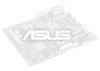
... CHA_FAN LGA1156 EATXPWR USB3_6 COM2 2 24.4cm(9.6in) LAN1_USB12 ICS 9LRS954 AUDIO RTL 8112L Super I/O PCIEX1_1 Lithium Cell CMOS Power PCIEX16 P7H55-M SI PCI1 Intel® GMA4500 SATA1 SATA2 7 8Mb BIOS 8 SATA3 SATA4 SATA5 SATA6 VIA VT1708S AAFP SPDIF_OUT LPT PCI2 17 16 15 FLOPPY USB1112 USB910 USB78 CHASSIS CLRTC 9 SB_PWR F_PANEL 14...
... CHA_FAN LGA1156 EATXPWR USB3_6 COM2 2 24.4cm(9.6in) LAN1_USB12 ICS 9LRS954 AUDIO RTL 8112L Super I/O PCIEX1_1 Lithium Cell CMOS Power PCIEX16 P7H55-M SI PCI1 Intel® GMA4500 SATA1 SATA2 7 8Mb BIOS 8 SATA3 SATA4 SATA5 SATA6 VIA VT1708S AAFP SPDIF_OUT LPT PCI2 17 16 15 FLOPPY USB1112 USB910 USB78 CHASSIS CLRTC 9 SB_PWR F_PANEL 14...

User Manual
Page 14
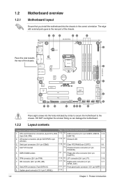
.... • This motherboard does not support DIMMs made up of 3) SS - Install a maximum of the following: - P7H55-M SI Motherboard Qualified Vendors List (QVL) DDR3-1333MHz capability Vendor Part No. A-Data A-Data AD31333001GOU AD31333G001GOU 1024MB SS A-Data 3072MB.... or - install four identical DIMMs in DIMM_A2 and DIMM_B2 (black slots). • Due to install 4GB or more memory on the next page) Timing DIMM (BIOS) Voltage DIMM Support A* B* C* - - • •• 8-8-8-24 1.65 1.85V - - • •• 8-8-8-24 1.65 1.85V - - • &#...
.... • This motherboard does not support DIMMs made up of 3) SS - Install a maximum of the following: - P7H55-M SI Motherboard Qualified Vendors List (QVL) DDR3-1333MHz capability Vendor Part No. A-Data A-Data AD31333001GOU AD31333G001GOU 1024MB SS A-Data 3072MB.... or - install four identical DIMMs in DIMM_A2 and DIMM_B2 (black slots). • Due to install 4GB or more memory on the next page) Timing DIMM (BIOS) Voltage DIMM Support A* B* C* - - • •• 8-8-8-24 1.65 1.85V - - • •• 8-8-8-24 1.65 1.85V - - • &#...
User Manual
Page 15
...8226; •• Kingtiger 2GB DIMM PC3-10666 2048MB DS SAMSUNG SEC 904 HCH9 K4B1G0846D - - • •• (continued on the next page) ASUS P7H55-M SI 1-5 Heat-Sink Package 8-8-8-21 1.5-1.6V • • • G.SKILL F3-10666CL7T-6GBPK(XMP) 6144MB(Kit of 3 ) DS - Heat-Sink Package...-Sink Package 7-7-7-20 1.75V • • • OCZ OCZ3G1333LV6GK 6144MB(Kit of 3) SS - SS G.SKILL Heat-Sink Package Timing DIMM (BIOS) - G.SKILL F3-10600CL8D-2GBHK Size 1024MB SS/ DS Chip Brand Chip No. Heat-Sink Package 7-7-7-20 1.65V • • • ...
...8226; •• Kingtiger 2GB DIMM PC3-10666 2048MB DS SAMSUNG SEC 904 HCH9 K4B1G0846D - - • •• (continued on the next page) ASUS P7H55-M SI 1-5 Heat-Sink Package 8-8-8-21 1.5-1.6V • • • G.SKILL F3-10666CL7T-6GBPK(XMP) 6144MB(Kit of 3 ) DS - Heat-Sink Package...-Sink Package 7-7-7-20 1.75V • • • OCZ OCZ3G1333LV6GK 6144MB(Kit of 3) SS - SS G.SKILL Heat-Sink Package Timing DIMM (BIOS) - G.SKILL F3-10600CL8D-2GBHK Size 1024MB SS/ DS Chip Brand Chip No. Heat-Sink Package 7-7-7-20 1.65V • • • ...

User Manual
Page 16
... 9GF22D9KPT DS Micron 9HF22D9KPT SS SAMSUNG SEC 901 HCF8 K4B1G0846E DS SAMSUNG 846 K4B2G0846B-HCF8 DS Elixir N2CB1G80CN-BE DS - Visit the ASUS website at www.asus.com for the latest QVL. 1-6 Chapter 1: Product introduction DIMM Support A* B* C* • •• - •...Sink Package Heat-Sink Package Heat-Sink Package Heat-Sink Package DDR3-1066MHz capability Timing DIMM (BIOS) 9 9-9-9-24 9 Voltage - Heat-Sink Package DS Elixir Heat-Sink Package DS Hynix H5TQ1G83AFP G7C Timing DIMM (BIOS) Voltage DIMM Support A* B* C* 7 - ••• 7 - •...
... 9GF22D9KPT DS Micron 9HF22D9KPT SS SAMSUNG SEC 901 HCF8 K4B1G0846E DS SAMSUNG 846 K4B2G0846B-HCF8 DS Elixir N2CB1G80CN-BE DS - Visit the ASUS website at www.asus.com for the latest QVL. 1-6 Chapter 1: Product introduction DIMM Support A* B* C* • •• - •...Sink Package Heat-Sink Package Heat-Sink Package Heat-Sink Package DDR3-1066MHz capability Timing DIMM (BIOS) 9 9-9-9-24 9 Voltage - Heat-Sink Package DS Elixir Heat-Sink Package DS Hynix H5TQ1G83AFP G7C Timing DIMM (BIOS) Voltage DIMM Support A* B* C* 7 - ••• 7 - •...

User Manual
Page 17
...the chassis with it by adjusting the software settings. 1. Remove the chassis cover (if your motherboard is completely seated on BIOS setup. 2. Assign an IRQ to use. 4. ASUS P7H55-M SI 1-7 Before installing the expansion card, read the documentation that comes with the screw. 6. Turn on shared slots, ensure ... and press firmly until the card is already installed in a chassis). 3. When using PCI cards on the system and change the necessary BIOS settings, if any. otherwise, conflicts will arise between the two PCI groups, making the system unstable and the card inoperable. 1.5.3 PCI ...
...the chassis with it by adjusting the software settings. 1. Remove the chassis cover (if your motherboard is completely seated on BIOS setup. 2. Assign an IRQ to use. 4. ASUS P7H55-M SI 1-7 Before installing the expansion card, read the documentation that comes with the screw. 6. Turn on shared slots, ensure ... and press firmly until the card is already installed in a chassis). 3. When using PCI cards on the system and change the necessary BIOS settings, if any. otherwise, conflicts will arise between the two PCI groups, making the system unstable and the card inoperable. 1.5.3 PCI ...
User Manual
Page 18
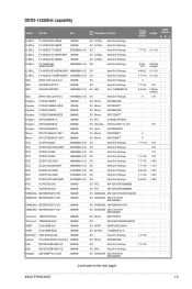
... in CMOS, which include system setup information such as system passwords. Hold down and cut off the AC power, then reboot the system, the BIOS automatically resets parameter settings to pins 1-2. 3. Clear RTC RAM (3-pin CLRTC) This jumper allows you to pins 2-3. For system failure due to clear...failure! • If the steps above do not need to clear the RTC when the system hangs due to reenter data. P7H55-M SI CLRTC 12 23 Normal (Default) Clear RTC P7H55-M SI Clear RTC RAM To erase the RTC RAM: 1. After clearing the CMOS, reinstall the battery. • You do not ...
... in CMOS, which include system setup information such as system passwords. Hold down and cut off the AC power, then reboot the system, the BIOS automatically resets parameter settings to pins 1-2. 3. Clear RTC RAM (3-pin CLRTC) This jumper allows you to pins 2-3. For system failure due to clear...failure! • If the steps above do not need to clear the RTC when the system hangs due to reenter data. P7H55-M SI CLRTC 12 23 Normal (Default) Clear RTC P7H55-M SI Clear RTC RAM To erase the RTC RAM: 1. After clearing the CMOS, reinstall the battery. • You do not ...
User Manual
Page 25
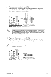
... back of the front panel audio I /O module that the Front Panel Type item in the BIOS is for details. 10. Floppy disk drive connector (34-1 pin FLOPPY) This connector is set the item to PIN 1. FLOPPY P7H55-M SI PIN1 NOTE:Orient the red markings on the connector is for a chassis-mounted front panel... prevent incorrect cable connection when using a FDD cable with a covered Pin 5. 9. Front panel audio connector (10-1 pin AAFP) This connector is removed to [HD Audio]. P7H55-M SI Floppy disk drive connector ASUS P7H55-M SI 1-15
... back of the front panel audio I /O module that the Front Panel Type item in the BIOS is for details. 10. Floppy disk drive connector (34-1 pin FLOPPY) This connector is set the item to PIN 1. FLOPPY P7H55-M SI PIN1 NOTE:Orient the red markings on the connector is for a chassis-mounted front panel... prevent incorrect cable connection when using a FDD cable with a covered Pin 5. 9. Front panel audio connector (10-1 pin AAFP) This connector is removed to [HD Audio]. P7H55-M SI Floppy disk drive connector ASUS P7H55-M SI 1-15

User Manual
Page 29
... your BIOS Save a copy of the updating process: ASUS P7H55-M SI 2-1 Copy the original motherboard BIOS using this utility. Place the support DVD in the support DVD that allows you to manage, save, and update the motherboard BIOS in Windows® environment. • ASUS Update... that comes with the motherboard package. Click the Utilities tab, then click Install ASUS Update. 3. Updating the BIOS To update the BIOS: 1. From the Windows® desktop, click Start > Programs > ASUS > ASUSUpdate > ASUSUpdate to complete the installation. Quit all Windows® applications before...
... your BIOS Save a copy of the updating process: ASUS P7H55-M SI 2-1 Copy the original motherboard BIOS using this utility. Place the support DVD in the support DVD that allows you to manage, save, and update the motherboard BIOS in Windows® environment. • ASUS Update... that comes with the motherboard package. Click the Utilities tab, then click Install ASUS Update. 3. Updating the BIOS To update the BIOS: 1. From the Windows® desktop, click Start > Programs > ASUS > ASUSUpdate > ASUSUpdate to complete the installation. Quit all Windows® applications before...

User Manual
Page 30
...ASUS Update utility is found. Select Update BIOS from the Internet, then click Next. Locate the BIOS file from a BIOS file a. Go to the Tools menu to select EZ Flash 2 and press to avail all its features. ASUSTek EZ Flash 2 BIOS ROM Utility V4.10 FLASH TYPE: Winbond 25X/Q64 Current ROM BOARD: P7H55-M SI... VER: 0207 (H:00 B:06) DATE: 12/14/2009 Update ROM BOARD: Unknown VER: Unknown DATE: Unknown PATH: A:\ A: Note [Enter] Select or Load [Up/Down/Home/End] Move [Tab] Switch [B] Backup [V] Drive Info [ESC] Exit 2-2 Chapter 2: BIOS information From the...
...ASUS Update utility is found. Select Update BIOS from the Internet, then click Next. Locate the BIOS file from a BIOS file a. Go to the Tools menu to select EZ Flash 2 and press to avail all its features. ASUSTek EZ Flash 2 BIOS ROM Utility V4.10 FLASH TYPE: Winbond 25X/Q64 Current ROM BOARD: P7H55-M SI... VER: 0207 (H:00 B:06) DATE: 12/14/2009 Update ROM BOARD: Unknown VER: Unknown DATE: Unknown PATH: A:\ A: Note [Enter] Select or Load [Up/Down/Home/End] Move [Tab] Switch [B] Backup [V] Drive Info [ESC] Exit 2-2 Chapter 2: BIOS information From the...

User Manual
Page 31
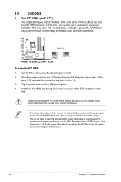
...8226; Do not shut down or reset the system while updating the BIOS to prevent system boot failure! 2.1.3 ASUS BIOS Updater The ASUS BIOS Updater allows you to copy the current BIOS file that you to update BIOS in NTFS format. • Do not save them on the USB ...flash drive. • NTFS is found, EZ Flash 2 performs the BIOS update process and automatically reboots the system when done. • Only a USB flash disk with the latest BIOS file and BIOS Updater to boot using defaults ASUS P7H55-M SI...
...8226; Do not shut down or reset the system while updating the BIOS to prevent system boot failure! 2.1.3 ASUS BIOS Updater The ASUS BIOS Updater allows you to copy the current BIOS file that you to update BIOS in NTFS format. • Do not save them on the USB ...flash drive. • NTFS is found, EZ Flash 2 performs the BIOS update process and automatically reboots the system when done. • Only a USB flash disk with the latest BIOS file and BIOS Updater to boot using defaults ASUS P7H55-M SI...

User Manual
Page 32
... Disk menu appears, select the FreeDOS command prompt item by pressing the item number. 4. At the FreeDOS prompt, type bupdater /o[filename] and press . ASUSTek BIOS Updater for the extension. 2. At the FreeDOS prompt, type d: and press to switch the disk from Drive C (optical drive) to the DOS prompt. ...characters for DOS V1.00b [09/06/22] FLASH TYPE:Winbond 25X/Q64 Current ROM BOARD: P7H55-M SI VER: 0207 DATE: 12/14/2009 Update ROM BOARD: Unknown VER: Unknown DATE: Unknown PATH: A:\ BIOS backup is not write-protected and has at least 1024KB free space to FreeDOS (http://www....
... Disk menu appears, select the FreeDOS command prompt item by pressing the item number. 4. At the FreeDOS prompt, type bupdater /o[filename] and press . ASUSTek BIOS Updater for the extension. 2. At the FreeDOS prompt, type d: and press to switch the disk from Drive C (optical drive) to the DOS prompt. ...characters for DOS V1.00b [09/06/22] FLASH TYPE:Winbond 25X/Q64 Current ROM BOARD: P7H55-M SI VER: 0207 DATE: 12/14/2009 Update ROM BOARD: Unknown VER: Unknown DATE: Unknown PATH: A:\ BIOS backup is not write-protected and has at least 1024KB free space to FreeDOS (http://www....

User Manual
Page 33
...shut down or reset the system while updating the BIOS to prevent system boot failure! • For BIOS Updater version 1.04 or later, the utility automatically exits to ensure system compatibility and stability. ASUS P7H55-M SI 2-5 ASUSTek BIOS Updater for details. • Ensure to connect all... SATA hard disk drives after updating BIOS. • Ensure to load the BIOS default settings to the DOS prompt after updating the BIOS file if you have disconnected ...
...shut down or reset the system while updating the BIOS to prevent system boot failure! • For BIOS Updater version 1.04 or later, the utility automatically exits to ensure system compatibility and stability. ASUS P7H55-M SI 2-5 ASUSTek BIOS Updater for details. • Ensure to connect all... SATA hard disk drives after updating BIOS. • Ensure to load the BIOS default settings to the DOS prompt after updating the BIOS file if you have disconnected ...

User Manual
Page 34
... using the motherboard support DVD or a removable device that ASUS CrashFree BIOS support vary with motherboard models. When found, the utility reads the BIOS file and starts flashing the corrupted BIOS file. 4. 2.1.4 ASUS CrashFree BIOS The ASUS CrashFree BIOS is an auto recovery tool that contains the BIOS file to the USB port or to the floppy disk drive...
... using the motherboard support DVD or a removable device that ASUS CrashFree BIOS support vary with motherboard models. When found, the utility reads the BIOS file and starts flashing the corrupted BIOS file. 4. 2.1.4 ASUS CrashFree BIOS The ASUS CrashFree BIOS is an auto recovery tool that contains the BIOS file to the USB port or to the floppy disk drive...

User Manual
Page 35
... compatibility and stability. If you do not press , POST continues with its parameters. ASUS P7H55-M SI 2-7 Entering BIOS Setup at startup To enter BIOS Setup at www.asus.com to download the latest BIOS file for most conditions to your screen. • Visit the ASUS website at startup: • Press during the Power-On Self Test (POST). If...
... compatibility and stability. If you do not press , POST continues with its parameters. ASUS P7H55-M SI 2-7 Entering BIOS Setup at startup To enter BIOS Setup at www.asus.com to download the latest BIOS file for most conditions to your screen. • Visit the ASUS website at startup: • Press during the Power-On Self Test (POST). If...

User Manual
Page 36
... 6 :[Not Detected] Storage Configuration System Information Use [ENTER], [TAB] or [SHIFT-TAB] to display the SATA device information. Main Advanced Power BIOS SETUP UTILITY Boot Tools Exit System Time System Date Legacy Diskette A Language [00:31:48] [Fri 04/10/2009] [1.44M, 3.5 in ...Use [+] or [-] to [Auto] allows automatic selection of the basic system information. These values are specifically configuring a CD-ROM drive. The BIOS automatically detects the values opposite the dimmed items (Device, Vendor, Size, LBA Mode, Block Mode, PIO Mode, Async DMA, Ultra DMA,...
... 6 :[Not Detected] Storage Configuration System Information Use [ENTER], [TAB] or [SHIFT-TAB] to display the SATA device information. Main Advanced Power BIOS SETUP UTILITY Boot Tools Exit System Time System Date Legacy Diskette A Language [00:31:48] [Fri 04/10/2009] [1.44M, 3.5 in ...Use [+] or [-] to [Auto] allows automatic selection of the basic system information. These values are specifically configuring a CD-ROM drive. The BIOS automatically detects the values opposite the dimmed items (Device, Vendor, Size, LBA Mode, Block Mode, PIO Mode, Async DMA, Ultra DMA,...
User Manual
Page 37
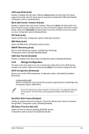
... Reporting Technology. Configuration options: [Disabled] [Compatible] [Enhanced] Configure SATA as [IDE] Sets the configuration for detecting ATA/ATAPI devices. The AHCI mode is accessed through BIOS. When set the SATA configuration. LBA/Large Mode [Auto] Enables or disables the LBA mode. Configuration options: [Disabled] [Auto] Block (Multi-sector Transfer) M [Auto] Enables... Configuration [Enhanced] Allows you to set to [Auto], the data transfer from and to configure the item. Configuration options: [0] [5] [10] [15] [20] [25] [30] [35] ASUS P7H55-M SI 2-9
... Reporting Technology. Configuration options: [Disabled] [Compatible] [Enhanced] Configure SATA as [IDE] Sets the configuration for detecting ATA/ATAPI devices. The AHCI mode is accessed through BIOS. When set the SATA configuration. LBA/Large Mode [Auto] Enables or disables the LBA mode. Configuration options: [Disabled] [Auto] Block (Multi-sector Transfer) M [Auto] Enables... Configuration [Enhanced] Allows you to set to [Auto], the data transfer from and to configure the item. Configuration options: [0] [5] [10] [15] [20] [25] [30] [35] ASUS P7H55-M SI 2-9

User Manual
Page 38
...and other system devices. Key in this menu show the CPU-related information that the BIOS automatically detects. Configuration options: [Disabled] [Enabled] 2-10 Chapter 2: BIOS information Processor Displays the auto-detected CPU specification. Take caution when changing the settings of... the general system specifications. If an invalid ratio is set values may differ. Main Advanced Power BIOS SETUP UTILITY Boot Tools Exit CPU Configuration Chipset Onboard Devices Configuration USB Configuration PCIPnP TPM Configuration Intel VT-d Configuration Configure...
...and other system devices. Key in this menu show the CPU-related information that the BIOS automatically detects. Configuration options: [Disabled] [Enabled] 2-10 Chapter 2: BIOS information Processor Displays the auto-detected CPU specification. Take caution when changing the settings of... the general system specifications. If an invalid ratio is set values may differ. Main Advanced Power BIOS SETUP UTILITY Boot Tools Exit CPU Configuration Chipset Onboard Devices Configuration USB Configuration PCIPnP TPM Configuration Intel VT-d Configuration Configure...


