
User Manual
Page 4
... window 4-9 4.2.8 Scroll bar 4-9 4.2.9 General help 4-9 4.3 Main menu 4-10 4.3.1 System Time 4-10 4.3.2 System Date 4-10 4.3.3 SATA1~4 4-11 4.3.4 Storage Configuration 4-12 4.3.5 System Information 4-13 4.4 Advanced menu 4-14 4.4.1 CPU Configuration 4-14 4.4.2 Chipset 4-16 4.4.3 Onboard Devices Configuration 4-18 4.4.4 USB Configuration 4-19 4.4.5 PCI PnP 4-20 4.5 Power menu 4-21 4.5.1 Suspend Mode 4-21 4.5.2 ACPI 2.0 Support 4-21 4.5.3 ACPI APIC...
... window 4-9 4.2.8 Scroll bar 4-9 4.2.9 General help 4-9 4.3 Main menu 4-10 4.3.1 System Time 4-10 4.3.2 System Date 4-10 4.3.3 SATA1~4 4-11 4.3.4 Storage Configuration 4-12 4.3.5 System Information 4-13 4.4 Advanced menu 4-14 4.4.1 CPU Configuration 4-14 4.4.2 Chipset 4-16 4.4.3 Onboard Devices Configuration 4-18 4.4.4 USB Configuration 4-19 4.4.5 PCI PnP 4-20 4.5 Power menu 4-21 4.5.1 Suspend Mode 4-21 4.5.2 ACPI 2.0 Support 4-21 4.5.3 ACPI APIC...
User Manual
Page 32
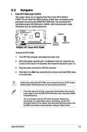
The onboard button cell battery powers the RAM data in CMOS. Move the jumper cap from pins 1-2 (default) to overclocking, use the CPU Parameter Recall (C.P.R.) feature. Turn OFF the computer and unplug the power cord. 2. After clearing the CMOS, reinstall the battery. • You do not ...CLRTC 12 23 P5QPL10T Clear RTC RAM Normal (Default) Clear RTC To erase the RTC RAM: 1. Keep the cap on CLRTC jumper default position. ASUS P6-P5G41E 3-3 Removing the cap will cause system boot failure! • If the steps above do not need to clear the RTC when the system hangs due...
The onboard button cell battery powers the RAM data in CMOS. Move the jumper cap from pins 1-2 (default) to overclocking, use the CPU Parameter Recall (C.P.R.) feature. Turn OFF the computer and unplug the power cord. 2. After clearing the CMOS, reinstall the battery. • You do not ...CLRTC 12 23 P5QPL10T Clear RTC RAM Normal (Default) Clear RTC To erase the RTC RAM: 1. Keep the cap on CLRTC jumper default position. ASUS P6-P5G41E 3-3 Removing the cap will cause system boot failure! • If the steps above do not need to clear the RTC when the system hangs due...
User Manual
Page 33
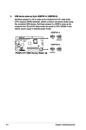
USBPW1-4 12 23 P5QPL10T +5V +5VSB (Default) USBPW5-6 12 23 +5V +5VSB P5QPL10T USB Device Wake Up (Default) 3-4 Chapter 3: Motherboard info 2. Set these jumpers to +5V to wake up the compurer from S3 and S4 sleep modes (no power to wake up the computer from S1 sleep mode (CPU stopped, DRAM refreshed, system running in reduced power mode). USB device wake-up (3-pin USBPW1-4, USBPW5-6) Set these jumpers to +5VSB to CPU, DRAM in slow refresh, power supply in low power mode) using the connected USB devices.
USBPW1-4 12 23 P5QPL10T +5V +5VSB (Default) USBPW5-6 12 23 +5V +5VSB P5QPL10T USB Device Wake Up (Default) 3-4 Chapter 3: Motherboard info 2. Set these jumpers to +5V to wake up the compurer from S3 and S4 sleep modes (no power to wake up the computer from S1 sleep mode (CPU stopped, DRAM refreshed, system running in reduced power mode). USB device wake-up (3-pin USBPW1-4, USBPW5-6) Set these jumpers to +5VSB to CPU, DRAM in slow refresh, power supply in low power mode) using the connected USB devices.
User Manual
Page 34
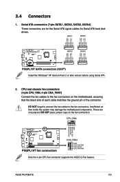
... PWR GND P5QPL10T P5QPL10T fan connectors CHA_FAN1 GND CPU FAN PWR CPU FAN IN CPU FAN PWM Only the 4-pin CPU fan connector supports the ASUS Q-Fan feature. CPU and chassis fan connectors. (4-pin CPU_FAN, 4-pin CHA_FAN1) Connect the fan cables to the fan connectors. DO NOT place jumper caps ... 2 or later version before using Serial ATA. 2. DO NOT forget to connect the fan cables to the fan connectors on the fan connectors! ASUS P6-P5G41E 3-5 These are for the Serial ATA signal cables for Serial ATA hard disk drives. Serial ATA connectors (7-pin SATA1, SATA2, SATA3, SATA4) ...
... PWR GND P5QPL10T P5QPL10T fan connectors CHA_FAN1 GND CPU FAN PWR CPU FAN IN CPU FAN PWM Only the 4-pin CPU fan connector supports the ASUS Q-Fan feature. CPU and chassis fan connectors. (4-pin CPU_FAN, 4-pin CHA_FAN1) Connect the fan cables to the fan connectors. DO NOT place jumper caps ... 2 or later version before using Serial ATA. 2. DO NOT forget to connect the fan cables to the fan connectors on the fan connectors! ASUS P6-P5G41E 3-5 These are for the Serial ATA signal cables for Serial ATA hard disk drives. Serial ATA connectors (7-pin SATA1, SATA2, SATA3, SATA4) ...
User Manual
Page 50
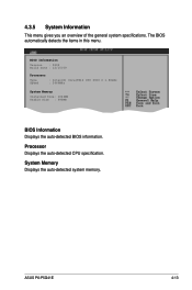
System Memory Displays the auto-detected system memory. Processor Displays the auto-detected CPU specification. 4.3.5 System Information This menu gives you an overview of the general system specifications. BIOS Information Version : 0202 Build Date : 12/15/09 Processor Type Speed : Intel(R) Core(TM)2 CPU 6300 @ 1.86GHz : 2666MHz System Memory Installed Size: 1024MB Usable Size : 990MB BIOS Information Displays the auto-detected BIOS information. The BIOS automatically detects the items in this menu. ASUS P6-P5G41E 4-13
System Memory Displays the auto-detected system memory. Processor Displays the auto-detected CPU specification. 4.3.5 System Information This menu gives you an overview of the general system specifications. BIOS Information Version : 0202 Build Date : 12/15/09 Processor Type Speed : Intel(R) Core(TM)2 CPU 6300 @ 1.86GHz : 2666MHz System Memory Installed Size: 1024MB Usable Size : 990MB BIOS Information Displays the auto-detected BIOS information. The BIOS automatically detects the items in this menu. ASUS P6-P5G41E 4-13

User Manual
Page 51
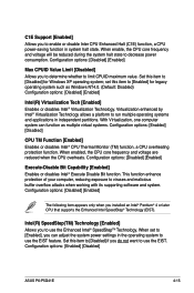
... to malfunction. EFFEEFFEn11Sn11St0Ct0Ceerr GSGSESSSGGSEoeeaxeeeoeaxlnvilllnviteeeteeeteetocrcccortaatttaaSlnSlnuSdISIudbcHtctbHreEere-eESelxmemslxcepiecpirntnrteeeenn v02.61 (C)Copyright 1985-2009, American Megatrends, Inc. 4.4.1 CPU Configuration The items in order to enable or disable the "Enhanced Halt State". 4-14 Chapter ... (Min:06, Max:08) Ratio Actual Value: 8 CPUID : 6F9 C1E Support Max CPUID Value Limit Intel(R) Virtualization Tech CPU TM Function: Execute-Disable Bit Capability Intel(R)SpeedStep(TM) Tech Intel(R) C-STATE Tech [Enabled] [Disabled] [Enabled] [Enabled]...
... to malfunction. EFFEEFFEn11Sn11St0Ct0Ceerr GSGSESSSGGSEoeeaxeeeoeaxlnvilllnviteeeteeeteetocrcccortaatttaaSlnSlnuSdISIudbcHtctbHreEere-eESelxmemslxcepiecpirntnrteeeenn v02.61 (C)Copyright 1985-2009, American Megatrends, Inc. 4.4.1 CPU Configuration The items in order to enable or disable the "Enhanced Halt State". 4-14 Chapter ... (Min:06, Max:08) Ratio Actual Value: 8 CPUID : 6F9 C1E Support Max CPUID Value Limit Intel(R) Virtualization Tech CPU TM Function: Execute-Disable Bit Capability Intel(R)SpeedStep(TM) Tech Intel(R) C-STATE Tech [Enabled] [Disabled] [Enabled] [Enabled]...
User Manual
Page 52
...® Virtualization Technology allows a platform to run multiple operating systems and applications in system halt state. When enabled, the CPU core frequency and voltage are reduced when the CPU overheats. Configuration options: [Enabled] [Disabled] ASUS P6-P5G41E 4-15 Set this item to [Enabled] for Windows XP operating system; When set this item to [Disabled] for...
...® Virtualization Technology allows a platform to run multiple operating systems and applications in system halt state. When enabled, the CPU core frequency and voltage are reduced when the CPU overheats. Configuration options: [Enabled] [Disabled] ASUS P6-P5G41E 4-15 Set this item to [Enabled] for Windows XP operating system; When set this item to [Disabled] for...

User Manual
Page 53
... disable the Intel® C-STATE Technology. North Bridge Configuration Configure North Bridge features. Select an item then press to C2/C3/C4. When enabled, the CPU idle is set to display the sub-menu. Intel(R) C-STATE Tech [disabled] Allows you to select the graphics controller as the primary boot device. Configuration...
... disable the Intel® C-STATE Technology. North Bridge Configuration Configure North Bridge features. Select an item then press to C2/C3/C4. When enabled, the CPU idle is set to display the sub-menu. Intel(R) C-STATE Tech [disabled] Allows you to select the graphics controller as the primary boot device. Configuration...

User Manual
Page 60
... field shows N/A. The onboard hardware monitor automatically detects and displays the CPU / motherboard temperatures. Select Ignored if you to display the detected temperatures. 4.5.5 Hardware Monitor Hardware Monitor CPU Temperature MB Temperature CPU Fan Speed Chassis Fan Speed Smart Q-Fan Function VCORE Voltage 3.3V ...monitor automatically detects the voltage output through the onboard voltage regulators. ASUS P6-P5G41E 4-23 Select Ignored if you do not wish to Sub-screen F1 General Help F10 Save and Exit ESC Exit CPU/MB Temperature [xxxºC/xxxºF] or [Ignored]. Select ...
... field shows N/A. The onboard hardware monitor automatically detects and displays the CPU / motherboard temperatures. Select Ignored if you to display the detected temperatures. 4.5.5 Hardware Monitor Hardware Monitor CPU Temperature MB Temperature CPU Fan Speed Chassis Fan Speed Smart Q-Fan Function VCORE Voltage 3.3V ...monitor automatically detects the voltage output through the onboard voltage regulators. ASUS P6-P5G41E 4-23 Select Ignored if you do not wish to Sub-screen F1 General Help F10 Save and Exit ESC Exit CPU/MB Temperature [xxxºC/xxxºF] or [Ignored]. Select ...


