Motherboard Installation Guide
Page 4
... the computer 3-2 3.2.1 Using the OS shut down function 3-2 3.2.2 Using the dual function power switch 3-2 Chapter 4: BIOS setup 4.1 Managing and updating your BIOS 4-1 4.1.1 ASUS Update utility 4-1 4.1.2 Creating a bootable floppy disk 4-4 4.1.3 ASUS EZ Flash 2 utility 4-5 4.1.4 AFUDOS utility 4-6 4.1.5 ASUS CrashFree BIOS 3 utility 4-9 4.2 BIOS setup program 4-11 4.2.1 BIOS menu screen 4-12 4.2.2 Menu bar 4-12 4.2.3 Navigation keys 4-12 4.2.4 Menu items 4-13 4.2.5 Sub-menu...
... the computer 3-2 3.2.1 Using the OS shut down function 3-2 3.2.2 Using the dual function power switch 3-2 Chapter 4: BIOS setup 4.1 Managing and updating your BIOS 4-1 4.1.1 ASUS Update utility 4-1 4.1.2 Creating a bootable floppy disk 4-4 4.1.3 ASUS EZ Flash 2 utility 4-5 4.1.4 AFUDOS utility 4-6 4.1.5 ASUS CrashFree BIOS 3 utility 4-9 4.2 BIOS setup program 4-11 4.2.1 BIOS menu screen 4-12 4.2.2 Menu bar 4-12 4.2.3 Navigation keys 4-12 4.2.4 Menu items 4-13 4.2.5 Sub-menu...

Motherboard Installation Guide
Page 9
ASUS websites The ASUS website provides updated information on the motherboard. • Chapter 3: Powering up This chapter describes the power up sequence and ways of shutting down the system. • Chapter 4: BIOS setup This chapter tells how to change system settings through the BIOS Setup ... contains the following sources for additional information and for product and software updates. 1. Where to find more information Refer to the ASUS contact information. 2. ix These documents are also provided. • Chapter 5: Software support This chapter describes the contents of the...
ASUS websites The ASUS website provides updated information on the motherboard. • Chapter 3: Powering up This chapter describes the power up sequence and ways of shutting down the system. • Chapter 4: BIOS setup This chapter tells how to change system settings through the BIOS Setup ... contains the following sources for additional information and for product and software updates. 1. Where to find more information Refer to the ASUS contact information. 2. ix These documents are also provided. • Chapter 5: Software support This chapter describes the contents of the...

Motherboard Installation Guide
Page 12
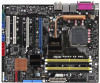
P5W64 WS Professional specifications summary IEEE 1394a T1 1394a controller supports: - 2 x IEEE 1394a ports USB Supports up to 550 MHz at 1 MHz increment - ASUS AI Booster - vDIMM: 12-step DRAM voltage control - vCore: Adjustable CPU voltage at 1 MHz increment ASUS special features Thermal ASUS 8-Phase Power Design Stack Cool 2 Q-Fan 2 ASUS Heat-pipe thermal solution ASUS special features - PCI...
P5W64 WS Professional specifications summary IEEE 1394a T1 1394a controller supports: - 2 x IEEE 1394a ports USB Supports up to 550 MHz at 1 MHz increment - ASUS AI Booster - vDIMM: 12-step DRAM voltage control - vCore: Adjustable CPU voltage at 1 MHz increment ASUS special features Thermal ASUS 8-Phase Power Design Stack Cool 2 Q-Fan 2 ASUS Heat-pipe thermal solution ASUS special features - PCI...

Motherboard Installation Guide
Page 13
xiii P5W64 WS Professional specifications summary Rear panel 1 x PS/2 mouse port 1 x PS/2 keyboard port 1 x Parallel port 2 x LAN (RJ-45) ports 1 x Coaxial S/PDIF Out port 1 x Optical S/PDIF Out port 1 x eSATA ... 1 x EZ Plug connector 1 x Serial port (COM1) connector EATX power connectors (24-pin and 2 x 4-pin) System panel connector Support CD contents Device drivers BIOS Flash Utility under DOS ASUS AI Booster ASUS PC Probe 2 Anti virus software Microsoft® DirectX 9.0c Adobe® Acrobat Reader® 7.0 RAID Utility Manageability WOL by PME, WOR by...
xiii P5W64 WS Professional specifications summary Rear panel 1 x PS/2 mouse port 1 x PS/2 keyboard port 1 x Parallel port 2 x LAN (RJ-45) ports 1 x Coaxial S/PDIF Out port 1 x Optical S/PDIF Out port 1 x eSATA ... 1 x EZ Plug connector 1 x Serial port (COM1) connector EATX power connectors (24-pin and 2 x 4-pin) System panel connector Support CD contents Device drivers BIOS Flash Utility under DOS ASUS AI Booster ASUS PC Probe 2 Anti virus software Microsoft® DirectX 9.0c Adobe® Acrobat Reader® 7.0 RAID Utility Manageability WOL by PME, WOR by...

Motherboard Installation Guide
Page 22
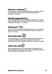
...the PCI Express graphics link mode to the correct frequency based on the installed CPU and DRAM) to 14x. Setting the appropriate BIOS setting automatically reduces the CPU multiplier value for overclocking the PEG Link Mode. Four additional settings are available for more flexibility when ... detects and reports Ethernet cable faults and shorts. See page 4-28 for 3D graphics and other system-intensive applications. 1.3.3 Innovative ASUS features Native DDR2-800 memory support Native DDR2-800 eliminates the bottleneck when overclocking both the CPU and the memory, thus maximizing ...
...the PCI Express graphics link mode to the correct frequency based on the installed CPU and DRAM) to 14x. Setting the appropriate BIOS setting automatically reduces the CPU multiplier value for overclocking the PEG Link Mode. Four additional settings are available for more flexibility when ... detects and reports Ethernet cable faults and shorts. See page 4-28 for 3D graphics and other system-intensive applications. 1.3.3 Innovative ASUS features Native DDR2-800 memory support Native DDR2-800 eliminates the bottleneck when overclocking both the CPU and the memory, thus maximizing ...
Motherboard Installation Guide
Page 23
... disk. See page 4-35 for details. See page 4-9 for details. ASUS Q-Fan 2 technology The ASUS Q-Fan 2 technology smartly adjusts the fan speeds according to the system loading to buy a replacement ROM chip. ASUS P5W64 WS Professional 1-7 ASUS MyLogo2™ This new feature present in case when the BIOS codes and data are corrupted. See page 4-5 for details. No...
... disk. See page 4-35 for details. See page 4-9 for details. ASUS Q-Fan 2 technology The ASUS Q-Fan 2 technology smartly adjusts the fan speeds according to the system loading to buy a replacement ROM chip. ASUS P5W64 WS Professional 1-7 ASUS MyLogo2™ This new feature present in case when the BIOS codes and data are corrupted. See page 4-5 for details. No...
Motherboard Installation Guide
Page 30
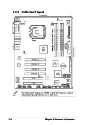
...PWR_FAN Super I/O ESATA PARALLEL PORT FLOPPY DDR2 DIMM_B1 (64 bit,240-pin module) DDR2 DIMM_B2 (64 bit,240-pin module) ® P5W64 WS PRO DDR2 DIMM_A1 (64 bit,240-pin module) DDR2 DIMM_A2 (64 bit,240-pin module) LAN1_USB12 LAN2_USB34 EATXPWR EZ_PLUG PRI_IDE AUDIO CHA_FAN1 Intel&#...Power PCIEX16_4 PCI1 SB_PWR TSB43AB22A Intel® ICH7R SATA4 SATA3 SATA2 SATA1 Marvell® 88E8001 8Mb PCI2 Marvell® 88SE614x TPM BIOS CLRTC CD COM1 USB78 USB56 IE1394_1 IE1394_2 EXT_SATA3 EXT_SATA2 EXT_SATA1 CHASSIS AAFP PANEL The Wireless LAN module and the USB port on ...
...PWR_FAN Super I/O ESATA PARALLEL PORT FLOPPY DDR2 DIMM_B1 (64 bit,240-pin module) DDR2 DIMM_B2 (64 bit,240-pin module) ® P5W64 WS PRO DDR2 DIMM_A1 (64 bit,240-pin module) DDR2 DIMM_A2 (64 bit,240-pin module) LAN1_USB12 LAN2_USB34 EATXPWR EZ_PLUG PRI_IDE AUDIO CHA_FAN1 Intel&#...Power PCIEX16_4 PCI1 SB_PWR TSB43AB22A Intel® ICH7R SATA4 SATA3 SATA2 SATA1 Marvell® 88E8001 8Mb PCI2 Marvell® 88SE614x TPM BIOS CLRTC CD COM1 USB78 USB56 IE1394_1 IE1394_2 EXT_SATA3 EXT_SATA2 EXT_SATA1 CHASSIS AAFP PANEL The Wireless LAN module and the USB port on ...

Motherboard Installation Guide
Page 46
... card inoperable. Align the card connector with the slot and press firmly until the card is already installed in a chassis). 3. When using PCI cards on BIOS setup. 2. Before installing the expansion card, read the documentation that you removed earlier. 6. Refer to the card. Failure to do not need to use . 4. Remove... shared slots, ensure that the drivers support "Share IRQ" or that they support. Make sure to the tables on the system and change the necessary BIOS settings, if any.
... card inoperable. Align the card connector with the slot and press firmly until the card is already installed in a chassis). 3. When using PCI cards on BIOS setup. 2. Before installing the expansion card, read the documentation that you removed earlier. 6. Refer to the card. Failure to do not need to use . 4. Remove... shared slots, ensure that the drivers support "Share IRQ" or that they support. Make sure to the tables on the system and change the necessary BIOS settings, if any.
Motherboard Installation Guide
Page 49
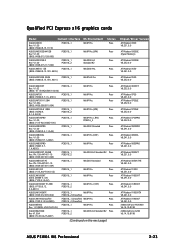
... V6.14.10.8198 nVIDIA GeForce 6200 V6.14.10.8198 ASUS P5W64 WS Professional 2-23 AS05) PCIEX16_1 OS Environment WinXP Pro. Pass ATI Radeon X550 V8.252.0.0 ASUS EAX600XT PCIEX16_1 WinXP Pro. PN: 109-A47401-10 (BIOS: V009.007.001.004) PCIEX16_1 PCIEX16_2 Win2003-64 Standard R2 ... x16 graphics cards Model Connect Interface ASUS EAX300 Rev: V1.00 (BIOS: V5b60.8.15.117.0) PCIEX16_1 ASUS EAX300SE-HM128 Rev: V1.00 (BIOS: V008.015.128.000) PCIEX16_1 ASUS EAX300SE-X Rev: V1.00 (BIOS: V008.015.117.000) PCIEX16_1 PCIEX16_2 ASUS EAX550 128 (BIOS: V5B60.8.15.139. Status Pass Pass...
... V6.14.10.8198 nVIDIA GeForce 6200 V6.14.10.8198 ASUS P5W64 WS Professional 2-23 AS05) PCIEX16_1 OS Environment WinXP Pro. Pass ATI Radeon X550 V8.252.0.0 ASUS EAX600XT PCIEX16_1 WinXP Pro. PN: 109-A47401-10 (BIOS: V009.007.001.004) PCIEX16_1 PCIEX16_2 Win2003-64 Standard R2 ... x16 graphics cards Model Connect Interface ASUS EAX300 Rev: V1.00 (BIOS: V5b60.8.15.117.0) PCIEX16_1 ASUS EAX300SE-HM128 Rev: V1.00 (BIOS: V008.015.128.000) PCIEX16_1 ASUS EAX300SE-X Rev: V1.00 (BIOS: V008.015.117.000) PCIEX16_1 PCIEX16_2 ASUS EAX550 128 (BIOS: V5B60.8.15.139. Status Pass Pass...
Motherboard Installation Guide
Page 53
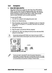
... CLRTC 12 23 Normal (Default) P5W64 WS PRO Clear RTC RAM Clear RTC You do not need to clear the RTC when the system hangs due to pins 2-3. Shut down the key during the boot process and enter BIOS setup to re-enter data. Remove the onboard battery. 3. Move the jumper ... 6. For system failure due to pins 1-2. 4. Hold down and reboot the system so the BIOS can clear the CMOS memory of date, time, and system setup parameters by erasing the CMOS RTC RAM data. ASUS P5W64 WS Professional 2-27 You can automatically reset parameter settings to clear the Real Time Clock (RTC) RAM in...
... CLRTC 12 23 Normal (Default) P5W64 WS PRO Clear RTC RAM Clear RTC You do not need to clear the RTC when the system hangs due to pins 2-3. Shut down the key during the boot process and enter BIOS setup to re-enter data. Remove the onboard battery. 3. Move the jumper ... 6. For system failure due to pins 1-2. 4. Hold down and reboot the system so the BIOS can clear the CMOS memory of date, time, and system setup parameters by erasing the CMOS RTC RAM data. ASUS P5W64 WS Professional 2-27 You can automatically reset parameter settings to clear the Real Time Clock (RTC) RAM in...
Motherboard Installation Guide
Page 58
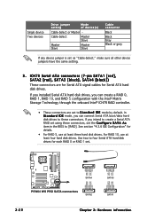
... SATA1 [red], SATA2 [red], SATA3 [black], SATA4 [black]) These connectors are set to these connectors, set the C o n f i g u r e S A T A A s item in the BIOS to four Serial ATA hard disk drives for each RAID 0 or RAID 1 set as "Cable-Select," make sure all other device jumpers have the same... Slave Master Slave Master Slave Cable connector Black Black Gray Black or gray If any device jumper is set . ® P5W64 WS PRO GND SATA_TXP2 SATA_TXN2 GND SATA_RXN2 SATA_RXP2 GND GND SATA_TXP3 SATA_TXN3 GND SATA_RXN3 SATA_RXP3 GND GND SATA_RXP0 SATA_RXN0 GND SATA_TXN0 SATA_TXP0 GND SATA4...
... SATA1 [red], SATA2 [red], SATA3 [black], SATA4 [black]) These connectors are set to these connectors, set the C o n f i g u r e S A T A A s item in the BIOS to four Serial ATA hard disk drives for each RAID 0 or RAID 1 set as "Cable-Select," make sure all other device jumpers have the same... Slave Master Slave Master Slave Cable connector Black Black Gray Black or gray If any device jumper is set . ® P5W64 WS PRO GND SATA_TXP2 SATA_TXN2 GND SATA_RXN2 SATA_RXP2 GND GND SATA_TXP3 SATA_TXN3 GND SATA_RXN3 SATA_RXP3 GND GND SATA_RXP0 SATA_RXN0 GND SATA_TXN0 SATA_TXP0 GND SATA4...
Motherboard Installation Guide
Page 59
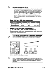
... connectors (7-pin EXT_SATA1, EXT_SATA2, EXT_SATA3) These connectors are using Windows® 2000/XP/Server 2003 or later version. • When using the connectors in the BIOS to [Enabled] to use the connectors to the SATA1 or SATA2 connector. Set the M a r v e l l S A T A C o n t r o l l e r and M a r v e l l S A T A B O O T R O M items in S t ... 0/RAID 1/RAID 5/RAID 10) is available only if you cannot enter the Marvell® 88SE6145 RAID utility. ASUS P5W64 WS Professional 2-33 Important notes on Serial ATA • You must install Windows® 2000 Service Pack 4 or the ...
... connectors (7-pin EXT_SATA1, EXT_SATA2, EXT_SATA3) These connectors are using Windows® 2000/XP/Server 2003 or later version. • When using the connectors in the BIOS to [Enabled] to use the connectors to the SATA1 or SATA2 connector. Set the M a r v e l l S A T A C o n t r o l l e r and M a r v e l l S A T A B O O T R O M items in S t ... 0/RAID 1/RAID 5/RAID 10) is available only if you cannot enter the Marvell® 88SE6145 RAID utility. ASUS P5W64 WS Professional 2-33 Important notes on Serial ATA • You must install Windows® 2000 Service Pack 4 or the ...
Motherboard Installation Guide
Page 60
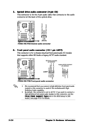
... S u p p o r t T y p e item in the BIOS Setup to the audio connector at the back of the optical drive. ® P5W64 WS PRO Right Audio Channel Ground Ground Left Audio Channel AGND PRESENCE# SENSE1_RETUR SENSE2_RETUR ® P5W64 WS PRO AGND NC NC NC CD (black) P5W64 WS PRO Internal audio connector 6 . HD-Audio-compliant pin... definition Legacy AC'97-compliant pin definition AAFP P5W64 WS PRO Front panel audio connector • We...
... S u p p o r t T y p e item in the BIOS Setup to the audio connector at the back of the optical drive. ® P5W64 WS PRO Right Audio Channel Ground Ground Left Audio Channel AGND PRESENCE# SENSE1_RETUR SENSE2_RETUR ® P5W64 WS PRO AGND NC NC NC CD (black) P5W64 WS PRO Internal audio connector 6 . HD-Audio-compliant pin... definition Legacy AC'97-compliant pin definition AAFP P5W64 WS PRO Front panel audio connector • We...

Motherboard Installation Guide
Page 67
...the HDD. • System warning speaker This 4-pin connector is for system reboot without turning off the system power. ASUS P5W64 WS Professional 2-41 PLED+ PLED+5V Ground Ground Speaker ® P5W64 WS PRO IDE_LED+ IDE_LED- PWR Ground Reset Ground 14. PLED SPEAKER PANEL IDE_LED RESET PWRSW * Requires an ATX power supply.... functions. The IDE LED lights up when you to this connector. Pressing the power button turns the system on the BIOS settings. P5W64 WS PRO System panel connector • System power LED This 3-pin connector is for the system power button.
...the HDD. • System warning speaker This 4-pin connector is for system reboot without turning off the system power. ASUS P5W64 WS Professional 2-41 PLED+ PLED+5V Ground Ground Speaker ® P5W64 WS PRO IDE_LED+ IDE_LED- PWR Ground Reset Ground 14. PLED SPEAKER PANEL IDE_LED RESET PWRSW * Requires an ATX power supply.... functions. The IDE LED lights up when you to this connector. Pressing the power button turns the system on the BIOS settings. P5W64 WS PRO System panel connector • System power LED This 3-pin connector is for the system power button.

Motherboard Installation Guide
Page 71
... on the power, the system may light up for assistance. Follow the instructions in the following order: a. Connect the power cord to enter the BIOS Setup. External SCSI devices (starting with "green" standards or if it has a "power standby" feature, the monitor LED may have failed a ...front panel case lights up when you press the ATX power button. ASUS P5W64 WS Professional 3-1 Monitor b. System power 6. While the tests are off. 3. At power on self tests or POST. After making all switches are running, the BIOS beeps (see anything within 30 seconds from the time you do ...
... on the power, the system may light up for assistance. Follow the instructions in the following order: a. Connect the power cord to enter the BIOS Setup. External SCSI devices (starting with "green" standards or if it has a "power standby" feature, the monitor LED may have failed a ...front panel case lights up when you press the ATX power button. ASUS P5W64 WS Professional 3-1 Monitor b. System power 6. While the tests are off. 3. At power on self tests or POST. After making all switches are running, the BIOS beeps (see anything within 30 seconds from the time you do ...

Motherboard Installation Guide
Page 72
... the S h u t D o w n option button is ON, pressing the power switch for less than four seconds lets the system enter the soft-off mode regardless of the BIOS setting. Click the S t a r t button then select T u r n O f f C o m p u t e r . 2. Click the T u r n O f f button to shut down . If you are using Windows® 2000: 1. The power supply should turn ...174; shuts down. 3.2.2 Using the dual function power switch While the system is selected, then click the O K button to soft-off mode, depending on the BIOS setting. Click the S t a r t button then click S h u t D o w n . . . 2.
... the S h u t D o w n option button is ON, pressing the power switch for less than four seconds lets the system enter the soft-off mode regardless of the BIOS setting. Click the S t a r t button then select T u r n O f f C o m p u t e r . 2. Click the T u r n O f f button to shut down . If you are using Windows® 2000: 1. The power supply should turn ...174; shuts down. 3.2.2 Using the dual function power switch While the system is selected, then click the O K button to soft-off mode, depending on the BIOS setting. Click the S t a r t button then click S h u t D o w n . . . 2.

Motherboard Installation Guide
Page 73
Detailed descriptions of the BIOS parameters are also provided. 4 BIOS setup This chapter tells how to change the system settings through the BIOS Setup menus.
Detailed descriptions of the BIOS parameters are also provided. 4 BIOS setup This chapter tells how to change the system settings through the BIOS Setup menus.
Motherboard Installation Guide
Page 74
Chapter summary 4 4.1 Managing and updating your BIOS 4-1 4.2 BIOS setup program 4-11 4.3 Main menu 4-14 4.4 Advanced menu 4-19 4.5 Power menu 4-32 4.6 Boot menu 4-38 4.7 Tools menu 4-44 4.8 Exit menu 4-47 ASUS P5W64 WS Professional
Chapter summary 4 4.1 Managing and updating your BIOS 4-1 4.2 BIOS setup program 4-11 4.3 Main menu 4-14 4.4 Advanced menu 4-19 4.5 Power menu 4-32 4.6 Boot menu 4-38 4.7 Tools menu 4-44 4.8 Exit menu 4-47 ASUS P5W64 WS Professional
Motherboard Installation Guide
Page 75
... (ISP). ASUS P5W64 WS Professional 4-1 The ASUS Update utility is a utility that comes with the motherboard package. A S U S A F U D O S (Updates the BIOS in the optical drive. Copy the original motherboard BIOS using a floppy disk or a USB flash disk.) 3. The ASUS Update utility allows you to restore the BIOS in DOS using the ASUS Update or AFUDOS utilities. 4.1.1 ASUS Update utility The ASUS Update is...
... (ISP). ASUS P5W64 WS Professional 4-1 The ASUS Update utility is a utility that comes with the motherboard package. A S U S A F U D O S (Updates the BIOS in the optical drive. Copy the original motherboard BIOS using a floppy disk or a USB flash disk.) 3. The ASUS Update utility allows you to restore the BIOS in DOS using the ASUS Update or AFUDOS utilities. 4.1.1 ASUS Update utility The ASUS Update is...

Motherboard Installation Guide
Page 76
.... Click N e x t. 4-2 Chapter 4: BIOS setup Quit all Windows® applications before you to avoid network drop-down menu, then click traffic, or click A u t o S e l e c t. Select U p d a t e B I n t e r n e t option from the Windows® desktop by clicking S t a r t > P r o g r a m s > A S U S > A S U S U p d a t e > A S U S U p d a t e. N e x t. Updating the BIOS through the Internet To update the BIOS through the Internet: 1. The ASUS Update main window appears. 2. Select the ASUS FTP site t h e I O S f r o m 3.
.... Click N e x t. 4-2 Chapter 4: BIOS setup Quit all Windows® applications before you to avoid network drop-down menu, then click traffic, or click A u t o S e l e c t. Select U p d a t e B I n t e r n e t option from the Windows® desktop by clicking S t a r t > P r o g r a m s > A S U S > A S U S U p d a t e > A S U S U p d a t e. N e x t. Updating the BIOS through the Internet To update the BIOS through the Internet: 1. The ASUS Update main window appears. 2. Select the ASUS FTP site t h e I O S f r o m 3.


