
Motherboard DIY Troubleshooting Guide
Page 3
... information vii About this guide viii P5VDC-MX specifications summary x Chapter 1: Product introduction 1.1 Welcome 1-2 1.2 Package contents 1-2 1.3 Special features 1-2 1.3.1 Product highlights 1-2 1.3.2 Innovative ASUS features 1-4 1.4 Before you proceed 1-5 1.5 Motherboard overview 1-6 1.5.1 Placement direction 1-6 1.5.2 Screw holes 1-6 1.5.3 Motherboard layout 1-7 1.6 Central Processing Unit (CPU 1-8 1.6.1 Installling the CPU 1-8 1.6.2 Installling the CPU heatsink and fan 1-11 1.6.3 Uninstalling the CPU heatsink and fan 1-13 1.7 System memory...
... information vii About this guide viii P5VDC-MX specifications summary x Chapter 1: Product introduction 1.1 Welcome 1-2 1.2 Package contents 1-2 1.3 Special features 1-2 1.3.1 Product highlights 1-2 1.3.2 Innovative ASUS features 1-4 1.4 Before you proceed 1-5 1.5 Motherboard overview 1-6 1.5.1 Placement direction 1-6 1.5.2 Screw holes 1-6 1.5.3 Motherboard layout 1-7 1.6 Central Processing Unit (CPU 1-8 1.6.1 Installling the CPU 1-8 1.6.2 Installling the CPU heatsink and fan 1-11 1.6.3 Uninstalling the CPU heatsink and fan 1-13 1.7 System memory...
Motherboard DIY Troubleshooting Guide
Page 4
...Internal connectors 1-26 Chapter 2: BIOS setup 2.1 Managing and updating your BIOS 2-2 2.1.1 Creating a bootable floppy disk 2-2 2.1.2 ASUS EZ Flash utility 2-3 2.1.3 AFUDOS utility 2-4 2.1.4 ASUS CrashFree BIOS 2 utility 2-6 2.1.5 ASUS Update utility 2-8 2.2 BIOS setup program 2-11 2.2.1 BIOS menu screen 2-12 2.2.2 Menu bar 2-12 2.2.3 Navigation keys 2-.../Slave 2-15 2.3.5 System Information 2-16 2.4 Advanced menu 2-17 2.4.1 JumperFree Configuration 2-17 2.4.2 USB Configuration 2-18 2.4.3 CPU Configuration 2-19 2.4.4 Chipset 2-20 2.4.5 Onboard Devices Configuration 2-24 iv
...Internal connectors 1-26 Chapter 2: BIOS setup 2.1 Managing and updating your BIOS 2-2 2.1.1 Creating a bootable floppy disk 2-2 2.1.2 ASUS EZ Flash utility 2-3 2.1.3 AFUDOS utility 2-4 2.1.4 ASUS CrashFree BIOS 2 utility 2-6 2.1.5 ASUS Update utility 2-8 2.2 BIOS setup program 2-11 2.2.1 BIOS menu screen 2-12 2.2.2 Menu bar 2-12 2.2.3 Navigation keys 2-.../Slave 2-15 2.3.5 System Information 2-16 2.4 Advanced menu 2-17 2.4.1 JumperFree Configuration 2-17 2.4.2 USB Configuration 2-18 2.4.3 CPU Configuration 2-19 2.4.4 Chipset 2-20 2.4.5 Onboard Devices Configuration 2-24 iv

Motherboard DIY Troubleshooting Guide
Page 10
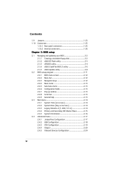
P5VDC-MX specifications summary CPU Chipset Front Side Bus Memory Expansion slots VGA Storage LAN Audio Other ASUS Special Features Back panel I/O Ports LGA775 socket for Intel® Pentium® D/Pentium® 4/ Celeron CPU Compatible with Intel® 05B/05A and 04B/ 04A processor ... 133/100/66 4 x Serial ATA 3Gb/s with RAID 0, 1, 0+1 & JBOD function Realtek RTL8201CL 10/100 LAN controller Realtek ALC653 AC'97 6-channel Audio CODEC ASUS Q-Fan ASUS EZ Flash CrashFree BIOS 2 ASUS MyLogo 1 x Parallel port 1 x RJ-45 4 x USB 2.0/1.1 1 x VGA out 1 x Serial port 1 x PS/2 keyboard 1 x PS/2 mouse ...
P5VDC-MX specifications summary CPU Chipset Front Side Bus Memory Expansion slots VGA Storage LAN Audio Other ASUS Special Features Back panel I/O Ports LGA775 socket for Intel® Pentium® D/Pentium® 4/ Celeron CPU Compatible with Intel® 05B/05A and 04B/ 04A processor ... 133/100/66 4 x Serial ATA 3Gb/s with RAID 0, 1, 0+1 & JBOD function Realtek RTL8201CL 10/100 LAN controller Realtek ALC653 AC'97 6-channel Audio CODEC ASUS Q-Fan ASUS EZ Flash CrashFree BIOS 2 ASUS MyLogo 1 x Parallel port 1 x RJ-45 4 x USB 2.0/1.1 1 x VGA out 1 x Serial port 1 x PS/2 keyboard 1 x PS/2 mouse ...
Motherboard DIY Troubleshooting Guide
Page 11
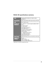
P5VDC-MX specifications summary BIOS 4 Mb Flash ROM, AMI BIOS, PnP, WfM2.0, DMI2.0, SM BIOS 2.3 Manageability WOL by PME, WOR by PME, Chassis Intrussion, PXE, RPL USB Internal I/O connectors Max. 8 USB 2.0 ports 2 x USB 2.0/1.1 connector supports additional 4 USB ports 4 x SATA connector 2 x IDE connector CPU/Chassis fan ... connector System panel connector Form Factor mATX Form Factor, 9.6 in x 9.6 in (24.5 cm x 24.5 cm) Support CD contents Drivers ASUS PC Probe ASUS Live Update utility Anti-virus software (OEM version) *Specifications are subject to change without notice. xi
P5VDC-MX specifications summary BIOS 4 Mb Flash ROM, AMI BIOS, PnP, WfM2.0, DMI2.0, SM BIOS 2.3 Manageability WOL by PME, WOR by PME, Chassis Intrussion, PXE, RPL USB Internal I/O connectors Max. 8 USB 2.0 ports 2 x USB 2.0/1.1 connector supports additional 4 USB ports 4 x SATA connector 2 x IDE connector CPU/Chassis fan ... connector System panel connector Form Factor mATX Form Factor, 9.6 in x 9.6 in (24.5 cm x 24.5 cm) Support CD contents Drivers ASUS PC Probe ASUS Live Update utility Anti-virus software (OEM version) *Specifications are subject to change without notice. xi
Motherboard DIY Troubleshooting Guide
Page 15
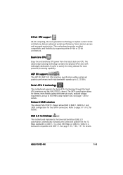
... AGP 8X (AGP 3.0) VGA interface specification enables enhanced graphics performance with individually dedicated L2 cache to 300 MB/s data transfer rate. ASUS P5VDC-MX 1-3 The advanced processing technology contains two physical CPU cores with high bandwidth speeds up to satisfy the rising demand for details. This motherboard provides excellent compatibility and flexibility by supporting...
... AGP 8X (AGP 3.0) VGA interface specification enables enhanced graphics performance with individually dedicated L2 cache to 300 MB/s data transfer rate. ASUS P5VDC-MX 1-3 The advanced processing technology contains two physical CPU cores with high bandwidth speeds up to satisfy the rising demand for details. This motherboard provides excellent compatibility and flexibility by supporting...

Motherboard DIY Troubleshooting Guide
Page 16
... CrashFree BIOS 2 This feature allows you can easily update the system BIOS even before loading the operating system. ASUS EZ Flash BIOS With the ASUS EZ Flash, you to use a DOS-based utility or boot from the support CD in case when the BIOS codes and data... are corrupted. See page 2-3 for deails. 1-4 Chapter 1: Product introduction ASUS Q-Fan technology The ASUS Q-Fan technology smartly adjusts the CPU fan speed according to the system loading to buy a replacement ROM chip. See page 2-30 for details. This protection eliminates...
... CrashFree BIOS 2 This feature allows you can easily update the system BIOS even before loading the operating system. ASUS EZ Flash BIOS With the ASUS EZ Flash, you to use a DOS-based utility or boot from the support CD in case when the BIOS codes and data... are corrupted. See page 2-3 for deails. 1-4 Chapter 1: Product introduction ASUS Q-Fan technology The ASUS Q-Fan technology smartly adjusts the CPU fan speed according to the system loading to buy a replacement ROM chip. See page 2-30 for details. This protection eliminates...

Motherboard DIY Troubleshooting Guide
Page 20
...® Pentium® D processor in this section do not match the CPU documentation, follow the latter. • Upon purchase of the PnP cap. • Due to the PnP cap/socket pins/motherboard components. ASUS will shoulder the cost of repair only if the damage is on the LGA775... shipment/ transit-related. • Keep the cap after installing the motherboard. Locate the CPU socket on the socket and the socket pins are not bent. P5VDC-MX ® P5VDC-MX CPU Socket 775 Before installing the CPU, make sure that the socket box is facing towards you see any damage to chipset...
...® Pentium® D processor in this section do not match the CPU documentation, follow the latter. • Upon purchase of the PnP cap. • Due to the PnP cap/socket pins/motherboard components. ASUS will shoulder the cost of repair only if the damage is on the LGA775... shipment/ transit-related. • Keep the cap after installing the motherboard. Locate the CPU socket on the socket and the socket pins are not bent. P5VDC-MX ® P5VDC-MX CPU Socket 775 Before installing the CPU, make sure that the socket box is facing towards you see any damage to chipset...

Motherboard DIY Troubleshooting Guide
Page 21
...Cap B This side of the socket. Load plate 5. Gold triangle mark ASUS P5VDC-MX A 1-9 Lift the load plate with your thumb and forefinger to a 100º angle (A), then push the PnP cap B from the retention tab. Position the CPU over the socket, making sure that the gold triangle is released from ... left (B) until it is on the bottom-left corner of the cam box should fit A l i g n m e n t k e y into the CPU notch. The socket alignment key should face you are installing a CPU. 3. Lift the load lever in the direction of the arrow to the socket pins, do not remove the PnP cap...
...Cap B This side of the socket. Load plate 5. Gold triangle mark ASUS P5VDC-MX A 1-9 Lift the load plate with your thumb and forefinger to a 100º angle (A), then push the PnP cap B from the retention tab. Position the CPU over the socket, making sure that the gold triangle is released from ... left (B) until it is on the bottom-left corner of the cam box should fit A l i g n m e n t k e y into the CPU notch. The socket alignment key should face you are installing a CPU. 3. Lift the load lever in the direction of the arrow to the socket pins, do not remove the PnP cap...
Motherboard DIY Troubleshooting Guide
Page 22
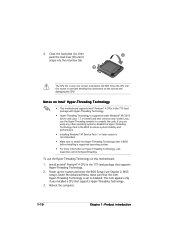
... the BIOS Setup (see Chapter 2: BIOS setup). Reboot the computer. 1-10 Chapter 1: Product introduction Install an Intel® Pentium® 4 CPU in the 775-land package with Hyper-Threading Technology. • Hyper-Threading Technology is supported under Windows® XP/2003 Server and Linux 1.7.x ...XP Service Pack 1 or later version is set to enable the Hyper-Threading Technology item in only one correct orientation. If you installed a CPU that supports Hyper-Threading Technology. 2. Close the load plate (A), then A push the load lever (B) until it snaps into the socket ...
... the BIOS Setup (see Chapter 2: BIOS setup). Reboot the computer. 1-10 Chapter 1: Product introduction Install an Intel® Pentium® 4 CPU in the 775-land package with Hyper-Threading Technology. • Hyper-Threading Technology is supported under Windows® XP/2003 Server and Linux 1.7.x ...XP Service Pack 1 or later version is set to enable the Hyper-Threading Technology item in only one correct orientation. If you installed a CPU that supports Hyper-Threading Technology. 2. Close the load plate (A), then A push the load lever (B) until it snaps into the socket ...

Motherboard DIY Troubleshooting Guide
Page 23
... 4 LGA775 heatsink and fan assembly comes in a push-pin design and requires no tool to install. To install the CPU heatsink and fan: 1. 1.6.2 Installling the CPU heatsink and fan The Intel® Pentium® 4/Pentium® D LGA775 processor requires a specially designed heatsink and fan ... hole Make sure each fastener is properly applied to the CPU heatsink or CPU before you install the CPU fan and heatsink assembly • When you buy a CPU separately, make sure that a Thermal Interface Material is oriented as shown, with the narrow groove directed outward. ASUS P5VDC-MX 1-11
... 4 LGA775 heatsink and fan assembly comes in a push-pin design and requires no tool to install. To install the CPU heatsink and fan: 1. 1.6.2 Installling the CPU heatsink and fan The Intel® Pentium® 4/Pentium® D LGA775 processor requires a specially designed heatsink and fan ... hole Make sure each fastener is properly applied to the CPU heatsink or CPU before you install the CPU fan and heatsink assembly • When you buy a CPU separately, make sure that a Thermal Interface Material is oriented as shown, with the narrow groove directed outward. ASUS P5VDC-MX 1-11

Motherboard DIY Troubleshooting Guide
Page 24
CPU_FAN GND CPU FAN PWR CPU FAN IN CPU FAN PWM ® P5VDC-MX CPU fan connector Do not forget to plug this connector. 1-12 Chapter 1: Product introduction When the fan and heatsink assembly is in place. Hardware monitoring errors can occur if you fail to connect the CPU fan connector! 2. Push down two fasteners at a time in a diagonal sequence to secure the heatsink and fan B assembly in place, connect the CPU fan cable to the connector on the motherboard labeled CPU_FAN. A A A B B B A P5VDC-MX 3.
CPU_FAN GND CPU FAN PWR CPU FAN IN CPU FAN PWM ® P5VDC-MX CPU fan connector Do not forget to plug this connector. 1-12 Chapter 1: Product introduction When the fan and heatsink assembly is in place. Hardware monitoring errors can occur if you fail to connect the CPU fan connector! 2. Push down two fasteners at a time in a diagonal sequence to secure the heatsink and fan B assembly in place, connect the CPU fan cable to the connector on the motherboard labeled CPU_FAN. A A A B B B A P5VDC-MX 3.

Motherboard DIY Troubleshooting Guide
Page 25
Rotate each fastener counterclockwise. 3. B A B B A ASUS P5VDC-MX 1-13 Disconnect the CPU fan cable from the A A motherboard. 1.6.3 Uninstalling the CPU heatsink and fan To uninstall the CPU heatsink and fan: 1. Pull up two fasteners at a time in a diagonal sequence to disengage the heatsink B and fan assembly from the connector on the motherboard labeled CPU_FAN. 2.
Rotate each fastener counterclockwise. 3. B A B B A ASUS P5VDC-MX 1-13 Disconnect the CPU fan cable from the A A motherboard. 1.6.3 Uninstalling the CPU heatsink and fan To uninstall the CPU heatsink and fan: 1. Pull up two fasteners at a time in a diagonal sequence to disengage the heatsink B and fan assembly from the connector on the motherboard labeled CPU_FAN. 2.

Motherboard DIY Troubleshooting Guide
Page 35
... data. Shut down the key during the boot process and enter BIOS setup to overclocking, use the C.P.R. (CPU Parameter Recall) feature. The onboard button cell battery powers the RAM data in CMOS. P5VDC-MX ® P5VDC-MX Clear RTC RAM CLRTC 12 23 Normal (Default) CLEAR You do not need to clear the RTC when... the cap will cause system boot failure! Clear RTC RAM (CLRTC) This jumper allows you to pins 2-3. For system failure due to re-enter data. ASUS P5VDC-MX 1-23
... data. Shut down the key during the boot process and enter BIOS setup to overclocking, use the C.P.R. (CPU Parameter Recall) feature. The onboard button cell battery powers the RAM data in CMOS. P5VDC-MX ® P5VDC-MX Clear RTC RAM CLRTC 12 23 Normal (Default) CLEAR You do not need to clear the RTC when... the cap will cause system boot failure! Clear RTC RAM (CLRTC) This jumper allows you to pins 2-3. For system failure due to re-enter data. ASUS P5VDC-MX 1-23
Motherboard DIY Troubleshooting Guide
Page 36
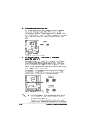
... KBPWR 12 23 +5V (Default) +5VSB P5VDC-MX ® P5VDC-MX Keyboard power setting 3. USB device wake-up (3-pin USBPW12, USBPW34, USBPW56, USBPW78) Set these jumpers to +5V to CPU, DRAM in slow refresh, power supply in sleep mode. USBPW12 USBPW34 12 23 P5VDC-MX +5V (Default) +5VSB USBPW56 ® ...USBPW78 12 23 1-24 P5VDC-MX USB device wake-up +5V (Default) +5VSB • The USB ...
... KBPWR 12 23 +5V (Default) +5VSB P5VDC-MX ® P5VDC-MX Keyboard power setting 3. USB device wake-up (3-pin USBPW12, USBPW34, USBPW56, USBPW78) Set these jumpers to +5V to CPU, DRAM in slow refresh, power supply in sleep mode. USBPW12 USBPW34 12 23 P5VDC-MX +5V (Default) +5VSB USBPW56 ® ...USBPW78 12 23 1-24 P5VDC-MX USB device wake-up +5V (Default) +5VSB • The USB ...

Motherboard DIY Troubleshooting Guide
Page 41
... ground pin of the connector. P5VDC-MX SPDIF_OUT ® GND SPDIFOUT +5V P5VDC-MX Digital audio connector The S/PDIF out module is for the S/PDIF audio module to the fan connectors on the fan connectors. ASUS P5VDC-MX 1-29 5. Insufficient air flow ...inside the system may damage the motherboard components. Digital Audio connector (4-1 pin SPDIF) This connector is purchased separately. Do not forget to connect the fan cables to the S/PDIF module. These are not jumpers! CPU_FAN GND CPU FAN PWR CPU FAN IN CPU FAN PWM P5VDC-MX...
... ground pin of the connector. P5VDC-MX SPDIF_OUT ® GND SPDIFOUT +5V P5VDC-MX Digital audio connector The S/PDIF out module is for the S/PDIF audio module to the fan connectors on the fan connectors. ASUS P5VDC-MX 1-29 5. Insufficient air flow ...inside the system may damage the motherboard components. Digital Audio connector (4-1 pin SPDIF) This connector is purchased separately. Do not forget to connect the fan cables to the S/PDIF module. These are not jumpers! CPU_FAN GND CPU FAN PWR CPU FAN IN CPU FAN PWM P5VDC-MX...

Motherboard DIY Troubleshooting Guide
Page 62
..., Analysis, and Reporting Technology. PIO Mode [Auto] Selects the PIO mode. AMIBIOS Version : 0110 Build Date : 10/05/05 Processor Type Speed Count : Genuine Intel(R) CPU 3.80GHz : 3914 MHz : 1 System Memory Usable Size : 192MB AMI BIOS Displays the auto-detected BIOS information Processor Displays the auto-detected...
..., Analysis, and Reporting Technology. PIO Mode [Auto] Selects the PIO mode. AMIBIOS Version : 0110 Build Date : 10/05/05 Processor Type Speed Count : Genuine Intel(R) CPU 3.80GHz : 3914 MHz : 1 System Memory Usable Size : 192MB AMI BIOS Displays the auto-detected BIOS information Processor Displays the auto-detected...

Motherboard DIY Troubleshooting Guide
Page 63
... will be stable. Select either one of this item is auto-detected by the clock generator to achieve desired CPU internal frequency. loads the optimal settings for the CPU and other system devices. CPU Frequency [200 MHz] Displays the frequency sent by the BIOS. The value of the preset overclocking configuration options: M a n u ... to 400. Overclock Mode [Auto] Allows selection of the Advanced menu items. Incorrect field values may cause the system to adjust the CPU frequency. Use the < + > and < - > keys to malfunction. ASUS P5VDC-MX 2-17 You can also type the desired...
... will be stable. Select either one of this item is auto-detected by the clock generator to achieve desired CPU internal frequency. loads the optimal settings for the CPU and other system devices. CPU Frequency [200 MHz] Displays the frequency sent by the BIOS. The value of the preset overclocking configuration options: M a n u ... to 400. Overclock Mode [Auto] Allows selection of the Advanced menu items. Incorrect field values may cause the system to adjust the CPU frequency. Use the < + > and < - > keys to malfunction. ASUS P5VDC-MX 2-17 You can also type the desired...
Motherboard DIY Troubleshooting Guide
Page 65
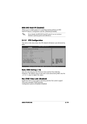
...Max CPUID Value Limit: [Disabled] Excute Disable Function [Disabled] Hyper Threading Technology [Disabled] Ratio CMOS Setting [ 16] Sets the ratio between the CPU Core Clock and the Front Side Bus frequency. BIOS EHCI Hand-Off [Enabled] Allows you are running a Windows® operating system with extended CPUID... functions. Use the or keys to boot legacy operating systems that cannot support CPUs with USB device. 2.4.3 CPU Configuration The items in this item is auto-detected by BIOS. Configuration options: [Disabled] [Enabled] ASUS P5VDC-MX 2-19
...Max CPUID Value Limit: [Disabled] Excute Disable Function [Disabled] Hyper Threading Technology [Disabled] Ratio CMOS Setting [ 16] Sets the ratio between the CPU Core Clock and the Front Side Bus frequency. BIOS EHCI Hand-Off [Enabled] Allows you are running a Windows® operating system with extended CPUID... functions. Use the or keys to boot legacy operating systems that cannot support CPUs with USB device. 2.4.3 CPU Configuration The items in this item is auto-detected by BIOS. Configuration options: [Disabled] [Enabled] ASUS P5VDC-MX 2-19

Motherboard DIY Troubleshooting Guide
Page 75
...Fan Speed [xxxxRPM] or [N/A] The onboard hardware monitor automatically detects and displays the chassis fan speed in rotations per minute (RPM). ASUS P5VDC-MX 2-29 Select Ignored if you to enable or disable RTC to generate a wake event. Resume On RTC Alarm [Disabled] Allows you...Alarm Second appear with set to display the detected fan speed. Configuration options: [Disabled] [Enabled] 2.5.6 Hardware Monitor Hardware Monitor CPU Temperature MB Temperature CPU Fan Speed Chassis Fan Speed VCORE Voltage 3.3V Voltage 5V Voltage 12V Voltage Q-FAN Function [51ºC/122.5ºF] [41&#...
...Fan Speed [xxxxRPM] or [N/A] The onboard hardware monitor automatically detects and displays the chassis fan speed in rotations per minute (RPM). ASUS P5VDC-MX 2-29 Select Ignored if you to enable or disable RTC to generate a wake event. Resume On RTC Alarm [Disabled] Allows you...Alarm Second appear with set to display the detected fan speed. Configuration options: [Disabled] [Enabled] 2.5.6 Hardware Monitor Hardware Monitor CPU Temperature MB Temperature CPU Fan Speed Chassis Fan Speed VCORE Voltage 3.3V Voltage 5V Voltage 12V Voltage Q-FAN Function [51ºC/122.5ºF] [41&#...

Motherboard DIY Troubleshooting Guide
Page 76
...voltage regulators. Configuration options: Configuration options: [Auto] [90%] [80%]~[20%] 2.6 Boot menu The Boot menu items allow you enable th CPU Q-Fan Function. Boot Settings Boot Device Priority Boot Settings Configuration Security 2.6.1 Boot Device Priority Boot Device Priority 1st Boot Device 2nd Boot Device ...3rd Boot Device [1st FLOPPY DRIVE] [PM-ST330620A] [PS-ASUS CD-S360] 1st ~ xxth Boot Device [1st Floppy Drive] These items specify the boot device priority sequence from the available devices. The...
...voltage regulators. Configuration options: Configuration options: [Auto] [90%] [80%]~[20%] 2.6 Boot menu The Boot menu items allow you enable th CPU Q-Fan Function. Boot Settings Boot Device Priority Boot Settings Configuration Security 2.6.1 Boot Device Priority Boot Device Priority 1st Boot Device 2nd Boot Device ...3rd Boot Device [1st FLOPPY DRIVE] [PM-ST330620A] [PS-ASUS CD-S360] 1st ~ xxth Boot Device [1st Floppy Drive] These items specify the boot device priority sequence from the available devices. The...


