Motherboard DIY Troubleshooting Guide
Page 5
...2.5.2 Repost Video on S3 Resume [No 2-27 2.5.3 ACPI 2.0 Support [No 2-27 2.5.4 ACPI APIC Support [Enabled 2-27 2.5.5 APM Configuration 2-28 2.5.6 Hardware Monitor 2-29 2.6 Boot menu 2-30 2.6.1 Boot Device Priority 2-30 2.6.2 Boot Settings Configuration 2-31 2.6.3 Security 2-32 2.7 Exit menu 2-34 Chapter 3: Software support 3.1 Installing an operating system 3-2 3.2 Support CD information 3-2 3.2.1 Running the support CD 3-2 3.2.2 Drivers menu 3-3 3.2.3 Utilities menu 3-4 3.2.4 Make Disk menu 3-5 3.2.5 Manuals menu 3-5 3.2.6 ASUS Contact information 3-6 3.3 RAID configurations...
...2.5.2 Repost Video on S3 Resume [No 2-27 2.5.3 ACPI 2.0 Support [No 2-27 2.5.4 ACPI APIC Support [Enabled 2-27 2.5.5 APM Configuration 2-28 2.5.6 Hardware Monitor 2-29 2.6 Boot menu 2-30 2.6.1 Boot Device Priority 2-30 2.6.2 Boot Settings Configuration 2-31 2.6.3 Security 2-32 2.7 Exit menu 2-34 Chapter 3: Software support 3.1 Installing an operating system 3-2 3.2 Support CD information 3-2 3.2.1 Running the support CD 3-2 3.2.2 Drivers menu 3-3 3.2.3 Utilities menu 3-4 3.2.4 Make Disk menu 3-5 3.2.5 Manuals menu 3-5 3.2.6 ASUS Contact information 3-6 3.3 RAID configurations...
Motherboard DIY Troubleshooting Guide
Page 15
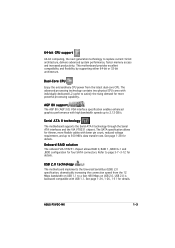
The advanced processing technology contains two physical CPU cores with USB 1.1. Onboard RAID solution The onboard VIA VT8251 chipset allows RAID 0, RAID 1, RAID 0+1 and JBOD configuration for details. ASUS P5VDC-MX 1-3 See page 1-28 for four SATA connectors. This motherboard provides excellent compatibility and flexibility by supporting either 64-bit or 32-bit architecture. AGP 8X support The AGP 8X (AGP 3.0) VGA interface specification enables enhanced graphics performance with lower pin count, reduced voltage requirement, and up to 2.12 GB...
The advanced processing technology contains two physical CPU cores with USB 1.1. Onboard RAID solution The onboard VIA VT8251 chipset allows RAID 0, RAID 1, RAID 0+1 and JBOD configuration for details. ASUS P5VDC-MX 1-3 See page 1-28 for four SATA connectors. This motherboard provides excellent compatibility and flexibility by supporting either 64-bit or 32-bit architecture. AGP 8X support The AGP 8X (AGP 3.0) VGA interface specification enables enhanced graphics performance with lower pin count, reduced voltage requirement, and up to 2.12 GB...

Motherboard DIY Troubleshooting Guide
Page 16
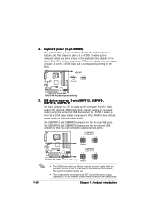
ASUS EZ Flash BIOS With the ASUS EZ Flash, you to use a DOS-based utility or boot from the support CD in case when the BIOS codes and data are corrupted. AUDIO CODEC The Realtek ALC653 is an AC"97 CODEC that allows 6-channel audio playback. ASUS Q-Fan technology The ASUS Q-Fan technology smartly adjusts the CPU fan speed according to the system loading to buy a replacement ROM chip. See details on page 2-6. No need to ensure quiet, cool, and...
ASUS EZ Flash BIOS With the ASUS EZ Flash, you to use a DOS-based utility or boot from the support CD in case when the BIOS codes and data are corrupted. AUDIO CODEC The Realtek ALC653 is an AC"97 CODEC that allows 6-channel audio playback. ASUS Q-Fan technology The ASUS Q-Fan technology smartly adjusts the CPU fan speed according to the system loading to buy a replacement ROM chip. See details on page 2-6. No need to ensure quiet, cool, and...
Motherboard DIY Troubleshooting Guide
Page 32
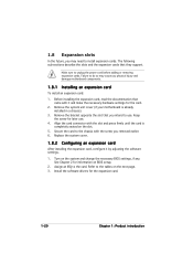
... need to unplug the power cord before adding or removing expansion cards. Turn on the slot. 5. Align the card connector with it by adjusting the software settings. 1. Install the software drivers for later use . Before installing the expansion card, read the documentation that came with the slot and press firmly until the card is already installed in a chassis). 3. Replace the system cover. 1.8.2 Configuring an expansion card After installing the expansion card, configure it and make...
... need to unplug the power cord before adding or removing expansion cards. Turn on the slot. 5. Align the card connector with it by adjusting the software settings. 1. Install the software drivers for later use . Before installing the expansion card, read the documentation that came with the slot and press firmly until the card is already installed in a chassis). 3. Replace the system cover. 1.8.2 Configuring an expansion card After installing the expansion card, configure it and make...
Motherboard DIY Troubleshooting Guide
Page 36
... power mode) using the connected USB devices. The USBPWR56 and USBPWR78 jumpers are for the internal USB connectors that can provide 500mA on the +5VSB lead for each USB port; USBPW12 USBPW34 12 23 P5VDC-MX +5V (Default) +5VSB USBPW56 ® USBPW78 12 23 1-24 P5VDC-MX USB device wake-up +5V (Default) +5VSB • The USB device wake-up from S1 sleep mode (CPU stopped, DRAM refreshed, system running in the BIOS. KBPWR 12 23 +5V (Default) +5VSB P5VDC-MX ® P5VDC-MX Keyboard power setting...
... power mode) using the connected USB devices. The USBPWR56 and USBPWR78 jumpers are for the internal USB connectors that can provide 500mA on the +5VSB lead for each USB port; USBPW12 USBPW34 12 23 P5VDC-MX +5V (Default) +5VSB USBPW56 ® USBPW78 12 23 1-24 P5VDC-MX USB device wake-up +5V (Default) +5VSB • The USB device wake-up from S1 sleep mode (CPU stopped, DRAM refreshed, system running in the BIOS. KBPWR 12 23 +5V (Default) +5VSB P5VDC-MX ® P5VDC-MX Keyboard power setting...

Motherboard DIY Troubleshooting Guide
Page 37
... p o r t ( l i m e ) . This port connects a tape, CD, DVD player, or other devices. 3 . In 4-channel and 6-channel configuration, the function of this port becomes Rear Speaker Out. 5 . ASUS P5VDC-MX 1-25 This port allows connection to a Local Area Network (LAN) through a network hub. M i c r o p h o n e p o r t ( p i n k ) . 1.10 Connectors 1.10.1 Rear panel connectors 1 2 3 4 5 6 11 10 9 87 1 . LAN port LED indications ACT/LINK LED Status OFF ORANGE BLINKING Description No link 100 Linked Data activity SPEED LED Status OFF GREEN BLINKING Description No link...
... p o r t ( l i m e ) . This port connects a tape, CD, DVD player, or other devices. 3 . In 4-channel and 6-channel configuration, the function of this port becomes Rear Speaker Out. 5 . ASUS P5VDC-MX 1-25 This port allows connection to a Local Area Network (LAN) through a network hub. M i c r o p h o n e p o r t ( p i n k ) . 1.10 Connectors 1.10.1 Rear panel connectors 1 2 3 4 5 6 11 10 9 87 1 . LAN port LED indications ACT/LINK LED Status OFF ORANGE BLINKING Description No link 100 Linked Data activity SPEED LED Status OFF GREEN BLINKING Description No link...
Motherboard DIY Troubleshooting Guide
Page 45
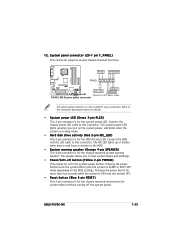
... IDE LED lights up when you to hear system beeps and warnings. • Power/Soft-off the system power. Pressing the power switch for more than four seconds while the system is ON turns the system OFF. • Reset button (Blue 2-pin RESET) This 2-pin connector is for the chassis-mounted reset button for system reboot without turning off button (Yellow 2-pin PWRSW) This connector is for easy connection. Connect the HDD Activity LED cable to this connector. ASUS P5VDC-MX...
... IDE LED lights up when you to hear system beeps and warnings. • Power/Soft-off the system power. Pressing the power switch for more than four seconds while the system is ON turns the system OFF. • Reset button (Blue 2-pin RESET) This 2-pin connector is for the chassis-mounted reset button for system reboot without turning off button (Yellow 2-pin PWRSW) This connector is for easy connection. Connect the HDD Activity LED cable to this connector. ASUS P5VDC-MX...

Motherboard DIY Troubleshooting Guide
Page 49
... or reset the system while updating the BIOS to the floppy disk drive. A "P5VDCMX.ROM not found !" Make sure that contains the BIOS file to prevent system boot failure! • A "Floppy not found !" ASUS P5VDC-MX 2-3 e. To use EZ Flash feature on motherboards with onboard VGA, you rename the BIOS file to display the following. Reading file "P5VDCMX.ROM". The EZ Flash utility is built-in the BIOS chip so it is accessible by pressing + during POST to P5VDCMX.ROM. R O M. 2. EZFlash starting BIOS update Checking...
... or reset the system while updating the BIOS to the floppy disk drive. A "P5VDCMX.ROM not found !" Make sure that contains the BIOS file to prevent system boot failure! • A "Floppy not found !" ASUS P5VDC-MX 2-3 e. To use EZ Flash feature on motherboards with onboard VGA, you rename the BIOS file to display the following. Reading file "P5VDCMX.ROM". The EZ Flash utility is built-in the BIOS chip so it is accessible by pressing + during POST to P5VDCMX.ROM. R O M. 2. EZFlash starting BIOS update Checking...

Motherboard DIY Troubleshooting Guide
Page 54
... you update the BIOS using this utility. 2-8 Chapter 2: BIOS setup Place the support CD in the support CD that allows you to manage, save, and update the motherboard BIOS in Windows® environment. ASUS Update requires an Internet connection either through a network or an Internet Service Provider (ISP). Click the U t i l i t i e s tab, then click I n s t a l l A S U S U p d a t e V X . See page 3-4 for the U t i l i t i e s screen menu. 3. 2.1.5 ASUS Update utility The ASUS Update is a utility that comes with the motherboard package. Installing ASUS Update To install ASUS Update...
... you update the BIOS using this utility. 2-8 Chapter 2: BIOS setup Place the support CD in the support CD that allows you to manage, save, and update the motherboard BIOS in Windows® environment. ASUS Update requires an Internet connection either through a network or an Internet Service Provider (ISP). Click the U t i l i t i e s tab, then click I n s t a l l A S U S U p d a t e V X . See page 3-4 for the U t i l i t i e s screen menu. 3. 2.1.5 ASUS Update utility The ASUS Update is a utility that comes with the motherboard package. Installing ASUS Update To install ASUS Update...
Motherboard DIY Troubleshooting Guide
Page 59
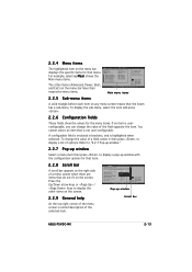
... the menu bar displays the specific items for the menu items. If an item is a brief description of the field opposite the item. Change Option F1 General Help F10 Save and Exit ESC Exit Pop-up window with the configuration options for that menu. Configure DRAM Timing by SPD Memory Acceleration Mode DRAM Idle Timer DRAm Refresh Rate [Enabled] [Auto] [Auto] [Auto] Graphic Adapter Priority Graphics Aperture Size Spread Spectrum [AGP/PCI] [ 64 MB] [Enabled...
... the menu bar displays the specific items for the menu items. If an item is a brief description of the field opposite the item. Change Option F1 General Help F10 Save and Exit ESC Exit Pop-up window with the configuration options for that menu. Configure DRAM Timing by SPD Memory Acceleration Mode DRAM Idle Timer DRAm Refresh Rate [Enabled] [Auto] [Auto] [Auto] Graphic Adapter Priority Graphics Aperture Size Spread Spectrum [AGP/PCI] [ 64 MB] [Enabled...
Motherboard DIY Troubleshooting Guide
Page 61
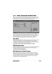
... values are specifically configuring a CD-ROM drive. Select ARMD (ATAPI Removable Media Device) if your device is a separate sub-menu for each IDE device. When set to [Disabled], the data transfer from and to display the IDE device information. Type [Auto] LBA/Large Mode [Auto] Block(Multi-sector Transfer)M [Auto] PIO Mode [Auto] DMA Mode [Auto] Smart Monitoring [Auto] 32Bit Data Transfer [Enabled] Select the type of device connected to Auto allows automatic selection of the appropriate IDE device type. Configuration options: [Disabled] [Auto] ASUS P5VDC-MX 2-15...
... values are specifically configuring a CD-ROM drive. Select ARMD (ATAPI Removable Media Device) if your device is a separate sub-menu for each IDE device. When set to [Disabled], the data transfer from and to display the IDE device information. Type [Auto] LBA/Large Mode [Auto] Block(Multi-sector Transfer)M [Auto] PIO Mode [Auto] DMA Mode [Auto] Smart Monitoring [Auto] 32Bit Data Transfer [Enabled] Select the type of device connected to Auto allows automatic selection of the appropriate IDE device type. Configuration options: [Disabled] [Auto] ASUS P5VDC-MX 2-15...

Motherboard DIY Troubleshooting Guide
Page 62
...Enables or disables 32-bit data transfer. AMIBIOS Version : 0110 Build Date : 10/05/05 Processor Type Speed Count : Genuine Intel(R) CPU 3.80GHz : 3914 MHz : 1 System Memory Usable Size : 192MB AMI BIOS Displays the auto-detected BIOS information Processor Displays the auto-detected CPU specification System Memory Displays the auto-detected system memory 2-16 Chapter 2: BIOS setup PIO Mode [Auto] Selects the PIO mode. Configuration options: [Auto] [SWDMA0] [SWDMA1] [SWDMA2] [MWDMA0] [MWDMA1] [MWDMA2] [UDMA0] [UDMA1] [UDMA2] [UDMA3] [UDMA04] [UDMA5] [UDMA6] SMART Monitoring [Auto...
...Enables or disables 32-bit data transfer. AMIBIOS Version : 0110 Build Date : 10/05/05 Processor Type Speed Count : Genuine Intel(R) CPU 3.80GHz : 3914 MHz : 1 System Memory Usable Size : 192MB AMI BIOS Displays the auto-detected BIOS information Processor Displays the auto-detected CPU specification System Memory Displays the auto-detected system memory 2-16 Chapter 2: BIOS setup PIO Mode [Auto] Selects the PIO mode. Configuration options: [Auto] [SWDMA0] [SWDMA1] [SWDMA2] [MWDMA0] [MWDMA1] [MWDMA2] [UDMA0] [UDMA1] [UDMA2] [UDMA3] [UDMA04] [UDMA5] [UDMA6] SMART Monitoring [Auto...

Motherboard DIY Troubleshooting Guide
Page 64
... or disable support for legacy USB devices. Select an item then press Enter to [Disabled] disables the USB 1.1 host controllers. Setting to display the configuration options. If detected, the USB controller legacy mode is disabled. If no USB device is detected, the item shows None. Configuration options: [Disabled] [Enabled] USB 2.0 Ports Enable [Enable] Allows you to configure the USB 2.0 controller in this menu allows you to enable or disable the USB 2.0 host controllers. Select Screen Select Item +- Advanced BIOS SETUP UTILITY USB Configuration Module Version...
... or disable support for legacy USB devices. Select an item then press Enter to [Disabled] disables the USB 1.1 host controllers. Setting to display the configuration options. If detected, the USB controller legacy mode is disabled. If no USB device is detected, the item shows None. Configuration options: [Disabled] [Enabled] USB 2.0 Ports Enable [Enable] Allows you to configure the USB 2.0 controller in this menu allows you to enable or disable the USB 2.0 host controllers. Select Screen Select Item +- Advanced BIOS SETUP UTILITY USB Configuration Module Version...

Motherboard DIY Troubleshooting Guide
Page 66
... Screen Select Item Enter Go to malfunction. Advanced BIOS SETUP UTILITY Advanced Chipset Settings WARNING: Setting wrong values in below sections may cause system to Subscreen F1 General Help F10 Save and Exit ESC Exit v02.58 (C)Copyright 1985-2004, American Megatrends, Inc. Configuration options: [Disabled] [Enabled] 2.4.4 Chipset The Chipset menu items allow you to display the sub-menu. Select an item then press to change the advanced chipset settings. Configuration options: [Disabled] [Enabled...
... Screen Select Item Enter Go to malfunction. Advanced BIOS SETUP UTILITY Advanced Chipset Settings WARNING: Setting wrong values in below sections may cause system to Subscreen F1 General Help F10 Save and Exit ESC Exit v02.58 (C)Copyright 1985-2004, American Megatrends, Inc. Configuration options: [Disabled] [Enabled] 2.4.4 Chipset The Chipset menu items allow you to display the sub-menu. Select an item then press to change the advanced chipset settings. Configuration options: [Disabled] [Enabled...

Motherboard DIY Troubleshooting Guide
Page 73
2.5 Power menu The Power menu items allow you to display the configuration options. Select an item then press to change the settings for system suspend. Main Advanced BIOS SETUP UTILITY Power Boot Exit Suspend Mode Repost Video on S3 Resume ACPI 2.0 Support ACPI APIC Support [Auto] [No] [No] [Enabled] APM Configuration Hardware Monitor Select the ACPI state used for the Advanced Configuration and Power Interface (ACPI) and the Advanced Power Management (APM). Configuration options: [S1 (POS) Only] [S3 Only] [Auto] 2.5.2 Repost Video on S3/STR resume...
2.5 Power menu The Power menu items allow you to display the configuration options. Select an item then press to change the settings for system suspend. Main Advanced BIOS SETUP UTILITY Power Boot Exit Suspend Mode Repost Video on S3 Resume ACPI 2.0 Support ACPI APIC Support [Auto] [No] [No] [Enabled] APM Configuration Hardware Monitor Select the ACPI state used for the Advanced Configuration and Power Interface (ACPI) and the Advanced Power Management (APM). Configuration options: [S1 (POS) Only] [S3 Only] [Auto] 2.5.2 Repost Video on S3/STR resume...

Motherboard DIY Troubleshooting Guide
Page 78
... Installed Change Supervisor Password Change User Password to change the system security settings. The Supervisor Password item on how to erase the RTC RAM. 2-32 Chapter 2: BIOS setup To clear the supervisor password, select the Change Supervisor Password then press . Confirm the password when prompted. 2.6.3 Security The Security menu items allow you to change password. Change Supervisor Password Select this item shows I n s t a l l e d. After you successfully set a Supervisor Password: 1. From the password box, type a password composed of the screen...
... Installed Change Supervisor Password Change User Password to change the system security settings. The Supervisor Password item on how to erase the RTC RAM. 2-32 Chapter 2: BIOS setup To clear the supervisor password, select the Change Supervisor Password then press . Confirm the password when prompted. 2.6.3 Security The Security menu items allow you to change password. Change Supervisor Password Select this item shows I n s t a l l e d. After you successfully set a Supervisor Password: 1. From the password box, type a password composed of the screen...

Motherboard DIY Troubleshooting Guide
Page 84
... optical drive. Use the setup procedures presented in your OS documentation for detailed information. • Make sure that you install Windows® 2000 Service Pack 4 or the Windows® XP Service Pack 1 or later versions before installing the drivers for better compatibility and system stability. 3.2 Support CD information The support CD that came with the motherboard package contains the drivers, software applications, and utilities that you can install to install...
... optical drive. Use the setup procedures presented in your OS documentation for detailed information. • Make sure that you install Windows® 2000 Service Pack 4 or the Windows® XP Service Pack 1 or later versions before installing the drivers for better compatibility and system stability. 3.2 Support CD information The support CD that came with the motherboard package contains the drivers, software applications, and utilities that you can install to install...
Motherboard DIY Troubleshooting Guide
Page 86
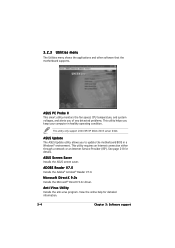
ASUS PC Probe II This smart utility monitors the fan speed, CPU temperature, and system voltages, and alerts you of any detected problems. This utility helps you to update the motherboard BIOS in healthy operating condition. ADOBE Reader V7.0 Installs the Adobe® Acrobat® Reader V7.0. Anti-Virus Utility Installs the anti-virus program. Microsoft DirectX 9.0c Installs the Microsoft® DirectX 9.0c driver. This utility only support 2000/XP/XP...
ASUS PC Probe II This smart utility monitors the fan speed, CPU temperature, and system voltages, and alerts you of any detected problems. This utility helps you to update the motherboard BIOS in healthy operating condition. ADOBE Reader V7.0 Installs the Adobe® Acrobat® Reader V7.0. Anti-Virus Utility Installs the anti-virus program. Microsoft DirectX 9.0c Installs the Microsoft® DirectX 9.0c driver. This utility only support 2000/XP/XP...
Motherboard DIY Troubleshooting Guide
Page 90
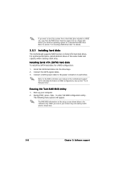
... a RAID driver disk" for details. 3.3.1 Installing hard disks The motherboard supports RAID function on Serial ATA hard disk drives. See section "3.2.4 Manuals menu". The following menu options will appear. Refer to the RAID controllers user manual in a RAID set, copy first the RAID driver from the support CD to a floppy disk before you install an operating system to enter VIA RAID configuration utility. Installing Serial ATA (SATA) hard disks To install the SATA hard disks for a RAID configuration: 1. During POST, press to a selected hard disk drive. Boot-up your screen may...
... a RAID driver disk" for details. 3.3.1 Installing hard disks The motherboard supports RAID function on Serial ATA hard disk drives. See section "3.2.4 Manuals menu". The following menu options will appear. Refer to the RAID controllers user manual in a RAID set, copy first the RAID driver from the support CD to a floppy disk before you install an operating system to enter VIA RAID configuration utility. Installing Serial ATA (SATA) hard disks To install the SATA hard disks for a RAID configuration: 1. During POST, press to a selected hard disk drive. Boot-up your screen may...

Motherboard DIY Troubleshooting Guide
Page 94
... succeeding screen information to complete the installation. 3-12 Chapter 3: Software support To install the RAID driver: 1. Place the motherboard support CD into the floppy disk drive. 3. Follow the succeeding screen instructions to complete process. 5. During the OS installation, the system prompts you to press the F6 key to floppy disk drive. 4. When the D r i v e r s menu appears, click M a k e V I A V T 8 2 5 1 3 2 / 6 4 b i t R A I D D r i v e r D i s k to create a VIA RAID driver disk Or Browse the contents of the support CD to locate the driver disk utility and...
... succeeding screen information to complete the installation. 3-12 Chapter 3: Software support To install the RAID driver: 1. Place the motherboard support CD into the floppy disk drive. 3. Follow the succeeding screen instructions to complete process. 5. During the OS installation, the system prompts you to press the F6 key to floppy disk drive. 4. When the D r i v e r s menu appears, click M a k e V I A V T 8 2 5 1 3 2 / 6 4 b i t R A I D D r i v e r D i s k to create a VIA RAID driver disk Or Browse the contents of the support CD to locate the driver disk utility and...


