Motherboard Installation Guide
Page 15
... items in the long line of the above items is damaged or missing, contact your motherboard package for buying an ASUS® P5RD1-V motherboard! 1.1 Welcome! Before you for the following items. Motherboard ASUS P5RD1-V motherboard I/O modules Serial port module (COM port) USB 2.0 (2 ports) and GAME (1 port) module Cables 2 x Serial ATA signal cables 1 x Serial ATA...
... items in the long line of the above items is damaged or missing, contact your motherboard package for buying an ASUS® P5RD1-V motherboard! 1.1 Welcome! Before you for the following items. Motherboard ASUS P5RD1-V motherboard I/O modules Serial port module (COM port) USB 2.0 (2 ports) and GAME (1 port) module Cables 2 x Serial ATA signal cables 1 x Serial ATA...

Motherboard Installation Guide
Page 17
... devices and allows higher clockspeeds by the ASIC (integrated in packets. The system fan rotations per minute (RPM) is fully-compliant with existing PCI specifications. ASUS P5RD1-V 1-3 See page 2-19 for four SATA connectors. Temperature, fan, and voltage monitoring The CPU temperature is the Realtek® ALC 861 8-channel audio CODEC. This...
... devices and allows higher clockspeeds by the ASIC (integrated in packets. The system fan rotations per minute (RPM) is fully-compliant with existing PCI specifications. ASUS P5RD1-V 1-3 See page 2-19 for four SATA connectors. Temperature, fan, and voltage monitoring The CPU temperature is the Realtek® ALC 861 8-channel audio CODEC. This...

Motherboard Installation Guide
Page 20
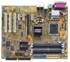
Chapter summary 2.1 Before you proceed 2-1 2.2 Motherboard overview 2-2 2.3 Central Processing Unit (CPU 2-6 2.4 System memory 2-13 2.5 Expansion slots 2-17 2.6 Jumpers 2-20 2.7 Connectors 2-23 ASUS P5RD1-V
Chapter summary 2.1 Before you proceed 2-1 2.2 Motherboard overview 2-2 2.3 Central Processing Unit (CPU 2-6 2.4 System memory 2-13 2.5 Expansion slots 2-17 2.6 Jumpers 2-20 2.7 Connectors 2-23 ASUS P5RD1-V

Motherboard Installation Guide
Page 21
... component, place it on a grounded antistatic pad or in the bag that the ATX power supply is switched off mode. P5RD1-V ® SB_PWR P5RD1-V Onboard LED ON Standby Power OFF Powered Off ASUS P5RD1-V 2-1 The illustration below shows the location of the following precautions before you install motherboard components or change any motherboard settings...
... component, place it on a grounded antistatic pad or in the bag that the ATX power supply is switched off mode. P5RD1-V ® SB_PWR P5RD1-V Onboard LED ON Standby Power OFF Powered Off ASUS P5RD1-V 2-1 The illustration below shows the location of the following precautions before you install motherboard components or change any motherboard settings...

Motherboard Installation Guide
Page 25
...) 15. Reset switch (Blue 2-pin RESET) Page 2-25 2-25 2-25 2-26 2-27 2-27 2-27 2-28 2-28 2-29 2-29 2-30 2-30 2-31 2-31 2-32 2-32 2-33 ASUS P5RD1-V 2-5 Primary IDE connector (40-1 pin PRI_IDE) 3. Chassis fan connector 1 (3-pin CHA_FAN1) 8. Power/Soft-off button(Yellow 2-pin PWR) -
...) 15. Reset switch (Blue 2-pin RESET) Page 2-25 2-25 2-25 2-26 2-27 2-27 2-27 2-28 2-28 2-29 2-29 2-30 2-30 2-31 2-31 2-32 2-32 2-33 ASUS P5RD1-V 2-5 Primary IDE connector (40-1 pin PRI_IDE) 3. Chassis fan connector 1 (3-pin CHA_FAN1) 8. Power/Soft-off button(Yellow 2-pin PWR) -

Motherboard Installation Guide
Page 27
..., making sure that the gold triangle is released from the load plate window to the left (B) until it to remove (B). Load plate 5. Gold triangle mark ASUS P5RD1-V A 2-7 To prevent damage to a 135º angle. 4. 2.
..., making sure that the gold triangle is released from the load plate window to the left (B) until it to remove (B). Load plate 5. Gold triangle mark ASUS P5RD1-V A 2-7 To prevent damage to a 135º angle. 4. 2.
Motherboard Installation Guide
Page 29
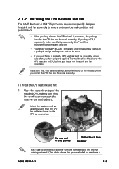
... install the CPU fan and heatsink assembly. Place the heatsink on top of the groove pointing outward. (The photo shows the groove shaded for emphasis.) ASUS P5RD1-V 2-9 Orient the heatsink and fan assembly such that you have properly applied Thermal Interface Material to ensure optimum thermal condition and performance. • When you...
... install the CPU fan and heatsink assembly. Place the heatsink on top of the groove pointing outward. (The photo shows the groove shaded for emphasis.) ASUS P5RD1-V 2-9 Orient the heatsink and fan assembly such that you have properly applied Thermal Interface Material to ensure optimum thermal condition and performance. • When you...

Motherboard Installation Guide
Page 31
Pull up two fasteners at a time in a diagonal sequence to disengage the heatsink B and fan assembly from the connector on the motherboard. 2. 2.3.3 Uninstalling the CPU heatsink and fan To uninstall the CPU heatsink and fan: 1. Disconnect the CPU fan cable from the A A motherboard. Rotate each fastener counterclockwise. 3. B A B B A ASUS P5RD1-V 2-11
Pull up two fasteners at a time in a diagonal sequence to disengage the heatsink B and fan assembly from the connector on the motherboard. 2. 2.3.3 Uninstalling the CPU heatsink and fan To uninstall the CPU heatsink and fan: 1. Disconnect the CPU fan cable from the A A motherboard. Rotate each fastener counterclockwise. 3. B A B B A ASUS P5RD1-V 2-11

Motherboard Installation Guide
Page 33
... DIMM pairs for each channel. • Always install DIMMs with four 184-pin Double Data Rate (DDR) Dual Inline Memory Modules (DIMM) sockets. ASUS P5RD1-V 2-13 For optimum compatibility, it is recommended that you installed four 1 GB DDR memory modules. DIMM_A1 DIMM_A2 DIMM_B1 DIMM_B2 80 Pins 104 Pins 2.4 System... memory 2.4.1 Overview The motherboard comes with the same CAS latency. Use any of the sockets: P5RD1-V ® P5RD1-V 184-pin DDR DIMM sockets 2.4.2 Memory configurations You may cause memory sizing error or system boot failure.
... DIMM pairs for each channel. • Always install DIMMs with four 184-pin Double Data Rate (DDR) Dual Inline Memory Modules (DIMM) sockets. ASUS P5RD1-V 2-13 For optimum compatibility, it is recommended that you installed four 1 GB DDR memory modules. DIMM_A1 DIMM_A2 DIMM_B1 DIMM_B2 80 Pins 104 Pins 2.4 System... memory 2.4.1 Overview The motherboard comes with the same CAS latency. Use any of the sockets: P5RD1-V ® P5RD1-V 184-pin DDR DIMM sockets 2.4.2 Memory configurations You may cause memory sizing error or system boot failure.

Motherboard Installation Guide
Page 35
...; • N/A SS GL3LC32G88TG-5A • • N/A SS WLCSP Package •• Ballistix SS N/A • CEON SS C2S56D30TP-5 • Aeneon SS AED83T500 • Legend: A - Double-sided ASUS P5RD1-V 2-15 support for 4 modules inserted into either slot, in a Single-channel memory configuration. Single-sided D S - supports one module inserted into either the blue slots or...
...; • N/A SS GL3LC32G88TG-5A • • N/A SS WLCSP Package •• Ballistix SS N/A • CEON SS C2S56D30TP-5 • Aeneon SS AED83T500 • Legend: A - Double-sided ASUS P5RD1-V 2-15 support for 4 modules inserted into either slot, in a Single-channel memory configuration. Single-sided D S - supports one module inserted into either the blue slots or...

Motherboard Installation Guide
Page 37
... following sub-sections describe the slots and the expansion cards that came with the screw you removed earlier. 6. Secure the card to install expansion cards. ASUS P5RD1-V 2-17 Before installing the expansion card, read the documentation that they support. See Chapter 4 for the card. 2. Refer to the card. Turn on the next...
... following sub-sections describe the slots and the expansion cards that came with the screw you removed earlier. 6. Secure the card to install expansion cards. ASUS P5RD1-V 2-17 Before installing the expansion card, read the documentation that they support. See Chapter 4 for the card. 2. Refer to the card. Turn on the next...

Motherboard Installation Guide
Page 39
... cards, SCSI cards and other cards that comply with the PCI Express specifications. The figure shows a graphics card installed on the PCI Express x1 slot. ASUS P5RD1-V 2-19
... cards, SCSI cards and other cards that comply with the PCI Express specifications. The figure shows a graphics card installed on the PCI Express x1 slot. ASUS P5RD1-V 2-19

Motherboard Installation Guide
Page 41
...Set to +5VSB to wake up feature requires a power supply that you can provide 500mA on the +5VSB lead for each USB port; ASUS P5RD1-V 2-21 The USBPWR12 and USBPWR34 jumpers are for the internal USB connectors that can connect to CPU, DRAM in slow refresh, power supply in... in reduced power mode). The USBPWR56 and USBPWR78 jumper is for the rear USB ports. 2 . USBPW12 USBPW34 3 2 2 1 P5RD1-V ® +5V +5VSB (Default) USBPW56 USBPW78 12 23 P5RD1-V USB device wake-up +5V (Default) +5VSB • The USB device wake-up the computer from S3 and S4 sleep modes...
...Set to +5VSB to wake up feature requires a power supply that you can provide 500mA on the +5VSB lead for each USB port; ASUS P5RD1-V 2-21 The USBPWR12 and USBPWR34 jumpers are for the internal USB connectors that can connect to CPU, DRAM in slow refresh, power supply in... in reduced power mode). The USBPWR56 and USBPWR78 jumper is for the rear USB ports. 2 . USBPW12 USBPW34 3 2 2 1 P5RD1-V ® +5V +5VSB (Default) USBPW56 USBPW78 12 23 P5RD1-V USB device wake-up +5V (Default) +5VSB • The USB device wake-up the computer from S3 and S4 sleep modes...

Motherboard Installation Guide
Page 43
... configuration, the function of the audio ports in an 8-channel audio configuration. 5 . Refer to the audio configuration table on a 4-channel, 6-channel, or 8-channel audio configuration. 4 . ASUS P5RD1-V 2-23 S i d e S p e a k e r O u t p o r t ( b l a c k ) . This port connects the tape, CD, DVD player, or other devices. 2 . C e n t e r / S u b w o o f e r p o r t ( y e l l o w o r a n g e ) . 2.7 Connectors 2.7.1 Rear panel connectors 1 2 3 45 6 13 12 11 10 9 87 1 . M i c r o p h o n e p o r t ( p i n k ) . This port connects...
... configuration, the function of the audio ports in an 8-channel audio configuration. 5 . Refer to the audio configuration table on a 4-channel, 6-channel, or 8-channel audio configuration. 4 . ASUS P5RD1-V 2-23 S i d e S p e a k e r O u t p o r t ( b l a c k ) . This port connects the tape, CD, DVD player, or other devices. 2 . C e n t e r / S u b w o o f e r p o r t ( y e l l o w o r a n g e ) . 2.7 Connectors 2.7.1 Rear panel connectors 1 2 3 45 6 13 12 11 10 9 87 1 . M i c r o p h o n e p o r t ( p i n k ) . This port connects...

Motherboard Installation Guide
Page 45
...the provided floppy disk drive (FDD) signal cable. Refer to prevent incorrect cable connection when using an FDD cable with a covered Pin 5. P5RD1-V ® P5RD1-V Floppy disk drive connector 2 . The Ultra DMA 133/100/66 signal cable has three connectors: a blue connector for the primary IDE ...: Orient the red markings on the IDE ribbon cable to match the covered hole on the Ultra DMA cable connector. PRI_IDE P5RD1-V ® P5RD1-V IDE connectors ASUS P5RD1-V NOTE: Orient the red markings (usually zigzag) on the floppy ribbon cable to the signal connector at the back of the...
...the provided floppy disk drive (FDD) signal cable. Refer to prevent incorrect cable connection when using an FDD cable with a covered Pin 5. P5RD1-V ® P5RD1-V Floppy disk drive connector 2 . The Ultra DMA 133/100/66 signal cable has three connectors: a blue connector for the primary IDE ...: Orient the red markings on the IDE ribbon cable to match the covered hole on the Ultra DMA cable connector. PRI_IDE P5RD1-V ® P5RD1-V IDE connectors ASUS P5RD1-V NOTE: Orient the red markings (usually zigzag) on the floppy ribbon cable to the signal connector at the back of the...

Motherboard Installation Guide
Page 47
Connect the fan cables to the fan connectors on the fan connectors! • The ASUS Q-Fan2 function is supported using the CPU Fan (CPU_FAN) and Chassis Fan 1 (CHA_FAN1) connectors only. DO NOT place jumper caps on the motherboard, making sure ...; CPU_FAN CHA_FAN1 PWR_FAN CPU_FAN CPU FAN PWM CPU FAN IN CPU FAN PWR CHA_FAN1 Rotation +12V GND PWR_FAN GND +12V Rotation P5RD1-V Fan connectors ASUS P5RD1-V 2-27 CPU, Chassis, and Power fan connectors (4-pin CPU_FAN, 3-pin PWR_FAN, 3-pin CHA_FAN1) The fan connectors support cooling fans of 350mA~2000mA (24 W max.) or a ...
Connect the fan cables to the fan connectors on the fan connectors! • The ASUS Q-Fan2 function is supported using the CPU Fan (CPU_FAN) and Chassis Fan 1 (CHA_FAN1) connectors only. DO NOT place jumper caps on the motherboard, making sure ...; CPU_FAN CHA_FAN1 PWR_FAN CPU_FAN CPU FAN PWM CPU FAN IN CPU FAN PWR CHA_FAN1 Rotation +12V GND PWR_FAN GND +12V Rotation P5RD1-V Fan connectors ASUS P5RD1-V 2-27 CPU, Chassis, and Power fan connectors (4-pin CPU_FAN, 3-pin PWR_FAN, 3-pin CHA_FAN1) The fan connectors support cooling fans of 350mA~2000mA (24 W max.) or a ...

Motherboard Installation Guide
Page 49
... Volts +5V Standby Power OK Ground +5 Volts Ground +5 Volts Ground +3 Volts +3 Volts Ground +5 Volts +5 Volts +5 Volts -5 Volts Ground Ground Ground PSON# Ground -12 Volts +3 Volts ASUS P5RD1-V 2-29 ATX power connectors (24-pin EATXPWR, 4-pin ATX12V) These connectors are designed to connect the 4-pin ATX +12 V power plug; The power supply plugs...
... Volts +5V Standby Power OK Ground +5 Volts Ground +5 Volts Ground +3 Volts +3 Volts Ground +5 Volts +5 Volts +5 Volts -5 Volts Ground Ground Ground PSON# Ground -12 Volts +3 Volts ASUS P5RD1-V 2-29 ATX power connectors (24-pin EATXPWR, 4-pin ATX12V) These connectors are designed to connect the 4-pin ATX +12 V power plug; The power supply plugs...

Motherboard Installation Guide
Page 51
... • The default setting of this connector when a chassis component is then generated as a chassis intrusion event. See page 4-26. ASUS P5RD1-V 2-31 The chassis intrusion sensor or switch sends a high-level signal to this connector is for a chassis-mounted intrusion detection sensor or... is legacy AC'97 audio, if you intend to use the chassis intrusion detection feature. CHASSIS +5VSB_MB Chassis Signal GND P5RD1-V ® (Default) P5RD1-V Chassis intrusion connector 11. 10. Connect one end of the chassis intrusion sensor or switch cable to Azalia. GND PRESENCE...
... • The default setting of this connector when a chassis component is then generated as a chassis intrusion event. See page 4-26. ASUS P5RD1-V 2-31 The chassis intrusion sensor or switch sends a high-level signal to this connector is for a chassis-mounted intrusion detection sensor or... is legacy AC'97 audio, if you intend to use the chassis intrusion detection feature. CHASSIS +5VSB_MB Chassis Signal GND P5RD1-V ® (Default) P5RD1-V Chassis intrusion connector 11. 10. Connect one end of the chassis intrusion sensor or switch cable to Azalia. GND PRESENCE...

Motherboard Installation Guide
Page 53
... • System power LED (Green 3-pin PLED) This 3-pin connector is for the system power LED. PLED SPEAKER PLED+ PLED+5V Ground Ground Speaker P5RD1-V ® PANEL IDE_LED+ IDE_LED- Connect the HDD Activity LED cable to the HDD. • System warning speaker (Orange 4-pin SPEAKER) This 4-pin ... panel connector RESET PWR The sytem panel connector is for easy connection. Connect the chassis power LED cable to this connector. ASUS P5RD1-V 2-33 14. Pressing the power switch for more than four seconds while the system is ON turns the system OFF. • Reset button...
... • System power LED (Green 3-pin PLED) This 3-pin connector is for the system power LED. PLED SPEAKER PLED+ PLED+5V Ground Ground Speaker P5RD1-V ® PANEL IDE_LED+ IDE_LED- Connect the HDD Activity LED cable to the HDD. • System warning speaker (Orange 4-pin SPEAKER) This 4-pin ... panel connector RESET PWR The sytem panel connector is for easy connection. Connect the chassis power LED cable to this connector. ASUS P5RD1-V 2-33 14. Pressing the power switch for more than four seconds while the system is ON turns the system OFF. • Reset button...

Motherboard Installation Guide
Page 56
Chapter summary 3.1 Starting up for the first time 3-1 3.2 Powering off the computer 3-2 ASUS P5RD1-V
Chapter summary 3.1 Starting up for the first time 3-1 3.2 Powering off the computer 3-2 ASUS P5RD1-V


