
User Guide
Page 1
P5QL-VM DO Motherboard
P5QL-VM DO Motherboard

User Guide
Page 2
... it, may not be reproduced, transmitted, transcribed, stored in a retrieval system, or translated into any means, except documentation kept by ASUS; ASUS PROVIDES THIS MANUAL "AS IS" WITHOUT WARRANTY OF ANY KIND, EITHER EXPRESS OR IMPLIED, INCLUDING BUT NOT LIMITED TO THE IMPLIED WARRANTIES ...OR CONDITIONS OF MERCHANTABILITY OR FITNESS FOR A PARTICULAR PURPOSE. ASUS ASSUMES NO RESPONSIBILITY OR LIABILITY FOR ANY ERRORS OR INACCURACIES THAT MAY APPEAR IN THIS MANUAL, INCLUDING THE PRODUCTS AND SOFTWARE DESCRIBED ...
... it, may not be reproduced, transmitted, transcribed, stored in a retrieval system, or translated into any means, except documentation kept by ASUS; ASUS PROVIDES THIS MANUAL "AS IS" WITHOUT WARRANTY OF ANY KIND, EITHER EXPRESS OR IMPLIED, INCLUDING BUT NOT LIMITED TO THE IMPLIED WARRANTIES ...OR CONDITIONS OF MERCHANTABILITY OR FITNESS FOR A PARTICULAR PURPOSE. ASUS ASSUMES NO RESPONSIBILITY OR LIABILITY FOR ANY ERRORS OR INACCURACIES THAT MAY APPEAR IN THIS MANUAL, INCLUDING THE PRODUCTS AND SOFTWARE DESCRIBED ...
User Guide
Page 3
Contents Notices...v Safety information vi About this guide vii P5QL-VM DO specifications summary viii Chapter 1: Product introduction 1.1 Before you proceed 1-1 1.2 Motherboard overview 1-2 1.2.1 Motherboard layout 1-2 1.2.2 Layout contents 1-2 1.3 Central Processing Unit (CPU 1-3 1.4 System memory 1-3 1.4.1 Overview 1-3 1.4.2 Memory configurations 1-4 ... 1-18 Chapter 2: BIOS information 2.1 Managing and updating your BIOS 2-1 2.1.1 ASUS Update utility 2-1 2.1.2 ASUS EZ Flash 2 utility 2-2 2.1.3 ASUS CrashFree BIOS 3 utility 2-3 2.2 BIOS setup program 2-4 2.3 Main menu 2-4 iii
Contents Notices...v Safety information vi About this guide vii P5QL-VM DO specifications summary viii Chapter 1: Product introduction 1.1 Before you proceed 1-1 1.2 Motherboard overview 1-2 1.2.1 Motherboard layout 1-2 1.2.2 Layout contents 1-2 1.3 Central Processing Unit (CPU 1-3 1.4 System memory 1-3 1.4.1 Overview 1-3 1.4.2 Memory configurations 1-4 ... 1-18 Chapter 2: BIOS information 2.1 Managing and updating your BIOS 2-1 2.1.1 ASUS Update utility 2-1 2.1.2 ASUS EZ Flash 2 utility 2-2 2.1.3 ASUS CrashFree BIOS 3 utility 2-3 2.2 BIOS setup program 2-4 2.3 Main menu 2-4 iii

User Guide
Page 5
... (Registration, Evaluation, Authorisation, and Restriction of Chemicals) regulatory framework, we published the chemical substances in our products at ASUS REACH website at http://green.asus.com/english/REACH.htm DO NOT throw the motherboard in the Radio Interference Regulations of the Canadian Department of Communications. This symbol of the crossed out wheeled bin...
... (Registration, Evaluation, Authorisation, and Restriction of Chemicals) regulatory framework, we published the chemical substances in our products at ASUS REACH website at http://green.asus.com/english/REACH.htm DO NOT throw the motherboard in the Radio Interference Regulations of the Canadian Department of Communications. This symbol of the crossed out wheeled bin...
User Guide
Page 6
... staples away from connectors, slots, sockets and circuitry. • Avoid dust, humidity, and temperature extremes. Operation safety • Before installing the motherboard and adding devices on a stable surface. • If you are using the product, ensure that your power supply is set to the correct ... is broken, do not try to fix it to a hazardous material collection point. • Never replace the battery with your retailer. This motherboard should only be used in environments with ambient temperatures between 5℃ (14℉) and 40℃ (104℉). • Place the ...
... staples away from connectors, slots, sockets and circuitry. • Avoid dust, humidity, and temperature extremes. Operation safety • Before installing the motherboard and adding devices on a stable surface. • If you are using the product, ensure that your power supply is set to the correct ... is broken, do not try to fix it to a hazardous material collection point. • Never replace the battery with your retailer. This motherboard should only be used in environments with ambient temperatures between 5℃ (14℉) and 40℃ (104℉). • Place the ...
User Guide
Page 7
...key. About this guide is organized This guide contains the following parts: • Chapter 1: Product introduction This chapter describes the features of the motherboard and the new technology it supports. • Chapter 2: BIOS information This chapter tells how to change system settings through the BIOS setup menus.... Information to prevent injury to yourself when trying to select. Typography Bold text Italics ++ Indicates a menu or an item to complete a task. ASUS websites The ASUS website provides updated information on ASUS hardware and software products. 2.
...key. About this guide is organized This guide contains the following parts: • Chapter 1: Product introduction This chapter describes the features of the motherboard and the new technology it supports. • Chapter 2: BIOS information This chapter tells how to change system settings through the BIOS setup menus.... Information to prevent injury to yourself when trying to select. Typography Bold text Italics ++ Indicates a menu or an item to complete a task. ASUS websites The ASUS website provides updated information on ASUS hardware and software products. 2.

User Guide
Page 8
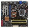
... panel I/O ports ** Refer to 10 USB 2.0/1.1 ports (4 ports at mid-board, 6 ports at the back panel) Intel® 82567LF Gigabit LAN Phy controller ASUS CrashFree BIOS 3 ASUS Q-Fan ASUS EZ Flash 2 ASUS MyLogo 2 1 x PS/2 Keyboard port 1 x PS/2 Mouse port 1 x COM port 1 x RJ45 port 1 x VGA port 1 x DVI port 1 x ME ...174; 32-bit operating system may only recognize less than 3GB is recommended if you are using a Windows 32-bit operating system. P5QL-VM DO specifications summary CPU Chipset Front Side Bus Memory LGA775 socket for Intel® Core™2 Quad / Core™2 Exreme / Core...
... panel I/O ports ** Refer to 10 USB 2.0/1.1 ports (4 ports at mid-board, 6 ports at the back panel) Intel® 82567LF Gigabit LAN Phy controller ASUS CrashFree BIOS 3 ASUS Q-Fan ASUS EZ Flash 2 ASUS MyLogo 2 1 x PS/2 Keyboard port 1 x PS/2 Mouse port 1 x COM port 1 x RJ45 port 1 x VGA port 1 x DVI port 1 x ME ...174; 32-bit operating system may only recognize less than 3GB is recommended if you are using a Windows 32-bit operating system. P5QL-VM DO specifications summary CPU Chipset Front Side Bus Memory LGA775 socket for Intel® Core™2 Quad / Core™2 Exreme / Core...

User Guide
Page 9
ix P5QL-VM DO specifications summary Internal I/O connectors BIOS Accessories Support DVD Form Factor 2 x USB ... connector 1 x CD audio-in connector 1 x Chassis intrusion connector 1 x TPM connector 1 x 24-pin EATX power connector 1 x 4-pin ATX 12V power connector 2 x 16Mb Flash ROM, AMI BIOS, PnP, DMI2.0, WfM2.0, SM BIOS 2.5, ACPI2.0a 2 x Serial ATA cables 1 x... I/O shield 1 x Support DVD 1 x User Manual Drivers ASUS Update ASUS PC Probe II Intel® IT Director Anti-Virus software (OEM version) uATX form factor: 9.6 in x 9.0 in (24...
ix P5QL-VM DO specifications summary Internal I/O connectors BIOS Accessories Support DVD Form Factor 2 x USB ... connector 1 x CD audio-in connector 1 x Chassis intrusion connector 1 x TPM connector 1 x 24-pin EATX power connector 1 x 4-pin ATX 12V power connector 2 x 16Mb Flash ROM, AMI BIOS, PnP, DMI2.0, WfM2.0, SM BIOS 2.5, ACPI2.0a 2 x Serial ATA cables 1 x... I/O shield 1 x Support DVD 1 x User Manual Drivers ASUS Update ASUS PC Probe II Intel® IT Director Anti-Virus software (OEM version) uATX form factor: 9.6 in x 9.0 in (24...

User Guide
Page 10
...below shows the location of the following precautions before you install motherboard components or change any motherboard settings. • Unplug the power cord from the wall socket before removing or plugging in soft-off the ATX power supply and detach its power cord. Chapter 1 Product .... 1.1 Before you install or remove any motherboard component. This is ON, in sleep mode, or in any component, switch off mode. SB_PWR P5QL-VM DO ON OFF Standby Power Powered Off P5QL-VM DO Onboard LED ASUS P5QL-VM DO 1-1 Onboard LED This motherboard comes with the component. • Before ...
...below shows the location of the following precautions before you install motherboard components or change any motherboard settings. • Unplug the power cord from the wall socket before removing or plugging in soft-off the ATX power supply and detach its power cord. Chapter 1 Product .... 1.1 Before you install or remove any motherboard component. This is ON, in sleep mode, or in any component, switch off mode. SB_PWR P5QL-VM DO ON OFF Standby Power Powered Off P5QL-VM DO Onboard LED ASUS P5QL-VM DO 1-1 Onboard LED This motherboard comes with the component. • Before ...

User Guide
Page 11
...; 82567LF PCI1 Intel® ICH10D Lithium Cell CMOS Power 6 CHASSIS CLRTC SB_PWR PCI2 P5QL-VM DO Super I/O 7 16Mb 16Mb SATA5 SATA3 SATA1 TPM VIA VT1705 CD PCI3 BIOS BIOS... 12 11 10 9 Place six screws into the chassis in connector (4-pin CD) 1-12 9. ATX power connectors (24-pin EATXPWR, 4-pin ATX12V) 1-14 12. Intel CPU socket 1-3 13. Onboard...connector (20-1 pin TPM) 1-17 17. 1.2 1.2.1 Motherboard overview Motherboard layout Ensure that you install the motherboard into the holes indicated by circles to secure the motherboard to the rear part of the chassis. 12 3 4...
...; 82567LF PCI1 Intel® ICH10D Lithium Cell CMOS Power 6 CHASSIS CLRTC SB_PWR PCI2 P5QL-VM DO Super I/O 7 16Mb 16Mb SATA5 SATA3 SATA1 TPM VIA VT1705 CD PCI3 BIOS BIOS... 12 11 10 9 Place six screws into the chassis in connector (4-pin CD) 1-12 9. ATX power connectors (24-pin EATXPWR, 4-pin ATX12V) 1-14 12. Intel CPU socket 1-3 13. Onboard...connector (20-1 pin TPM) 1-17 17. 1.2 1.2.1 Motherboard overview Motherboard layout Ensure that you install the motherboard into the holes indicated by circles to secure the motherboard to the rear part of the chassis. 12 3 4...

User Guide
Page 12
...of the DDR2 DIMM sockets: DIMM_A1 DIMM_A2 DIMM_B1 DIMM_B2 P5QL-VM DO P5QL-VM DO 240-pin DDR2 DIMM sockets ASUS P5QL-VM DO 1-3 Ensure that all power cables are unplugged before installing the CPU. • Upon purchase of the motherboard, ensure that the PnP cap is on the ... DDR2 DIMMs are not bent. 1.3 Central Processing Unit (CPU) This motherboard comes with four Double Data Rate 2 (DDR2) Dual Inline Memory Module (DIMM) sockets. ASUS will process Return Merchandise Authorization (RMA) requests only if the motherboard comes with the cap on a DDR DIMM socket. A DDR2 DIMM ...
...of the DDR2 DIMM sockets: DIMM_A1 DIMM_A2 DIMM_B1 DIMM_B2 P5QL-VM DO P5QL-VM DO 240-pin DDR2 DIMM sockets ASUS P5QL-VM DO 1-3 Ensure that all power cables are unplugged before installing the CPU. • Upon purchase of the motherboard, ensure that the PnP cap is on the ... DDR2 DIMMs are not bent. 1.3 Central Processing Unit (CPU) This motherboard comes with four Double Data Rate 2 (DDR2) Dual Inline Memory Module (DIMM) sockets. ASUS will process Return Merchandise Authorization (RMA) requests only if the motherboard comes with the cap on a DDR DIMM socket. A DDR2 DIMM ...

User Guide
Page 13
...8226; For dual-channel configuration, you install 4GB or more memory on the motherboard. • This motherboard does not support DIMMs made up of 256 megabits (Mb) chips or less. • This motherboard supports up to 16GB on W�in�d�o�w��s®... which is the standard way of 2) DS N/A 512MB SS Apacer 1024MB SS Apacer 1024MB DS Corsair 1024MB DS Corsair Chip No. P5Q-VM DO Motherboard Qualified Vendors List (QVL) DDR2-800MHz capability Vendor A-Data A-Data A-Data A-Data Apacer Apacer Corsair Corsair Part No. Install a maximum ...
...8226; For dual-channel configuration, you install 4GB or more memory on the motherboard. • This motherboard does not support DIMMs made up of 256 megabits (Mb) chips or less. • This motherboard supports up to 16GB on W�in�d�o�w��s®... which is the standard way of 2) DS N/A 512MB SS Apacer 1024MB SS Apacer 1024MB DS Corsair 1024MB DS Corsair Chip No. P5Q-VM DO Motherboard Qualified Vendors List (QVL) DDR2-800MHz capability Vendor A-Data A-Data A-Data A-Data Apacer Apacer Corsair Corsair Part No. Install a maximum ...

User Guide
Page 14
...; 6 • 4-4-4-12 2.0V • 5 1.8V 6 1.8V • 5-5-5-15 2.0V • 5 1.8V • 6 1.8V • 6 1.8V • 6-6-6-12 • 6-6-6-12 • 4-5-5-15 2.0V • 4-4-4-15 1.9 • - 2.1 V ASUS P5QL-VM DO 1-5 Size SS/ Chip DS Brand Chip No.
...; 6 • 4-4-4-12 2.0V • 5 1.8V 6 1.8V • 5-5-5-15 2.0V • 5 1.8V • 6 1.8V • 6 1.8V • 6-6-6-12 • 6-6-6-12 • 4-5-5-15 2.0V • 4-4-4-15 1.9 • - 2.1 V ASUS P5QL-VM DO 1-5 Size SS/ Chip DS Brand Chip No.

User Guide
Page 16
Single-sided / DS - Visit the ASUS website at www.asus.com for the latest QVL. sided DIMM support: • A*: Supports one module inserted into any slot as Single-channel memory configuration. • B*: Supports one pair ... Transcend JM667QLJ-1G 1024MB Transcend JM667QLU-2G 2048MB Twinmos 8D-A3JK5MPETP 512MB SS/ Chip DS Brand Chip No. Double - DDR2-667MHz capability Vendor Part No. ASUS P5QL-VM DO 1-7
Single-sided / DS - Visit the ASUS website at www.asus.com for the latest QVL. sided DIMM support: • A*: Supports one module inserted into any slot as Single-channel memory configuration. • B*: Supports one pair ... Transcend JM667QLJ-1G 1024MB Transcend JM667QLU-2G 2048MB Twinmos 8D-A3JK5MPETP 512MB SS/ Chip DS Brand Chip No. Double - DDR2-667MHz capability Vendor Part No. ASUS P5QL-VM DO 1-7

User Guide
Page 17
...sub-sections describe the slots and the expansion cards that you physical injury and damage motherboard components. 1.5.1 Installing an expansion card To install an expansion card: 1. Remove the chassis cover (if your motherboard is completely seated on shared slots, ensure that the drivers support "Share IRQ"...as LAN cards, SCSI cards, USB cards, and other cards that comply with the PCI specifications. 1.5.4 PCI Express x16 slot This motherboard supports PCI Express x16 graphics cards that comply with it by adjusting the software settings. 1. Before installing the expansion card, read the...
...sub-sections describe the slots and the expansion cards that you physical injury and damage motherboard components. 1.5.1 Installing an expansion card To install an expansion card: 1. Remove the chassis cover (if your motherboard is completely seated on shared slots, ensure that the drivers support "Share IRQ"...as LAN cards, SCSI cards, USB cards, and other cards that comply with the PCI specifications. 1.5.4 PCI Express x16 slot This motherboard supports PCI Express x16 graphics cards that comply with it by adjusting the software settings. 1. Before installing the expansion card, read the...

User Guide
Page 18
... Keyboard power (3-pin KBPWR) This jumper allows you to clear the CMOS RTC RAM data. KBPWR 12 23 +5V +5VSB (Default) P5QL-VM DO P5QL-VM DO Keyboard Power Setting ASUS P5QL-VM DO 1-9 After clearing the CMOS, reinstall the battery. • You do not help, remove the onboard battery and move the cap ...the system hangs due to enable or disable the keyboard wake-up the computer by erasing the CMOS RTC RAM data. This feature requires an ATX power supply that can clear the CMOS memory of date, time, and system setup parameters by pressing a key on pins 2-3 for about 5-...
... Keyboard power (3-pin KBPWR) This jumper allows you to clear the CMOS RTC RAM data. KBPWR 12 23 +5V +5VSB (Default) P5QL-VM DO P5QL-VM DO Keyboard Power Setting ASUS P5QL-VM DO 1-9 After clearing the CMOS, reinstall the battery. • You do not help, remove the onboard battery and move the cap ...the system hangs due to enable or disable the keyboard wake-up the computer by erasing the CMOS RTC RAM data. This feature requires an ATX power supply that can clear the CMOS memory of date, time, and system setup parameters by pressing a key on pins 2-3 for about 5-...

User Guide
Page 19
... sleep mode. 1.7 1.7.1 1 Connectors Rear panel ports 2 3 45 12 11 10 9 8 76 1. Video Graphics Adapter (VGA) port. PS/2 Mouse port. USBPW7-10 12 23 P5QL-VM DO +5V +5VSB (Default) P5QL-VM DO USB Device Wake Up • The USB device wake-up the computer from S3 and S4 sleep modes (no power to wake...
... sleep mode. 1.7 1.7.1 1 Connectors Rear panel ports 2 3 45 12 11 10 9 8 76 1. Video Graphics Adapter (VGA) port. PS/2 Mouse port. USBPW7-10 12 23 P5QL-VM DO +5V +5VSB (Default) P5QL-VM DO USB Device Wake Up • The USB device wake-up the computer from S3 and S4 sleep modes (no power to wake...

User Guide
Page 20
... 2.0 ports 1 and 2. These two 4-pin Universal Serial Bus (USB) ports connect to a microphone. DVI port. COM port. This port connects to USB 2.0/1.1 devices. 9. ME Switch. ASUS P5QL-VM DO 1-11 Line Out port (lime). Refer to the audio configuration table below for a PS/2 keyboard. Disable Intel® ME function before updating BIOS. 8. USB...
... 2.0 ports 1 and 2. These two 4-pin Universal Serial Bus (USB) ports connect to a microphone. DVI port. COM port. This port connects to USB 2.0/1.1 devices. 9. ME Switch. ASUS P5QL-VM DO 1-11 Line Out port (lime). Refer to the audio configuration table below for a PS/2 keyboard. Disable Intel® ME function before updating BIOS. 8. USB...

User Guide
Page 21
...Serial ATA 3Gb/s is backward compatible with 133MB/s (Ultra DMA133). CD Left Audio Channel GND GND Right Audio Channel P5QL-VM DO P5QL-VM DO Internal audio connector 1-12 Chapter 1: Product introduction SATA5 SATA3 SATA1 GND RSATA_RXN5 RSATA_RXP5 GND RSATA_TXN5 RSATA_TXP5 GND GND ...GND RSATA_RXN6 RSATA_RXP6 GND RSATA_TXN6 RSATA_TXP6 GND GND RSATA_RXN4 RSATA_RXP4 GND RSATA_TXN4 RSATA_TXP4 GND GND RSATA_RXN2 RSATA_RXP2 GND RSATA_TXN2 RSATA_TXP2 GND P5QL-VM DO P5QL-VM DO SATA connectors (ICH10D®) Install the Windows® XP Service Pack 2 or later version before using Serial ...
...Serial ATA 3Gb/s is backward compatible with 133MB/s (Ultra DMA133). CD Left Audio Channel GND GND Right Audio Channel P5QL-VM DO P5QL-VM DO Internal audio connector 1-12 Chapter 1: Product introduction SATA5 SATA3 SATA1 GND RSATA_RXN5 RSATA_RXP5 GND RSATA_TXN5 RSATA_TXP5 GND GND ...GND RSATA_RXN6 RSATA_RXP6 GND RSATA_TXN6 RSATA_TXP6 GND GND RSATA_RXN4 RSATA_RXP4 GND RSATA_TXN4 RSATA_TXP4 GND GND RSATA_RXN2 RSATA_RXP2 GND RSATA_TXN2 RSATA_TXP2 GND P5QL-VM DO P5QL-VM DO SATA connectors (ICH10D®) Install the Windows® XP Service Pack 2 or later version before using Serial ...

User Guide
Page 22
...fan connectors. Connect the fan cables to the fan connectors on the fan connectors. They are for USB 2.0 ports. Doing so will damage the motherboard! ASUS P5QL-VM DO 1-13 Connect the USB module cable to any of the system chassis. CPU, Chassis, and Power fan connectors (4-pin CPU_FAN, 3-pin ... jumper caps on the motherboard, making sure that supports up to a slot opening at +12V. CPU_FAN CPU FAN PWM CPU FAN IN CPU FAN PWR GND P5QL-VM DO CHA_FAN Rotation +12V GND P5QL-VM DO fan connectors PWR_FAN GND +12V Rotation Only the CPU fan supports the ASUS Q-FAN feature. 3. ...
...fan connectors. Connect the fan cables to the fan connectors on the fan connectors. They are for USB 2.0 ports. Doing so will damage the motherboard! ASUS P5QL-VM DO 1-13 Connect the USB module cable to any of the system chassis. CPU, Chassis, and Power fan connectors (4-pin CPU_FAN, 3-pin ... jumper caps on the motherboard, making sure that supports up to a slot opening at +12V. CPU_FAN CPU FAN PWM CPU FAN IN CPU FAN PWR GND P5QL-VM DO CHA_FAN Rotation +12V GND P5QL-VM DO fan connectors PWR_FAN GND +12V Rotation Only the CPU fan supports the ASUS Q-FAN feature. 3. ...