
User Manual
Page 1
P5Q WS Motherboard
P5Q WS Motherboard

User Manual
Page 3
Contents Contents...iii Notices...vii Safety information viii About this guide ix P5Q WS specifications summary xi Chapter 1: Product introduction 1.1 Welcome 1-1 1.2 Package contents 1-1 1.3 Special features 1-2 1.3.1 Product highlights 1-2 1.3.2 ASUS unique features 1-4 1.3.3 ASUS Intelligent Performance & Overclocking features.. 1-7 Chapter 2: Hardware information 2.1 Before you proceed 2-1 Onboard LED 2-1 2.2 Motherboard overview 2-2 2.2.1 Motherboard layout 2-2 2.2.2 Layout contents 2-3 2.2.3 Placement direction 2-4 2.2.4 Screw holes 2-4 2.3 Central Processing Unit (CPU...
Contents Contents...iii Notices...vii Safety information viii About this guide ix P5Q WS specifications summary xi Chapter 1: Product introduction 1.1 Welcome 1-1 1.2 Package contents 1-1 1.3 Special features 1-2 1.3.1 Product highlights 1-2 1.3.2 ASUS unique features 1-4 1.3.3 ASUS Intelligent Performance & Overclocking features.. 1-7 Chapter 2: Hardware information 2.1 Before you proceed 2-1 Onboard LED 2-1 2.2 Motherboard overview 2-2 2.2.1 Motherboard layout 2-2 2.2.2 Layout contents 2-3 2.2.3 Placement direction 2-4 2.2.4 Screw holes 2-4 2.3 Central Processing Unit (CPU...
User Manual
Page 17
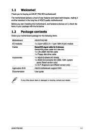
... features and latest technologies, making it , check the items in the long line of the above items is damaged or missing, contact your motherboard package for the following items. Motherboard ASUS P5Q WS I/O modules 1 x 2-port USB 2.0 + 1-port 1394 (4-pin) module Cables S�e�r�ia�l �AT�A��si�g�na...
... features and latest technologies, making it , check the items in the long line of the above items is damaged or missing, contact your motherboard package for the following items. Motherboard ASUS P5Q WS I/O modules 1 x 2-port USB 2.0 + 1-port 1394 (4-pin) module Cables S�e�r�ia�l �AT�A��si�g�na...

User Manual
Page 19
... 10 functions, and the Marvell® controller provides another two external Serial ATA connectors for RAID 0 and 1 functions, making this motherboard an ideal solution to enhance hard disk performance and data back up protection without the cost of data from WAN to LAN without any...for audio/video appliances such as a network gateway for details. See pages 2-22 and 2-28 for managing traffic between two separate networks. ASUS P5Q WS 1-3 Dual Gigabit LAN solution The integrated dual Gigabit LAN design allows a PC to serve as digital television, digital video camcorders, storage ...
... 10 functions, and the Marvell® controller provides another two external Serial ATA connectors for RAID 0 and 1 functions, making this motherboard an ideal solution to enhance hard disk performance and data back up protection without the cost of data from WAN to LAN without any...for audio/video appliances such as a network gateway for details. See pages 2-22 and 2-28 for managing traffic between two separate networks. ASUS P5Q WS 1-3 Dual Gigabit LAN solution The integrated dual Gigabit LAN design allows a PC to serve as digital television, digital video camcorders, storage ...
User Manual
Page 21
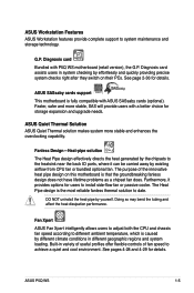
... away by effortlessly and quickly providing precise system checks right after they switch on this motherboard is fully compatible with P5Q WS motherboard (retail version), the G.P. See pages 4-28 and 4-29 for storage expansion and ...upgrade needs. Faster, safer and more stable and enhances the overclocking capability. The Heat Pipe design is caused by yourself. ASUS P5Q WS 1-5 ASUS Workstation Features ASUS Workstation features provide complete support to date. G.P. Fan Xpert ASUS...
... away by effortlessly and quickly providing precise system checks right after they switch on this motherboard is fully compatible with P5Q WS motherboard (retail version), the G.P. See pages 4-28 and 4-29 for storage expansion and ...upgrade needs. Faster, safer and more stable and enhances the overclocking capability. The Heat Pipe design is caused by yourself. ASUS P5Q WS 1-5 ASUS Workstation Features ASUS Workstation features provide complete support to date. G.P. Fan Xpert ASUS...

User Manual
Page 23
...ta��il�s�. 1.3.3 ASUS Intelligent Performance & Overclocking features AI Booster The ASUS AI Booster allows you to overclocking. ASUS P5Q WS 1-7 ASUS CrashFree BIOS 3 ASUS CrashFree BIOS 3 allows users to achieve... the most precise setting for the ultimate customized overclocking configuration. Precision Tweaker 2 Allows the user to adjust the NB Voltage, FSB termination Voltage, CPU PLL Voltage and the DRAM Voltage in Windows environment without the hassle of the motherboard...
...ta��il�s�. 1.3.3 ASUS Intelligent Performance & Overclocking features AI Booster The ASUS AI Booster allows you to overclocking. ASUS P5Q WS 1-7 ASUS CrashFree BIOS 3 ASUS CrashFree BIOS 3 allows users to achieve... the most precise setting for the ultimate customized overclocking configuration. Precision Tweaker 2 Allows the user to adjust the NB Voltage, FSB termination Voltage, CPU PLL Voltage and the DRAM Voltage in Windows environment without the hassle of the motherboard...

User Manual
Page 26
Chapter summary 2 2.1 Before you proceed 2-1 2.2 Motherboard overview 2-2 2.3 Central Processing Unit (CPU 2-5 2.4 System memory 2-11 2.5 Expansion slots 2-16 2.6 Jumpers 2-19 2.7 Connectors 2-22 2.8 G.P. Diagnosis card installation 2-36 2.9 Starting up for the first time 2-38 2.10 Turning off the computer 2-39 ASUS P5Q WS
Chapter summary 2 2.1 Before you proceed 2-1 2.2 Motherboard overview 2-2 2.3 Central Processing Unit (CPU 2-5 2.4 System memory 2-11 2.5 Expansion slots 2-16 2.6 Jumpers 2-19 2.7 Connectors 2-22 2.8 G.P. Diagnosis card installation 2-36 2.9 Starting up for the first time 2-38 2.10 Turning off the computer 2-39 ASUS P5Q WS

User Manual
Page 27
...indicate that the system is ON, in sleep mode, or in soft‑off or the power cord is switched off mode. ASUS P5Q WS 2-1 This is a reminder that the ATX power supply is detached from the wall socket before touching any component. • Use a grounded wrist strap or touch a safely... shut down the system and unplug the power cable before you uninstall any component, place it on a grounded antistatic pad or in any motherboard settings. • Unplug the power cord from the power supply. The illustration below shows the location of the following precautions before removing or...
...indicate that the system is ON, in sleep mode, or in soft‑off or the power cord is switched off mode. ASUS P5Q WS 2-1 This is a reminder that the ATX power supply is detached from the wall socket before touching any component. • Use a grounded wrist strap or touch a safely... shut down the system and unplug the power cable before you uninstall any component, place it on a grounded antistatic pad or in any motherboard settings. • Unplug the power cord from the power supply. The illustration below shows the location of the following precautions before removing or...

User Manual
Page 31
ASUS P5Q WS 2-5 2.3 Central Processing Unit (CPU) The motherboard comes with the cap on the socket and the socket contacts are unplugged before installing the CPU. &#... sure that the PnP cap is shipment/transit-related. • Keep the cap after installing the motherboard. ASUS will process Return Merchandise Authorization (RMA) requests only if the motherboard comes with a surface mount LGA775 socket designed for the Intel® Core™2 Extreme / Core™2 Quad... socket. • The product warranty does not cover damage to the PnP cap/socket contacts/motherboard components.
ASUS P5Q WS 2-5 2.3 Central Processing Unit (CPU) The motherboard comes with the cap on the socket and the socket contacts are unplugged before installing the CPU. &#... sure that the PnP cap is shipment/transit-related. • Keep the cap after installing the motherboard. ASUS will process Return Merchandise Authorization (RMA) requests only if the motherboard comes with a surface mount LGA775 socket designed for the Intel® Core™2 Extreme / Core™2 Quad... socket. • The product warranty does not cover damage to the PnP cap/socket contacts/motherboard components.

User Manual
Page 35
...includes the CPU fan and heatsink assembly. B 2. A B A A B B A 1 1 Orient the heatsink and fan assembly such that you have installed the motherboard to the chassis before you install the heatsink and fan assembly. ASUS P5Q WS 2-9 To install the CPU heatsink and fan: 1. 2.3.2 Installing the CPU heatsink and fan The Intel® LGA775 processor requires a specially... the heatsink and fan assembly. If you purchased a separate CPU heatsink and fan assembly, ensure that the four fasteners match the holes on the motherboard. Push down two fasteners at a time in place.
...includes the CPU fan and heatsink assembly. B 2. A B A A B B A 1 1 Orient the heatsink and fan assembly such that you have installed the motherboard to the chassis before you install the heatsink and fan assembly. ASUS P5Q WS 2-9 To install the CPU heatsink and fan: 1. 2.3.2 Installing the CPU heatsink and fan The Intel® LGA775 processor requires a specially... the heatsink and fan assembly. If you purchased a separate CPU heatsink and fan assembly, ensure that the four fasteners match the holes on the motherboard. Push down two fasteners at a time in place.

User Manual
Page 37
DDR2 DIMMs are notched differently to the 184-pin DDR DIMM. 2.4 System memory 2.4.1 Overview The motherboard comes with four Double Data Rate 2 (DDR2) Dual Inline Memory Modules (DIMM) sockets. The figure illustrates the location of the DDR2 DIMM sockets: Channel Channel A Channel B Sockets DIMM_A1 and DIMM_A2 DIMM_B1 and DIMM_B2 ASUS P5Q WS 2-11 A DDR2 module has the same physical dimensions as a DDR DIMM but has a 240-pin footprint compared to prevent installation on a DDR DIMM socket.
DDR2 DIMMs are notched differently to the 184-pin DDR DIMM. 2.4 System memory 2.4.1 Overview The motherboard comes with four Double Data Rate 2 (DDR2) Dual Inline Memory Modules (DIMM) sockets. The figure illustrates the location of the DDR2 DIMM sockets: Channel Channel A Channel B Sockets DIMM_A1 and DIMM_A2 DIMM_B1 and DIMM_B2 ASUS P5Q WS 2-11 A DDR2 module has the same physical dimensions as a DDR DIMM but has a 240-pin footprint compared to prevent installation on a DDR DIMM socket.

User Manual
Page 39
...8226;•• •• ••• • ••• ••• ••• ASUS P5Q WS 2-13 SS/ DS AD29608A8A-25EG SS AD26908A8A-25EG DS AD20908A8A-25EG DS AM4B5808CQJS8E SS AM4B5708JQJS8E SS AM4B5808CQJS8E DS Heat-Sink Package DS Heat-...SS K4T1G084QQ(ECC) SS K4T51083QG DS K4T1G084QQ(ECC) DS K4T1G084QQ DS Heat-Sink Package SS Heat-Sink Package DS Part No. P5Q WS Motherboard Qualified Vendors Lists (QVL) DDR2-800MHz capability Size 512MB 1024MB 2048MB 1024MB 512MB 2048MB 4096MB(Kit of 2) 4096MB(Kit of ...
...8226;•• •• ••• • ••• ••• ••• ASUS P5Q WS 2-13 SS/ DS AD29608A8A-25EG SS AD26908A8A-25EG DS AD20908A8A-25EG DS AM4B5808CQJS8E SS AM4B5708JQJS8E SS AM4B5808CQJS8E DS Heat-Sink Package DS Heat-...SS K4T1G084QQ(ECC) SS K4T51083QG DS K4T1G084QQ(ECC) DS K4T1G084QQ DS Heat-Sink Package SS Heat-Sink Package DS Part No. P5Q WS Motherboard Qualified Vendors Lists (QVL) DDR2-800MHz capability Size 512MB 1024MB 2048MB 1024MB 512MB 2048MB 4096MB(Kit of 2) 4096MB(Kit of ...

User Manual
Page 40
...;• TwinMOS TMM6208G8M30C SS 8D-23JK5M2ETP 5 ••• SS - Single-sided / DS - SS/ DS Part No. Visit the ASUS website for the latest DDR2-1066/800/667MHz QVL. 2-14 Chapter 2: Hardware information Double-sided DIMM support: • A*: Supports one module inserted... 512MB 1024MB 2048MB 1024MB 2048MB 2048MB 512MB 2048MB 1024MB 2048MB 512MB 1024MB 4096MB 512MB 1024MB 1024MB 2048MB 512MB Vendor Chip No. P5Q WS Motherboard Qualified Vendors Lists (QVL) DDR2-667MHz capability Size 512MB 1024MB 2048MB 1024MB 512MB 2048MB 512MB 1024MB 512MB 1024MB 1024MB 1024MB 512MB...
...;• TwinMOS TMM6208G8M30C SS 8D-23JK5M2ETP 5 ••• SS - Single-sided / DS - SS/ DS Part No. Visit the ASUS website for the latest DDR2-1066/800/667MHz QVL. 2-14 Chapter 2: Hardware information Double-sided DIMM support: • A*: Supports one module inserted... 512MB 1024MB 2048MB 1024MB 2048MB 2048MB 512MB 2048MB 1024MB 2048MB 512MB 1024MB 4096MB 512MB 1024MB 1024MB 2048MB 512MB Vendor Chip No. P5Q WS Motherboard Qualified Vendors Lists (QVL) DDR2-667MHz capability Size 512MB 1024MB 2048MB 1024MB 512MB 2048MB 512MB 1024MB 512MB 1024MB 1024MB 1024MB 512MB...

User Manual
Page 41
2.4.3 Installing a DIMM Make sure to both the motherboard and the components. Failure to do so may cause severe damage to unplug the power supply before adding or removing DIMMs or other system components. ... the DIMM is properly seated. Firmly insert the DIMM into a socket to unlock the DIMM. 1 DDR2 DIMM notch Support the DIMM lightly with extra force. 2. ASUS P5Q WS 2-15
2.4.3 Installing a DIMM Make sure to both the motherboard and the components. Failure to do so may cause severe damage to unplug the power supply before adding or removing DIMMs or other system components. ... the DIMM is properly seated. Firmly insert the DIMM into a socket to unlock the DIMM. 1 DDR2 DIMM notch Support the DIMM lightly with extra force. 2. ASUS P5Q WS 2-15

User Manual
Page 43
... 9 15 10 IRQ holder for PCI steering* IRQ holder for PCI steering* * These IRQs are usually available for this motherboard A B C D E F G H PCI1 shared - - - - - - - 1394 (FW322) - - - LAN 1 (8111C) shared - - - - - - - PCIEX16_2 shared - - - - - - - shared - - - - - shared USB 2.0 controller 2 - - ASUS P5Q WS 2-17 2.5.3 Interrupt assignments IRQ Priority Standard function 0 1 System timer 1 2 Keyboard controller 2 - PCIEX16_1 shared - - - - - - - PCIX_1 shared - - - - - - USB controller 3 - - USB...
... 9 15 10 IRQ holder for PCI steering* IRQ holder for PCI steering* * These IRQs are usually available for this motherboard A B C D E F G H PCI1 shared - - - - - - - 1394 (FW322) - - - LAN 1 (8111C) shared - - - - - - - PCIEX16_2 shared - - - - - - - shared - - - - - shared USB 2.0 controller 2 - - ASUS P5Q WS 2-17 2.5.3 Interrupt assignments IRQ Priority Standard function 0 1 System timer 1 2 Keyboard controller 2 - PCIEX16_1 shared - - - - - - - PCIX_1 shared - - - - - - USB controller 3 - - USB...

User Manual
Page 51
... modes to match the covered hole on each Ultra DMA 133/100 signal cable: blue, black, and gray. Connect the blue connector to the motherboard's IDE connector, then select one of device(s) Master Slave Master Slave Cable connector Black Black Gray Black or gray • Pin 20 on the... IDE connector is removed to configure your device. ASUS P5Q WS 2-25 If any device jumper is for Ultra DMA 133/100 IDE devices. This prevents incorrect insertion when you connect the IDE cable. • ...
... modes to match the covered hole on each Ultra DMA 133/100 signal cable: blue, black, and gray. Connect the blue connector to the motherboard's IDE connector, then select one of device(s) Master Slave Master Slave Cable connector Black Black Gray Black or gray • Pin 20 on the... IDE connector is removed to configure your device. ASUS P5Q WS 2-25 If any device jumper is for Ultra DMA 133/100 IDE devices. This prevents incorrect insertion when you connect the IDE cable. • ...

User Manual
Page 53
... a front panel USB cable to the USB connectors. USB connectors (10-1 pin USB78; ASUS P5Q WS 2-27 Connect the USB module cable to any of the system chassis. Connect the USB cable to ASUS Q-Connector (USB, blue) first, and then install the Q-Connector (USB) to a ...slot opening at the back of these connectors. USB1112) These connectors are for USB 2.0 ports. These USB connectors comply with USB 2.0 specification that supports up to 480 Mbps connection speed. USB910; Doing so will damage the motherboard...
... a front panel USB cable to the USB connectors. USB connectors (10-1 pin USB78; ASUS P5Q WS 2-27 Connect the USB module cable to any of the system chassis. Connect the USB cable to ASUS Q-Connector (USB, blue) first, and then install the Q-Connector (USB) to a ...slot opening at the back of these connectors. USB1112) These connectors are for USB 2.0 ports. These USB connectors comply with USB 2.0 specification that supports up to 480 Mbps connection speed. USB910; Doing so will damage the motherboard...

User Manual
Page 55
...air flow inside the system may damage the motherboard components. Do not place jumper caps on the motherboard, making sure that you install two VGA cards, we recommend that the black wire of each cable matches the ground pin of the connector. ASUS P5Q WS 2-29 These are not jumpers! CPU, ...;�th�e��f�a�n� connectors on the fan connectors! • Only the CPU_FAN and CHA_FAN 1/2 connectors support the ASUS Fan Xpert feature. • If you plug the rear chassis fan cable to the fan connectors. DO NOT forget to connect the fan...
...air flow inside the system may damage the motherboard components. Do not place jumper caps on the motherboard, making sure that you install two VGA cards, we recommend that the black wire of each cable matches the ground pin of the connector. ASUS P5Q WS 2-29 These are not jumpers! CPU, ...;�th�e��f�a�n� connectors on the fan connectors! • Only the CPU_FAN and CHA_FAN 1/2 connectors support the ASUS Fan Xpert feature. • If you plug the rear chassis fan cable to the fan connectors. DO NOT forget to connect the fan...

User Manual
Page 57
Connect one end of the motherboard's high-definition audio capability. • If you to receive stereo audio input from sound sources such as a CD-ROM, TV tuner, or MPEG card. ASUS P5Q WS 2-31 Refer to 3.5.3 Onboard Device Configuration for a chassis-mounted front panel audio I /O module cable to [AC97]. Optical drive audio connector (4-pin CD...
Connect one end of the motherboard's high-definition audio capability. • If you to receive stereo audio input from sound sources such as a CD-ROM, TV tuner, or MPEG card. ASUS P5Q WS 2-31 Refer to 3.5.3 Onboard Device Configuration for a chassis-mounted front panel audio I /O module cable to [AC97]. Optical drive audio connector (4-pin CD...

User Manual
Page 61
Refer to the instructions below to the system panel connector, making sure the orientation matches the labels on the motherboard. 3. Install the ASUS Q-Connector to install the ASUS QConnector. 1. ASUS P5Q WS 2-35 The front panel functions are now enabled. The figure shows the Q-Connector properly installed on the Q-Connector to know the detailed pin definitions, then...
Refer to the instructions below to the system panel connector, making sure the orientation matches the labels on the motherboard. 3. Install the ASUS Q-Connector to install the ASUS QConnector. 1. ASUS P5Q WS 2-35 The front panel functions are now enabled. The figure shows the Q-Connector properly installed on the Q-Connector to know the detailed pin definitions, then...


