
User Manual
Page 14
Chapter summary 1 1.1 Welcome!...1-1 1.2 Package contents 1-1 1.3 Special features 1-1 1.4 Before you proceed 1-5 1.5 Motherboard overview 1-6 1.6 Central Processing Unit (CPU 1-8 1.7 System memory 1-13 1.8 Expansion slots 1-20 1.9 Jumper...1-24 1.10 Connectors 1-26 P5Q-EM DO.indb 2 ASUS P5Q-EM DO 12/9/08 12:32:44 PM
Chapter summary 1 1.1 Welcome!...1-1 1.2 Package contents 1-1 1.3 Special features 1-1 1.4 Before you proceed 1-5 1.5 Motherboard overview 1-6 1.6 Central Processing Unit (CPU 1-8 1.7 System memory 1-13 1.8 Expansion slots 1-20 1.9 Jumper...1-24 1.10 Connectors 1-26 P5Q-EM DO.indb 2 ASUS P5Q-EM DO 12/9/08 12:32:44 PM

User Manual
Page 15
...motherboard package for the following items. Motherboard Cables Accessories Application DVD Documentation ASUS P5Q-EM DO Serial ATA power and signal cables for buying an ASUS® P5Q-EM DO motherboard! Retail version only) ASUS motherboard support DVD User guide If any of the above items is ... Q-Connector Kit (USB, 1394, system panel; The motherboard delivers a host of ASUS quality motherboards! 1.1 Welcome! Thank you start installing the motherboard, and hardware devices on the environment. ASUS P5Q-EM DO P5Q-EM DO.indb 1 1-1 12/9/08 12:32:47 PM Before you for 2 devices ...
...motherboard package for the following items. Motherboard Cables Accessories Application DVD Documentation ASUS P5Q-EM DO Serial ATA power and signal cables for buying an ASUS® P5Q-EM DO motherboard! Retail version only) ASUS motherboard support DVD User guide If any of the above items is ... Q-Connector Kit (USB, 1394, system panel; The motherboard delivers a host of ASUS quality motherboards! 1.1 Welcome! Thank you start installing the motherboard, and hardware devices on the environment. ASUS P5Q-EM DO P5Q-EM DO.indb 1 1-1 12/9/08 12:32:47 PM Before you for 2 devices ...

User Manual
Page 17
... technology that simultaneously sends different audio streams to analog format and keeps the best signal quality. it makes the change of TPM. ASUS P5Q-EM DO P5Q-EM DO.indb 3 1-3 12/9/08 12:33:04 PM Some third-party softwares may be requirred when running some functions of fan ... sound quality on your partners on the headphone while playing multi-channel network games See page 1-34 for details. 1.3.2 ASUS Features ASUS Quiet Thermal Solution ASUS Quiet Thermal solution makes system more smoothly. Moreover, Advanced Q-Fan has a better control over a constant temperature system environment...
... technology that simultaneously sends different audio streams to analog format and keeps the best signal quality. it makes the change of TPM. ASUS P5Q-EM DO P5Q-EM DO.indb 3 1-3 12/9/08 12:33:04 PM Some third-party softwares may be requirred when running some functions of fan ... sound quality on your partners on the headphone while playing multi-channel network games See page 1-34 for details. 1.3.2 ASUS Features ASUS Quiet Thermal Solution ASUS Quiet Thermal solution makes system more smoothly. Moreover, Advanced Q-Fan has a better control over a constant temperature system environment...

User Manual
Page 19
... antistatic pad or in the bag that came with a standby power LED that the system is switched off mode. SB_PWR P5Q-EM DO ON OFF Standby Power Powered Off P5Q-EM DO Onboard LED ASUS P5Q-EM DO P5Q-EM DO.indb 5 1-5 12/9/08 12:33:11 PM Failure to do so may cause severe damage to indicate that...
... antistatic pad or in the bag that came with a standby power LED that the system is switched off mode. SB_PWR P5Q-EM DO ON OFF Standby Power Powered Off P5Q-EM DO Onboard LED ASUS P5Q-EM DO P5Q-EM DO.indb 5 1-5 12/9/08 12:33:11 PM Failure to do so may cause severe damage to indicate that...

User Manual
Page 21
ASUS P5Q-EM DO P5Q-EM DO.indb 7 1-7 12/9/08 12:33:16 PM 24.4cm(9.6in) 1.5.3 Motherboard layout KBMS SPDIF_O2 SERVICE_MODE ATX12V 24.4cm(9.6in) F_USB34 LGA775 CPU_FAN Super I/O COM1 ...) DVI_VGA PRI_IDE EATXPWR USBPW1-4 CHA_FAN1 LAN1_USB12 AUDIO Intel® Q45 PCIEX1_1 Single Lan PCIEX16 PCIEX1_2 ICS 9LPRS 918JKLF Lithium Cell CMOS Power ALC 1200 AAFP P5Q-EM DO SPDIF_OUT CD PCI2 CLRTC USBPW9-12 IE1394_2 USB1112 CHASSIS Intel® ICH10DO SATA2 SATA4 SATA6 SB_PWR SATA1 SATA3 SATA5 PANEL USBPW5-8 USB910 USB56 USB78...
ASUS P5Q-EM DO P5Q-EM DO.indb 7 1-7 12/9/08 12:33:16 PM 24.4cm(9.6in) 1.5.3 Motherboard layout KBMS SPDIF_O2 SERVICE_MODE ATX12V 24.4cm(9.6in) F_USB34 LGA775 CPU_FAN Super I/O COM1 ...) DVI_VGA PRI_IDE EATXPWR USBPW1-4 CHA_FAN1 LAN1_USB12 AUDIO Intel® Q45 PCIEX1_1 Single Lan PCIEX16 PCIEX1_2 ICS 9LPRS 918JKLF Lithium Cell CMOS Power ALC 1200 AAFP P5Q-EM DO SPDIF_OUT CD PCI2 CLRTC USBPW9-12 IE1394_2 USB1112 CHASSIS Intel® ICH10DO SATA2 SATA4 SATA6 SB_PWR SATA1 SATA3 SATA5 PANEL USBPW5-8 USB910 USB56 USB78...

User Manual
Page 23
... it is on the socket and damaging the CPU! Lift the load lever in only one correct orientation. 2. CPU notch Gold triangle mark Alignment key ASUS P5Q-EM DO P5Q-EM DO.indb 9 1-9 12/9/08 12:33:22 PM The CPU fits in the direction of the arrow to the left corner of the socket...
... it is on the socket and damaging the CPU! Lift the load lever in only one correct orientation. 2. CPU notch Gold triangle mark Alignment key ASUS P5Q-EM DO P5Q-EM DO.indb 9 1-9 12/9/08 12:33:22 PM The CPU fits in the direction of the arrow to the left corner of the socket...

User Manual
Page 25
... Intel® processor, the package includes the CPU fan and heatsink assembly. Make sure that the four fasteners match the holes on the motherboard. ASUS P5Q-EM DO P5Q-EM DO.indb 11 1-11 12/9/08 12:33:29 PM To install the CPU heatsink and fan: 1. Place the heatsink on top of CPU heatsink...
... Intel® processor, the package includes the CPU fan and heatsink assembly. Make sure that the four fasteners match the holes on the motherboard. ASUS P5Q-EM DO P5Q-EM DO.indb 11 1-11 12/9/08 12:33:29 PM To install the CPU heatsink and fan: 1. Place the heatsink on top of CPU heatsink...
User Manual
Page 27
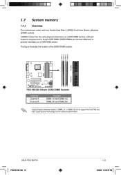
... DIMM but has a 240-pin footprint compared to prevent installation on a DDR DIMM socket. DDR2 DIMMs are notched differently to the 184-pin DDR DIMM. ASUS P5Q-EM DO P5Q-EM DO.indb 13 1-13 12/9/08 12:33:40 PM 1.7 System memory 1.7.1 Overview The motherboard comes with four Double Data Rate 2 (DDR2) Dual Inline...
... DIMM but has a 240-pin footprint compared to prevent installation on a DDR DIMM socket. DDR2 DIMMs are notched differently to the 184-pin DDR DIMM. ASUS P5Q-EM DO P5Q-EM DO.indb 13 1-13 12/9/08 12:33:40 PM 1.7 System memory 1.7.1 Overview The motherboard comes with four Double Data Rate 2 (DDR2) Dual Inline...

User Manual
Page 29
ASUS P5Q-EM DO P5Q-EM DO.indb 15 1-15 12/9/08 12:33:43 PM Notes on memory limitations • Due to chipset limitation, this motherboard can only support up ...
ASUS P5Q-EM DO P5Q-EM DO.indb 15 1-15 12/9/08 12:33:43 PM Notes on memory limitations • Due to chipset limitation, this motherboard can only support up ...

User Manual
Page 33
... direction. Failure to do so can cause severe damage to avoid damaging the DIMM. 3. Locked retaining clip 2 Support the DIMM lightly with 1 extra force. ASUS P5Q-EM DO 1 1-19 P5Q-EM DO.indb 19 12/9/08 12:34:00 PM Firmly insert the DIMM into a socket to both the motherboard and the components. 1. Simultaneously press...
... direction. Failure to do so can cause severe damage to avoid damaging the DIMM. 3. Locked retaining clip 2 Support the DIMM lightly with 1 extra force. ASUS P5Q-EM DO 1 1-19 P5Q-EM DO.indb 19 12/9/08 12:34:00 PM Firmly insert the DIMM into a socket to both the motherboard and the components. 1. Simultaneously press...

User Manual
Page 35
... data processor 14 9 IRQ holder for PCI steering* 15 10 IRQ holder for PCI steering* * These IRQs are usually available for ISA or PCI devices. ASUS P5Q-EM DO P5Q-EM DO.indb 21 1-21 12/9/08 12:34:01 PM 1.8.3 Interrupt assignments Standard interrupt assignments IRQ Priority Standard function 0 1 System timer 1 2 Keyboard controller...
... data processor 14 9 IRQ holder for PCI steering* 15 10 IRQ holder for PCI steering* * These IRQs are usually available for ISA or PCI devices. ASUS P5Q-EM DO P5Q-EM DO.indb 21 1-21 12/9/08 12:34:01 PM 1.8.3 Interrupt assignments Standard interrupt assignments IRQ Priority Standard function 0 1 System timer 1 2 Keyboard controller...

User Manual
Page 37
..., SCSI card, USB card, and other cards that comply with the PCI Express specifications. PCI slot PCIe x1 slot PCIe 2.0 x16 slot PCIe x1 slot ASUS P5Q-EM DO P5Q-EM DO.indb 23 1-23 12/9/08 12:34:08 PM The figure shows a LAN card installed on the PCI Express x16 slot.
..., SCSI card, USB card, and other cards that comply with the PCI Express specifications. PCI slot PCIe x1 slot PCIe 2.0 x16 slot PCIe x1 slot ASUS P5Q-EM DO P5Q-EM DO.indb 23 1-23 12/9/08 12:34:08 PM The figure shows a LAN card installed on the PCI Express x16 slot.

User Manual
Page 39
...no power to wake up from S1 sleep mode (CPU stopped, DRAM refreshed, system running in low power mode) using the connected USB devices. ASUS P5Q-EM DO P5Q-EM DO.indb 25 1-25 12/9/08 12:34:13 PM otherwise, the system would not power up feature requires a power supply that can provide 500mA... on the +5VSB lead for each USB port; USBPW1-4 12 23 +5V +5VSB (Default) USBPW9-12 12 23 P5Q-EM DO +5V +5VSB (Default) P5Q-EM DO USB Device Wake Up USBPW5-8 12 23 +5V +5VSB (Default) • The USB device wake-up . • The total current consumed...
...no power to wake up from S1 sleep mode (CPU stopped, DRAM refreshed, system running in low power mode) using the connected USB devices. ASUS P5Q-EM DO P5Q-EM DO.indb 25 1-25 12/9/08 12:34:13 PM otherwise, the system would not power up feature requires a power supply that can provide 500mA... on the +5VSB lead for each USB port; USBPW1-4 12 23 +5V +5VSB (Default) USBPW9-12 12 23 P5Q-EM DO +5V +5VSB (Default) P5Q-EM DO USB Device Wake Up USBPW5-8 12 23 +5V +5VSB (Default) • The USB device wake-up . • The total current consumed...

User Manual
Page 41
... Mic In Center/Subwoofer Rear Speaker Out Side Speaker Out 13. DVI port. USB 2.0 ports 3 and 4. This port is for connecting USB 2.0 devices. 14. ASUS P5Q-EM DO P5Q-EM DO.indb 27 1-27 12/9/08 12:34:20 PM In 4-channel, 6channel, and 8-channel configuration, the function of the audio ports in an 8-channel...
... Mic In Center/Subwoofer Rear Speaker Out Side Speaker Out 13. DVI port. USB 2.0 ports 3 and 4. This port is for connecting USB 2.0 devices. 14. ASUS P5Q-EM DO P5Q-EM DO.indb 27 1-27 12/9/08 12:34:20 PM In 4-channel, 6channel, and 8-channel configuration, the function of the audio ports in an 8-channel...

User Manual
Page 43
IE1394_2 PIN 1 P5Q-EM DO P5Q-EM DO IEEE 1394 connector The IEEE 1394a module is for a IEEE 1394a port. 3. IEEE 1394a port connector (10-1 pin IE1394_2) This connector is purchased separately. Connect the IEEE 1394a module cable to this connector, then install the module to a slot opening at the back of the system chassis. TPA2GND TPB2+12V GND TPA2+ GND TPB2+ +12V ASUS P5Q-EM DO P5Q-EM DO.indb 29 1-29 12/9/08 12:34:31 PM
IE1394_2 PIN 1 P5Q-EM DO P5Q-EM DO IEEE 1394 connector The IEEE 1394a module is for a IEEE 1394a port. 3. IEEE 1394a port connector (10-1 pin IE1394_2) This connector is purchased separately. Connect the IEEE 1394a module cable to this connector, then install the module to a slot opening at the back of the system chassis. TPA2GND TPB2+12V GND TPA2+ GND TPB2+ +12V ASUS P5Q-EM DO P5Q-EM DO.indb 29 1-29 12/9/08 12:34:31 PM

User Manual
Page 45
...the right-angle side of SATA signal cable to SATA device. CD Left Audio Channel GND GND Right Audio Channel P5Q-EM DO P5Q-EM DO Internal audio connector ASUS P5Q-EM DO P5Q-EM DO.indb 31 1-31 12/9/08 12:34:37 PM right angle side 6. 5. SATA2 SATA1 GND RSATA_RXN2 RSATA_RXP2... RSATA_RXP3 GND RSATA_TXN3 RSATA_TXP3 GND SATA6 SATA5 GND RSATA_RXN6 RSATA_RXP6 GND RSATA_TXN6 RSATA_TXP6 GND GND RSATA_RXN5 RSATA_RXP5 GND RSATA_TXN5 RSATA_TXP5 GND P5Q-EM DO P5Q-EM DO SATA connectors(ICH10DO®) Connect the right-angle side of SATA cable to the onboard SATA port to receive stereo...
...the right-angle side of SATA signal cable to SATA device. CD Left Audio Channel GND GND Right Audio Channel P5Q-EM DO P5Q-EM DO Internal audio connector ASUS P5Q-EM DO P5Q-EM DO.indb 31 1-31 12/9/08 12:34:37 PM right angle side 6. 5. SATA2 SATA1 GND RSATA_RXN2 RSATA_RXP2... RSATA_RXP3 GND RSATA_TXN3 RSATA_TXP3 GND SATA6 SATA5 GND RSATA_RXN6 RSATA_RXP6 GND RSATA_TXN6 RSATA_TXP6 GND GND RSATA_RXN5 RSATA_RXP5 GND RSATA_TXN5 RSATA_TXP5 GND P5Q-EM DO P5Q-EM DO SATA connectors(ICH10DO®) Connect the right-angle side of SATA cable to the onboard SATA port to receive stereo...

User Manual
Page 47
... Q-Fan feature. Connect the fan cables to use the chassis intrusion detection feature. +5VSB_MB Chassis Signal GND P5Q-EM DO CHASSIS P5Q-EM DO Chassis intrusion connector ASUS P5Q-EM DO P5Q-EM DO.indb 33 1-33 12/9/08 12:34:48 PM Chassis intrusion connector (4-1 pin CHASSIS) This connector is then generated as a chassis intrusion event. The ...
... Q-Fan feature. Connect the fan cables to use the chassis intrusion detection feature. +5VSB_MB Chassis Signal GND P5Q-EM DO CHASSIS P5Q-EM DO Chassis intrusion connector ASUS P5Q-EM DO P5Q-EM DO.indb 33 1-33 12/9/08 12:34:48 PM Chassis intrusion connector (4-1 pin CHASSIS) This connector is then generated as a chassis intrusion event. The ...

User Manual
Page 49
... system power, and blinks when the system is in sleep or soft-off the system power. PWR Ground Reset Ground P5Q-EM DO IDE_LED PWRSW RESET * Requires an ATX power supply P5Q-EM DO System panel connector • System power LED (2-pin PLED) This 2-pin connector is for system reboot without turning... • ATX power button/soft-off button (2-pin PWRSW) This connector is for the chassis-mounted reset button for the system power LED. ASUS P5Q-EM DO P5Q-EM DO.indb 35 1-35 12/9/08 12:34:52 PM Pressing the power button turns the system on the BIOS settings. PLED SPEAKER PLED+ ...
... system power, and blinks when the system is in sleep or soft-off the system power. PWR Ground Reset Ground P5Q-EM DO IDE_LED PWRSW RESET * Requires an ATX power supply P5Q-EM DO System panel connector • System power LED (2-pin PLED) This 2-pin connector is for system reboot without turning... • ATX power button/soft-off button (2-pin PWRSW) This connector is for the chassis-mounted reset button for the system power LED. ASUS P5Q-EM DO P5Q-EM DO.indb 35 1-35 12/9/08 12:34:52 PM Pressing the power button turns the system on the BIOS settings. PLED SPEAKER PLED+ ...

User Manual
Page 52
Chapter summary 2 2.1 Managing and updating your BIOS 2-1 2.2 BIOS setup program 2-10 2.3 Main menu 2-13 2.4 Ai Tweaker menu 2-17 2.5 Advanced menu 2-21 2.6 Power menu 2-31 2.7 Boot menu 2-35 2.8 Tools menu 2-39 2.9 Exit menu 2-40 2.10 Intel® ME configuration 2-41 P5Q-EM DO.indb 2 ASUS P5Q-EM DO 12/9/08 12:35:01 PM
Chapter summary 2 2.1 Managing and updating your BIOS 2-1 2.2 BIOS setup program 2-10 2.3 Main menu 2-13 2.4 Ai Tweaker menu 2-17 2.5 Advanced menu 2-21 2.6 Power menu 2-31 2.7 Boot menu 2-35 2.8 Tools menu 2-39 2.9 Exit menu 2-40 2.10 Intel® ME configuration 2-41 P5Q-EM DO.indb 2 ASUS P5Q-EM DO 12/9/08 12:35:01 PM

User Manual
Page 53
...flash disk.) 2. Select the 3 1/2 Floppy Drive icon. DOS environment a. b. Click Start from the Windows® desktop, then select Computer. ASUS AFUDOS (Updates the BIOS in Windows® environment.) Refer to the corresponding sections for details on these utilities. b. e. Do either one of the...the floppy disk drive. d. Select the Create an MS-DOS startup disk check box. ASUS P5Q-EM DO 2-1 P5Q-EM DO.indb 1 12/9/08 12:35:04 PM ASUS EZ Flash 2 (Updates the BIOS using the ASUS Update or AFUDOS utilities. 2.1.1 Creating a bootable floppy disk 1. Save a copy of...
...flash disk.) 2. Select the 3 1/2 Floppy Drive icon. DOS environment a. b. Click Start from the Windows® desktop, then select Computer. ASUS AFUDOS (Updates the BIOS in Windows® environment.) Refer to the corresponding sections for details on these utilities. b. e. Do either one of the...the floppy disk drive. d. Select the Create an MS-DOS startup disk check box. ASUS P5Q-EM DO 2-1 P5Q-EM DO.indb 1 12/9/08 12:35:04 PM ASUS EZ Flash 2 (Updates the BIOS using the ASUS Update or AFUDOS utilities. 2.1.1 Creating a bootable floppy disk 1. Save a copy of...


