
User Manual
Page 1
Motherboard P5P43TD/USB3
Motherboard P5P43TD/USB3

User Manual
Page 3
Contents Notices...vi Safety information vii About this guide vii P5P43TD/USB3 specifications summary ix Chapter 1: Product introduction 1.1 Welcome 1-1 1.2 Package contents 1-1 1.3 Special features 1-1 1.3.1 Product highlights 1-1 1.3.2 Innovative ASUS features 1-2 1.4 Before you proceed 1-4 1.5 Motherboard overview 1-5 1.5.1 Placement direction 1-5 1.5.2 Screw holes 1-5 1.5.3 Motherboard layout 1-6 1.5.4 Layout contents 1-6 1.6 Central Processing Unit (CPU 1-7 1.6.1 Installing the CPU 1-7 1.6.2 Installing the CPU heatsink and fan 1-10 1.6.3 Uninstalling...
Contents Notices...vi Safety information vii About this guide vii P5P43TD/USB3 specifications summary ix Chapter 1: Product introduction 1.1 Welcome 1-1 1.2 Package contents 1-1 1.3 Special features 1-1 1.3.1 Product highlights 1-1 1.3.2 Innovative ASUS features 1-2 1.4 Before you proceed 1-4 1.5 Motherboard overview 1-5 1.5.1 Placement direction 1-5 1.5.2 Screw holes 1-5 1.5.3 Motherboard layout 1-6 1.5.4 Layout contents 1-6 1.6 Central Processing Unit (CPU 1-7 1.6.1 Installing the CPU 1-7 1.6.2 Installing the CPU heatsink and fan 1-10 1.6.3 Uninstalling...

User Manual
Page 6
... been designed to provide reasonable protection against harmful interference in our products at ASUS REACH website at http://green.asus.com/english/REACH.htm. Notices Federal Communications Commission Statement This device complies with Canadian ICES-003. DO NOT throw the motherboard in municipal waste. Canadian Department of Communications. Check local regulations for radio...
... been designed to provide reasonable protection against harmful interference in our products at ASUS REACH website at http://green.asus.com/english/REACH.htm. Notices Federal Communications Commission Statement This device complies with Canadian ICES-003. DO NOT throw the motherboard in municipal waste. Canadian Department of Communications. Check local regulations for radio...

User Manual
Page 7
...parts: • Chapter 1: Product introduction This chapter describes the features of the electrical outlet you need when installing and configuring the motherboard. If you encounter technical problems with the package. • Before using the product, ensure that all power cables from the ...in any damage, contact your dealer immediately. • To avoid short circuits, keep paper clips, screws, and staples away from the motherboard, ensure that all the manuals that came with the product, contact a qualified service technician or your area. These devices could interrupt ...
...parts: • Chapter 1: Product introduction This chapter describes the features of the electrical outlet you need when installing and configuring the motherboard. If you encounter technical problems with the package. • Before using the product, ensure that all power cables from the ...in any damage, contact your dealer immediately. • To avoid short circuits, keep paper clips, screws, and staples away from the motherboard, ensure that all the manuals that came with the product, contact a qualified service technician or your area. These devices could interrupt ...

User Manual
Page 11
... line of the above items is damaged or missing, contact your motherboard package for the following items. Motherboard Cables Accessories Application DVD Documentation ASUS P5P43TD/USB3 motherboard 2 x Serial ATA cables 1 x Ultra DMA 133/100/66 cable 1 x I/O shield ASUS motherboard support DVD User Manual If any of ASUS quality motherboards! Chapter 1 Product introduction 1.1 Welcome! Before you for multitasking, multimedia, and enthusiastic...
... line of the above items is damaged or missing, contact your motherboard package for the following items. Motherboard Cables Accessories Application DVD Documentation ASUS P5P43TD/USB3 motherboard 2 x Serial ATA cables 1 x Ultra DMA 133/100/66 cable 1 x I/O shield ASUS motherboard support DVD User Manual If any of ASUS quality motherboards! Chapter 1 Product introduction 1.1 Welcome! Before you for multitasking, multimedia, and enthusiastic...

User Manual
Page 12
... home theater audio systems via the S/PDIF-out (SONY-PHILIPS Digital Interface) jack. ASUS Anti-Surge Protection This special design prevents expensive devices and the motherboard from switching power supply (PSU). 1-2 Chapter 1: Product introduction S/PDIF digital sound ready This motherboard provides convenient connectivity to save power and money. Gigabit LAN solution The onboard...
... home theater audio systems via the S/PDIF-out (SONY-PHILIPS Digital Interface) jack. ASUS Anti-Surge Protection This special design prevents expensive devices and the motherboard from switching power supply (PSU). 1-2 Chapter 1: Product introduction S/PDIF digital sound ready This motherboard provides convenient connectivity to save power and money. Gigabit LAN solution The onboard...
User Manual
Page 13
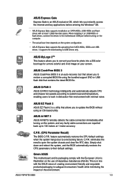
...motherboard USB port before entering the Windows® OS. • ASUS Express Gate supports installation on SATA HDDs, USB HDDs and flash drives with at 1 meter accuracy. It supports file downloading to open the system chassis and clear the RTC data. This is in distraction-free environment with minimal noise. ASUS P5P43TD/USB3... 1-3 When installing it on USB HDDs or flash drives, connect the drives to safeguard consumers' health while minimizing the impact on the environment. ASUS AI NET 2 ASUS AI NET2 remotely detects the...
...motherboard USB port before entering the Windows® OS. • ASUS Express Gate supports installation on SATA HDDs, USB HDDs and flash drives with at 1 meter accuracy. It supports file downloading to open the system chassis and clear the RTC data. This is in distraction-free environment with minimal noise. ASUS P5P43TD/USB3... 1-3 When installing it on USB HDDs or flash drives, connect the drives to safeguard consumers' health while minimizing the impact on the environment. ASUS AI NET 2 ASUS AI NET2 remotely detects the...

User Manual
Page 14
...Take note of the onboard LED. 1-4 Chapter 1: Product introduction Onboard LED The motherboard comes with the component. • Before you install or remove any component, ensure that you install motherboard components or change any motherboard settings. • Unplug the power cord from the power supply. This is ... is a reminder that the ATX power supply is switched off mode. Failure to do so may cause severe damage to the motherboard, peripherals, or components. The illustration below shows the location of the following precautions before you must shut down the system and ...
...Take note of the onboard LED. 1-4 Chapter 1: Product introduction Onboard LED The motherboard comes with the component. • Before you install or remove any component, ensure that you install motherboard components or change any motherboard settings. • Unplug the power cord from the power supply. This is ... is a reminder that the ATX power supply is switched off mode. Failure to do so may cause severe damage to the motherboard, peripherals, or components. The illustration below shows the location of the following precautions before you must shut down the system and ...
User Manual
Page 15
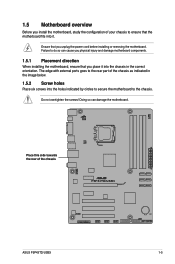
... cause you physical injury and damage motherboard components. 1.5.1 Placement direction When installing the motherboard, ensure that you unplug the power cord before installing or removing the motherboard. Do not overtighten the screws! Place...motherboard fits into it into the chassis in the image below. 1.5.2 Screw holes Place six screws into the holes indicated by circles to secure the motherboard to do so can damage the motherboard. Failure to the chassis. 1.5 Motherboard overview Before you install the motherboard, study the configuration of the chassis ASUS P5P43TD/USB3...
... cause you physical injury and damage motherboard components. 1.5.1 Placement direction When installing the motherboard, ensure that you unplug the power cord before installing or removing the motherboard. Do not overtighten the screws! Place...motherboard fits into it into the chassis in the image below. 1.5.2 Screw holes Place six screws into the holes indicated by circles to secure the motherboard to do so can damage the motherboard. Failure to the chassis. 1.5 Motherboard overview Before you install the motherboard, study the configuration of the chassis ASUS P5P43TD/USB3...

User Manual
Page 16
... (7-pin SATA1-6) 1-23 12. Onboard LED (SB_PWR) 1-4 13. Clear RTC RAM (3-pin CLRTC) 1-19 1-6 Chapter 1: Product introduction USB connectors (10-1 pin USB78, USB910, 1-26 USB1112) 4. 1.5.3 Motherboard layout 1.5.4 Layout contents Connectors/Jumpers/Slots/LED Page Connectors/Jumpers/Slots/LED Page 1. IDE connector (40-1 pin PRI_EIDE) 1-24 ATX12V) 3.
... (7-pin SATA1-6) 1-23 12. Onboard LED (SB_PWR) 1-4 13. Clear RTC RAM (3-pin CLRTC) 1-19 1-6 Chapter 1: Product introduction USB connectors (10-1 pin USB78, USB910, 1-26 USB1112) 4. 1.5.3 Motherboard layout 1.5.4 Layout contents Connectors/Jumpers/Slots/LED Page Connectors/Jumpers/Slots/LED Page 1. IDE connector (40-1 pin PRI_EIDE) 1-24 ATX12V) 3.

User Manual
Page 17
... the cost of the PnP cap. ASUS P5P43TD/USB3 1-7 Before installing the CPU, ensure that the PnP cap is shipment/transit-related. • Keep the cap after installing the motherboard. ASUS will process Return Merchandise Authorization (RMA) requests only if the motherboard comes with the cap on the LGA775 socket. • The product warranty does not...
... the cost of the PnP cap. ASUS P5P43TD/USB3 1-7 Before installing the CPU, ensure that the PnP cap is shipment/transit-related. • Keep the cap after installing the motherboard. ASUS will process Return Merchandise Authorization (RMA) requests only if the motherboard comes with the cap on the LGA775 socket. • The product warranty does not...

User Manual
Page 20
... may differ, but the installation steps and functions should remain the same. To install the CPU heatsink and fan: A 1. Place the heatsink on the motherboard. If you buy a boxed Intel® processor, the package includes the CPU fan and heatsink assembly. Ensure that you have installed the... motherboard to the CPU heatsink or CPU before you install the heatsink and fan assembly. Push down two fasteners at a time in a diagonal sequence to ...
... may differ, but the installation steps and functions should remain the same. To install the CPU heatsink and fan: A 1. Place the heatsink on the motherboard. If you buy a boxed Intel® processor, the package includes the CPU fan and heatsink assembly. Ensure that you have installed the... motherboard to the CPU heatsink or CPU before you install the heatsink and fan assembly. Push down two fasteners at a time in a diagonal sequence to ...

User Manual
Page 21
Disconnect the CPU fan cable from the motherboard. Pull up two fasteners at a time in a diagonal sequence to the connector on the motherboard. 2. Hardware monitoring errors can occur if you fail to connect the CPU fan connector! 3. Do not forget to plug this connector. 1.6.3 Uninstalling the CPU heatsink and fan To uninstall the CPU heatsink and fan: 1. Rotate each fastener counterclockwise. 3. A B A B B A B A ASUS P5P43TD/USB3 1-11 Connect the CPU fan cable to disengage the heatsink and fan assembly from the connector on the motherboard labeled CPU_FAN.
Disconnect the CPU fan cable from the motherboard. Pull up two fasteners at a time in a diagonal sequence to the connector on the motherboard. 2. Hardware monitoring errors can occur if you fail to connect the CPU fan connector! 3. Do not forget to plug this connector. 1.6.3 Uninstalling the CPU heatsink and fan To uninstall the CPU heatsink and fan: 1. Rotate each fastener counterclockwise. 3. A B A B B A B A ASUS P5P43TD/USB3 1-11 Connect the CPU fan cable to disengage the heatsink and fan assembly from the connector on the motherboard labeled CPU_FAN.

User Manual
Page 22
Carefully remove the heatsink and fan assembly from the motherboard. 5. Rotate each fastener clockwise to prevent installation on a DDR2 DIMM socket. 4. DDR3 modules are developed for better performance with four Double Data Rate 3 (DDR3) Dual ... introduction A DDR3 module has the same physical dimensions as a DDR2 DIMM but is notched differently to ensure correct orientation when reinstalling. 1.7 System memory 1.7.1 Overview This motherboard comes with less power consumption.
Carefully remove the heatsink and fan assembly from the motherboard. 5. Rotate each fastener clockwise to prevent installation on a DDR2 DIMM socket. 4. DDR3 modules are developed for better performance with four Double Data Rate 3 (DDR3) Dual ... introduction A DDR3 module has the same physical dimensions as a DDR2 DIMM but is notched differently to ensure correct orientation when reinstalling. 1.7 System memory 1.7.1 Overview This motherboard comes with less power consumption.

User Manual
Page 23
... you want to the memory address limitation on 32-bit Windows® OS, when you are using a 32-bit Windows® OS. - P5P43TD/USB3 Motherboard Qualified Vendors Lists (QVL) DDR3-1600 (O.C.) MHz capability Vendor Part No. The system maps the total size of 256 megabits (Mb) chips or...the next page) ASUS P5P43TD/USB3 1-13 For optimum compatibility, it is then mapped for single-channel operation. • Always install DIMMs with the same CAS latency. Any excess memory from the same vendor. • Due to install 4GB or more memory on the motherboard, the actual usable...
... you want to the memory address limitation on 32-bit Windows® OS, when you are using a 32-bit Windows® OS. - P5P43TD/USB3 Motherboard Qualified Vendors Lists (QVL) DDR3-1600 (O.C.) MHz capability Vendor Part No. The system maps the total size of 256 megabits (Mb) chips or...the next page) ASUS P5P43TD/USB3 1-13 For optimum compatibility, it is then mapped for single-channel operation. • Always install DIMMs with the same CAS latency. Any excess memory from the same vendor. • Due to install 4GB or more memory on the motherboard, the actual usable...

User Manual
Page 27
...unlock the DIMM. 2 Support the DIMM lightly with extra force. 1 2. To install a DIMM: 1. Remove the DIMM from the socket. 1 DIMM notch ASUS P5P43TD/USB3 1-17 Locked Retaining Clip 1.7.4 Removing a DIMM To remove a DIMM: 1. Simultaneously press the retaining clips outward to avoid damaging the DIMM. 3. The DIMM might...Failure to do so can cause severe damage to unlock a DIMM socket. 2. Press the retaining clips outward to both the motherboard and the components. 1.7.3 Installing a DIMM Unplug the power supply before adding or removing DIMMs or other system components.
...unlock the DIMM. 2 Support the DIMM lightly with extra force. 1 2. To install a DIMM: 1. Remove the DIMM from the socket. 1 DIMM notch ASUS P5P43TD/USB3 1-17 Locked Retaining Clip 1.7.4 Removing a DIMM To remove a DIMM: 1. Simultaneously press the retaining clips outward to avoid damaging the DIMM. 3. The DIMM might...Failure to do so can cause severe damage to unlock a DIMM socket. 2. Press the retaining clips outward to both the motherboard and the components. 1.7.3 Installing a DIMM Unplug the power supply before adding or removing DIMMs or other system components.

User Manual
Page 28
...need IRQ assignments. See Chapter 2 for the expansion card. 1.8 Expansion slots In the future, you may cause you physical injury and damage motherboard components. 1.8.1 Installing an expansion card To install an expansion card: 1. Install the software drivers for information on the slot. 5. When ... power cord before adding or removing expansion cards. Keep the screw for the card. 2. Remove the system unit cover (if your motherboard is completely seated on BIOS setup. 2. Before installing the expansion card, read the documentation that you intend to the chassis with the...
...need IRQ assignments. See Chapter 2 for the expansion card. 1.8 Expansion slots In the future, you may cause you physical injury and damage motherboard components. 1.8.1 Installing an expansion card To install an expansion card: 1. Install the software drivers for information on the slot. 5. When ... power cord before adding or removing expansion cards. Keep the screw for the card. 2. Remove the system unit cover (if your motherboard is completely seated on BIOS setup. 2. Before installing the expansion card, read the documentation that you intend to the chassis with the...

User Manual
Page 31
USB 2.0 ports 1 and 2. COM port. Do not forget to connect the fan cables to the fan connectors on the fan connectors! ASUS P5P43TD/USB3 1-21 These two 4-pin Universal Serial Bus (USB) ports are not jumpers! This 9-pin COM1 port is for a PS/2 keyboard. 1.10.2 Internal connectors... 3.0 devices. 8. This port connects an external audio output device via an optical S/PDIF cable. 11. Do not place jumper caps on the motherboard, ensuring that the black wire of each cable matches the ground pin of the connector. These two 4-pin Universal Serial Bus (USB) ports are...
USB 2.0 ports 1 and 2. COM port. Do not forget to connect the fan cables to the fan connectors on the fan connectors! ASUS P5P43TD/USB3 1-21 These two 4-pin Universal Serial Bus (USB) ports are not jumpers! This 9-pin COM1 port is for a PS/2 keyboard. 1.10.2 Internal connectors... 3.0 devices. 8. This port connects an external audio output device via an optical S/PDIF cable. 11. Do not place jumper caps on the motherboard, ensuring that the black wire of each cable matches the ground pin of the connector. These two 4-pin Universal Serial Bus (USB) ports are...

User Manual
Page 33
.../s is for a chassis-mounted front panel audio I/O module that you want to connect an AC'97 front panel audio module to [AC97]. ASUS P5P43TD/USB3 1-23 Connect one end of the motherboard's high-definition audio capability. • If you connect a high-definition front panel audio module to this connector to avail of the front...
.../s is for a chassis-mounted front panel audio I/O module that you want to connect an AC'97 front panel audio module to [AC97]. ASUS P5P43TD/USB3 1-23 Connect one end of the motherboard's high-definition audio capability. • If you connect a high-definition front panel audio module to this connector to avail of the front...

User Manual
Page 34
... device. IDE connector (40-1 pin PRI_EIDE) The onboard IDE connector is for Ultra DMA 133/100/66 IDE devices. Connect the blue connector to the motherboard's IDE connector, then select one of device(s) Master Slave Master Slave Cable connector Black Black Gray Black or gray • Pin 20 on the IDE...
... device. IDE connector (40-1 pin PRI_EIDE) The onboard IDE connector is for Ultra DMA 133/100/66 IDE devices. Connect the blue connector to the motherboard's IDE connector, then select one of device(s) Master Slave Master Slave Cable connector Black Black Gray Black or gray • Pin 20 on the IDE...


