
User Manual
Page 1
P5P41TD Motherboard
P5P41TD Motherboard
User Manual
Page 3
Contents Notices...vi Safety information vii About this guide vii P5P41TD specifications summary ix Chapter 1: Product introduction 1.1 Welcome 1-1 1.2 Package contents 1-1 1.3 Special features 1-1 1.3.1 Product highlights 1-1 1.3.2 Innovative ASUS features 1-2 1.4 Before you proceed 1-4 1.5 Motherboard overview 1-5 1.5.1 Placement direction 1-5 1.5.2 Screw holes 1-5 1.5.3 Motherboard layout 1-6 1.5.4 Layout contents 1-6 1.6 Central Processing Unit (CPU 1-7 1.6.1 Installing the CPU 1-7 1.6.2 Installing the CPU heatsink and fan 1-10 1.6.3 Uninstalling...
Contents Notices...vi Safety information vii About this guide vii P5P41TD specifications summary ix Chapter 1: Product introduction 1.1 Welcome 1-1 1.2 Package contents 1-1 1.3 Special features 1-1 1.3.1 Product highlights 1-1 1.3.2 Innovative ASUS features 1-2 1.4 Before you proceed 1-4 1.5 Motherboard overview 1-5 1.5.1 Placement direction 1-5 1.5.2 Screw holes 1-5 1.5.3 Motherboard layout 1-6 1.5.4 Layout contents 1-6 1.6 Central Processing Unit (CPU 1-7 1.6.1 Installing the CPU 1-7 1.6.2 Installing the CPU heatsink and fan 1-10 1.6.3 Uninstalling...

User Manual
Page 6
These limits are designed to assure compliance with the limits for connection of Communications. DO NOT throw the motherboard in municipal waste. If this equipment does cause harmful interference to an outlet on , the user is connected. • Consult the dealer ...Evaluation, Authorisation, and Restriction of the crossed out wheeled bin indicates that the battery should not be placed in our products at ASUS REACH website at http://green.asus.com/english/REACH.htm. DO NOT throw the mercury-containing button cell battery in municipal waste. However, there is required to...
These limits are designed to assure compliance with the limits for connection of Communications. DO NOT throw the motherboard in municipal waste. If this equipment does cause harmful interference to an outlet on , the user is connected. • Consult the dealer ...Evaluation, Authorisation, and Restriction of the crossed out wheeled bin indicates that the battery should not be placed in our products at ASUS REACH website at http://green.asus.com/english/REACH.htm. DO NOT throw the mercury-containing button cell battery in municipal waste. However, there is required to...
User Manual
Page 7
.... • Chapter 2: BIOS information This chapter tells how to change system settings through the BIOS Setup menus. Detailed descriptions of the motherboard and the new technology it , carefully read all the manuals that came with the product, contact a qualified service technician or your retailer... any damage, contact your dealer immediately. • To avoid short circuits, keep paper clips, screws, and staples away from the motherboard, ensure that all power cables are not sure about the voltage of the electrical outlet you encounter technical problems with the package. •...
.... • Chapter 2: BIOS information This chapter tells how to change system settings through the BIOS Setup menus. Detailed descriptions of the motherboard and the new technology it , carefully read all the manuals that came with the product, contact a qualified service technician or your retailer... any damage, contact your dealer immediately. • To avoid short circuits, keep paper clips, screws, and staples away from the motherboard, ensure that all power cables are not sure about the voltage of the electrical outlet you encounter technical problems with the package. •...
User Manual
Page 9
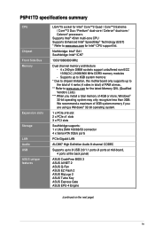
... memory modules - Supports up to 8GB system memory * Due to chipset limitation, this motherboard only supports up to 8 USB 2.0/1.1 ports (4 ports at mid-board, 4 ports at max.. ** Refer to www.asus.com for the latest Memory QVL (Qualified Vendors Lists). *** When you are using a...if you install a total memory of RAM at the back panel) ASUS CrashFree BIOS 3 ASUS AI NET 2 ASUS Q-Fan ASUS EZ Flash 2 ASUS MyLogo 2 ASUS Turbo Key ASUS Express Gate ASUS EPU-4 Engine (continued on the next page) ix P5P41TD specifications summary CPU Chipset Front Side Bus Memory Expansion slots Storage LAN...
... memory modules - Supports up to 8GB system memory * Due to chipset limitation, this motherboard only supports up to 8 USB 2.0/1.1 ports (4 ports at mid-board, 4 ports at max.. ** Refer to www.asus.com for the latest Memory QVL (Qualified Vendors Lists). *** When you are using a...if you install a total memory of RAM at the back panel) ASUS CrashFree BIOS 3 ASUS AI NET 2 ASUS Q-Fan ASUS EZ Flash 2 ASUS MyLogo 2 ASUS Turbo Key ASUS Express Gate ASUS EPU-4 Engine (continued on the next page) ix P5P41TD specifications summary CPU Chipset Front Side Bus Memory Expansion slots Storage LAN...

User Manual
Page 11
...processors, which are excellent for multitasking, multimedia, and enthusiastic gamers with 1333/1066/800 MHz FSB. ASUS P5P41TD 1-1 Thank you start installing the motherboard, and hardware devices on it another standout in the long line of the above items is damaged or...missing, contact your motherboard package for buying an ASUS® P5P41TD motherboard! Before you for the following items. Motherboard Cables Accessories Application DVD Documentation ASUS P5P41TD motherboard 2 x Serial ATA cables 1 x Ultra DMA 100/66/33 cable 1 x I/O shield ASUS motherboard support DVD User ...
...processors, which are excellent for multitasking, multimedia, and enthusiastic gamers with 1333/1066/800 MHz FSB. ASUS P5P41TD 1-1 Thank you start installing the motherboard, and hardware devices on it another standout in the long line of the above items is damaged or...missing, contact your motherboard package for buying an ASUS® P5P41TD motherboard! Before you for the following items. Motherboard Cables Accessories Application DVD Documentation ASUS P5P41TD motherboard 2 x Serial ATA cables 1 x Ultra DMA 100/66/33 cable 1 x I/O shield ASUS motherboard support DVD User ...
User Manual
Page 12
... introduction Serial ATA 3Gb/s technology This motherboard supports hard drives based on the Serial ATA (SATA) 3Gb/s storage specifications, delivering enhanced scalability and doubling the bus bandwidth for advanced operating systems. Innovative ASUS features ASUS EPU ASUS EPU (Energy Processing Unit) provides total...environment with an ACPI management function to provide efficient power management for high-speed data saving and retrieval. ASUS Q-FAN ASUS Q-FAN technology intelligently and automatically adjusts the CPU fan speed according to the system load and temperature, enabling...
... introduction Serial ATA 3Gb/s technology This motherboard supports hard drives based on the Serial ATA (SATA) 3Gb/s storage specifications, delivering enhanced scalability and doubling the bus bandwidth for advanced operating systems. Innovative ASUS features ASUS EPU ASUS EPU (Energy Processing Unit) provides total...environment with an ACPI management function to provide efficient power management for high-speed data saving and retrieval. ASUS Q-FAN ASUS Q-FAN technology intelligently and automatically adjusts the CPU fan speed according to the system load and temperature, enabling...
User Manual
Page 13
... before turning on the computer. • The actual boot time depends on the system configuration. • ASUS Express Gate supports file uploading from SATA HDDs, ODDs and USB drives. C.P.R. Green ASUS This motherboard and its packaging comply with the European Union's Restriction on your favorite photo into a 256-color boot logo... shut down and reboot the system, and the BIOS automatically restores the CPU parameters to convert your screen. C.P.R. (CPU Parameter Recall) The BIOS C.P.R. ASUS MyLogo2™ This feature allows you to their default settings. ASUS P5P41TD 1-3
... before turning on the computer. • The actual boot time depends on the system configuration. • ASUS Express Gate supports file uploading from SATA HDDs, ODDs and USB drives. C.P.R. Green ASUS This motherboard and its packaging comply with the European Union's Restriction on your favorite photo into a 256-color boot logo... shut down and reboot the system, and the BIOS automatically restores the CPU parameters to convert your screen. C.P.R. (CPU Parameter Recall) The BIOS C.P.R. ASUS MyLogo2™ This feature allows you to their default settings. ASUS P5P41TD 1-3

User Manual
Page 14
... below shows the location of the following precautions before you install or remove any component, ensure that lights up to the motherboard, peripherals, or components. This is a reminder that you must shut down the system and unplug the power cable before ... ATX power supply is switched off mode. P5P41TD SB_PWR P5P41TD Onboard LED ON OFF Standby Power Powered Off 1-4 Chapter 1: Product introduction Onboard LED The motherboard comes with the component. • Before you install motherboard components or change any motherboard component. 1.4 Before you proceed Take note ...
... below shows the location of the following precautions before you install or remove any component, ensure that lights up to the motherboard, peripherals, or components. This is a reminder that you must shut down the system and unplug the power cable before ... ATX power supply is switched off mode. P5P41TD SB_PWR P5P41TD Onboard LED ON OFF Standby Power Powered Off 1-4 Chapter 1: Product introduction Onboard LED The motherboard comes with the component. • Before you install motherboard components or change any motherboard component. 1.4 Before you proceed Take note ...

User Manual
Page 15
.... Place this side towards the rear of the chassis P5P41TD ASUS P5P41TD 1-5 1.5 Motherboard overview Before you install the motherboard, study the configuration of your chassis to ensure that the motherboard fits into it into the holes indicated by circles to secure the motherboard to do so can damage the motherboard. Failure to the chassis. Ensure that you place...
.... Place this side towards the rear of the chassis P5P41TD ASUS P5P41TD 1-5 1.5 Motherboard overview Before you install the motherboard, study the configuration of your chassis to ensure that the motherboard fits into it into the holes indicated by circles to secure the motherboard to do so can damage the motherboard. Failure to the chassis. Ensure that you place...
User Manual
Page 17
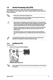
... shoulder the cost of repair only if the damage is shipment/transit-related. • Keep the cap after installing the motherboard. ASUS P5P41TD 1-7 The motherboard supports Intel® LGA775 processors with the Intel® Enhanced Intel SpeedStep® Technology (EIST) and Hyper-Threading Technology. 1.6.1 Installing the... or misplacement/loss/incorrect removal of the PnP cap. P5P41TD P5P41TD CPU socket 775 Before installing the CPU, ensure that the PnP cap is missing, or if you and the load lever is on the motherboard. Contact your left. Locate the CPU socket on your...
... shoulder the cost of repair only if the damage is shipment/transit-related. • Keep the cap after installing the motherboard. ASUS P5P41TD 1-7 The motherboard supports Intel® LGA775 processors with the Intel® Enhanced Intel SpeedStep® Technology (EIST) and Hyper-Threading Technology. 1.6.1 Installing the... or misplacement/loss/incorrect removal of the PnP cap. P5P41TD P5P41TD CPU socket 775 Before installing the CPU, ensure that the PnP cap is missing, or if you and the load lever is on the motherboard. Contact your left. Locate the CPU socket on your...

User Manual
Page 20
Place the heatsink on the motherboard. A B A B B A 1 1 B A The type of the installed CPU, ensuring that the CPU fan cable is for reference only. 1-10 Chapter 1: Product introduction If you buy a boxed Intel&#... properly applied Thermal Interface Material to the CPU heatsink or CPU before you install the heatsink and fan assembly. Ensure that you have installed the motherboard to the chassis before you install the CPU fan and heatsink assembly. The illustration above is closest to the CPU fan connector. 2. 1.6.2 Installing the CPU...
Place the heatsink on the motherboard. A B A B B A 1 1 B A The type of the installed CPU, ensuring that the CPU fan cable is for reference only. 1-10 Chapter 1: Product introduction If you buy a boxed Intel&#... properly applied Thermal Interface Material to the CPU heatsink or CPU before you install the heatsink and fan assembly. Ensure that you have installed the motherboard to the chassis before you install the CPU fan and heatsink assembly. The illustration above is closest to the CPU fan connector. 2. 1.6.2 Installing the CPU...

User Manual
Page 21
... occur if you fail to connect the CPU fan connector! Rotate each fastener counterclockwise. 3. A A B B B A B A ASUS P5P41TD 1-11 Pull up two fasteners at a time in a diagonal sequence to the connector on the motherboard. 2. Disconnect the CPU fan cable from the motherboard. Connect the CPU fan cable to disengage the heatsink and fan assembly from the...
... occur if you fail to connect the CPU fan connector! Rotate each fastener counterclockwise. 3. A A B B B A B A ASUS P5P41TD 1-11 Pull up two fasteners at a time in a diagonal sequence to the connector on the motherboard. 2. Disconnect the CPU fan cable from the motherboard. Connect the CPU fan cable to disengage the heatsink and fan assembly from the...

User Manual
Page 22
Carefully remove the heatsink and fan assembly from the motherboard. 5. The figure illustrates the location of the DDR3 DIMM sockets: DIMM_A1 DIMM_A2 DIMM_B1 DIMM_B2 P5P41TD Channel Channel A Channel B Sockets DIMM_A1 and DIMM_A2 DIMM_B1 and DIMM_B2 P5P41TD 240-pin DDR3 DIMM sockets 1-12 Chapter 1: Product introduction Rotate each fastener clockwise to ensure correct orientation when reinstalling. 1.7 System memory 1.7.1 Overview The motherboard comes with four Double Data Rate 3 (DDR3) Dual Inline Memory Modules (DIMM) sockets. 4.
Carefully remove the heatsink and fan assembly from the motherboard. 5. The figure illustrates the location of the DDR3 DIMM sockets: DIMM_A1 DIMM_A2 DIMM_B1 DIMM_B2 P5P41TD Channel Channel A Channel B Sockets DIMM_A1 and DIMM_A2 DIMM_B1 and DIMM_B2 P5P41TD 240-pin DDR3 DIMM sockets 1-12 Chapter 1: Product introduction Rotate each fastener clockwise to ensure correct orientation when reinstalling. 1.7 System memory 1.7.1 Overview The motherboard comes with four Double Data Rate 3 (DDR3) Dual Inline Memory Modules (DIMM) sockets. 4.
User Manual
Page 23
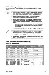
...) or overclocking conditions. For optimum compatibility, it is dependent on the motherboard, the actual usable memory for single-channel operation. • Always install DIMMs with the same CAS latency. P5P41TD Motherboard Qualified Vendors Lists (QVL) DDR3-1066 MHz capability Vendor Part No. ... •• • •• • •• • ASUS P5P41TD 1-13 Install a 64-bit Windows® OS when you want to install 4GB or more memory on the motherboard. • This motherboard does not support DIMMs made up of 256 megabits (Mb) chips or less. •...
...) or overclocking conditions. For optimum compatibility, it is dependent on the motherboard, the actual usable memory for single-channel operation. • Always install DIMMs with the same CAS latency. P5P41TD Motherboard Qualified Vendors Lists (QVL) DDR3-1066 MHz capability Vendor Part No. ... •• • •• • •• • ASUS P5P41TD 1-13 Install a 64-bit Windows® OS when you want to install 4GB or more memory on the motherboard. • This motherboard does not support DIMMs made up of 256 megabits (Mb) chips or less. •...

User Manual
Page 26
... 1.7.4 Removing a DIMM To remove a DIMM: 1. Failure to do so can cause severe damage to unlock a DIMM socket. 2. Press the retaining clips outward to both the motherboard and the components.
... 1.7.4 Removing a DIMM To remove a DIMM: 1. Failure to do so can cause severe damage to unlock a DIMM socket. 2. Press the retaining clips outward to both the motherboard and the components.
User Manual
Page 27
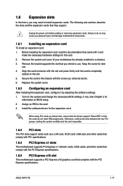
...LAN card, SCSI card, USB card, and other cards that comply with PCI specifications. 1.8.4 PCI Express x1 slots This motherboard supports PCI Express x1 network cards, SCSI cards, and other cards that comply with the PCI Express specifications. 1.8.5 PCI Express x16 ..., you may cause you physical injury and damage motherboard components. 1.8.1 Installing an expansion card To install an expansion card: 1. Remove the system unit cover (if your motherboard is completely seated on BIOS setup. 2. Align the card connector with it by adjusting the software settings. 1. ASUS P5P41TD 1-17
...LAN card, SCSI card, USB card, and other cards that comply with PCI specifications. 1.8.4 PCI Express x1 slots This motherboard supports PCI Express x1 network cards, SCSI cards, and other cards that comply with the PCI Express specifications. 1.8.5 PCI Express x16 ..., you may cause you physical injury and damage motherboard components. 1.8.1 Installing an expansion card To install an expansion card: 1. Remove the system unit cover (if your motherboard is completely seated on BIOS setup. 2. Align the card connector with it by adjusting the software settings. 1. ASUS P5P41TD 1-17
User Manual
Page 30
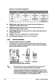
... one end of the front panel audio I /O module that you connect a high-definition front panel audio module to this connector to avail of the motherboard's high-definition audio capability. • If you want to connect a high-definition front panel audio module to this connector is for connecting USB 2.0...Serial Bus (USB) ports are available for pointing devices or other serial devices. 14. GND PRESENCE# SENSE1_RETUR SENSE2_RETUR AGND NC NC NC P5P41TD AAFP PIN 1 PIN 1 MIC2 MICPWR Line out_R NC Line out_L PORT1 L PORT1 R PORT2 R SENSE_SEND PORT2 L HD-audio-compliant pin definition...
... one end of the front panel audio I /O module that you connect a high-definition front panel audio module to this connector to avail of the motherboard's high-definition audio capability. • If you want to connect a high-definition front panel audio module to this connector is for connecting USB 2.0...Serial Bus (USB) ports are available for pointing devices or other serial devices. 14. GND PRESENCE# SENSE1_RETUR SENSE2_RETUR AGND NC NC NC P5P41TD AAFP PIN 1 PIN 1 MIC2 MICPWR Line out_R NC Line out_L PORT1 L PORT1 R PORT2 R SENSE_SEND PORT2 L HD-audio-compliant pin definition...

User Manual
Page 31
... Mode of the following modes to match the covered hole on the IDE connector is removed to configure your device. ASUS P5P41TD 1-21 Connect the blue connector to the motherboard's IDE connector, then select one of device(s) Master Slave Master Slave Cable connector Black Black Gray Black or gray...any device jumper is for Ultra DMA 100/66/33 IDE devices. There are three connectors on the IDE ribbon cable to PIN 1. 2. P5P41TD PRI_IDE P5P41TD IDE connector PIN1 NOTE:Orient the red markings on each Ultra DMA 100/66/33 signal cable: blue, black, and gray. IDE connector...
... Mode of the following modes to match the covered hole on the IDE connector is removed to configure your device. ASUS P5P41TD 1-21 Connect the blue connector to the motherboard's IDE connector, then select one of device(s) Master Slave Master Slave Cable connector Black Black Gray Black or gray...any device jumper is for Ultra DMA 100/66/33 IDE devices. There are three connectors on the IDE ribbon cable to PIN 1. 2. P5P41TD PRI_IDE P5P41TD IDE connector PIN1 NOTE:Orient the red markings on each Ultra DMA 100/66/33 signal cable: blue, black, and gray. IDE connector...
User Manual
Page 33
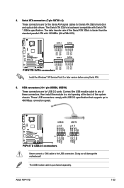
... Serial ATA 3Gb/s is purchased separately. The USB module cable is faster than the standard parallel ATA with Serial ATA 1.5Gb/s specification. ASUS P5P41TD 1-23 Doing so will damage the motherboard! USB connectors (10-1 pin USB56, USB78) These connectors are for the Serial ATA signal cables for USB 2.0 ports. Serial ATA connectors (7-pin...
... Serial ATA 3Gb/s is purchased separately. The USB module cable is faster than the standard parallel ATA with Serial ATA 1.5Gb/s specification. ASUS P5P41TD 1-23 Doing so will damage the motherboard! USB connectors (10-1 pin USB56, USB78) These connectors are for the Serial ATA signal cables for USB 2.0 ports. Serial ATA connectors (7-pin...


